In last week’s post I told you about Rotary Snow Plows and my intention to make a model of UP 900081, the largest and most powerful rotary in the US. You can find the post here. In this week’s post I’ll go into a bit more detail about what I’m going to do.
UP 900081, as pictured below, is currently on display at the Museum of Transportation, St. Louis, Missouri, which is really useful as there are now lots of pictures available as reference material.
For my model the main body will be 3D printed in Shapeways FUD or FXD materials simply because to date this produces the best results. And I’ll be setting the print orientation so the model is printed the right way up. (To see why this is important see my post about 3D print orientation here).
A lot of the surface area on the sides is flat so to help keep it smooth I’ll be making all the grab irons and ladders from etched brass. This has two advantages; firstly, anything sticking out of the side of the print needs support material underneath it in the print process and this can leave a shadow on the surface, and secondly, the etched parts look better. This has worked well on my other locomotives such as my Alco C855 as shown below.
This time I’m also going to include the mesh grills as an etched brass part. The mesh frame will be 3D printed as part of the shell and a fine mesh will fit in behind. This will allow you to see inside slightly as with the original.
Other details will also be made from etched brass such as the side window wipers and the unusual rotating windows on the front. These special windows, shown in the photo below, rotated continuously preventing snow from settling and obstructing the windows. (Photo of UP 900082 taken at Cheyenne 14th June 2000 by Don Strack),
In this close up on Don’s photo you can clearly see the rotating windows. My 3D printed shell will have a lip behind the window to receive a piece of clear plastic to form the glass and the etched rotating window will sit on top.
The big twelve-foot fan at the front will also be 3D printed but as a separate part as I want this to be able to rotate. In fact in my model it will be powered. I will have more on how that will be done next week.
Above the fan is the directional chute which will also be a separate part so it can be flipped from left to right.
The trucks on the rotary are not standard either, well, the second one is as it’s recycled truck from a C&O steam tender, but I think the front truck was constructed from parts, making it unique to the rotary.
These will also be 3D printed but they will only be side frames as they will fit onto the chassis which will be a bought in. Why not 3D print one? Because I want good reliable power pickup and a motor to drive the fan. The easiest way to do that is to use a powered chassis that works well. I will also make a 3D printed chassis and trucks for anybody wants an unpowered version.
Behind the front truck is a snow plow which can be lowered to prevent snow building up under the fuel tank, but this is N Scale so that will be a 3D printed part of the shell. It will also depend on how the new chassis fits in at that point.
In next week’s post I’ll share with you which chassis I’ll be using and how it will be connected up to the fan (if it arrives in the post in time). For now I’ll leave you with a quick render of how my 3D model looks so far.
Although I have may projects currently working through the system there is always room for one more and this week, given how cold it is and in some parts snowy, it seems the ideal time to start sharing with you my plans for an N Scale Union Pacific rotary snow plow.
This project is at the request of a fellow modeller but it’s one I have been thinking about for a while for myself, I think the rotarys are just fantastic!
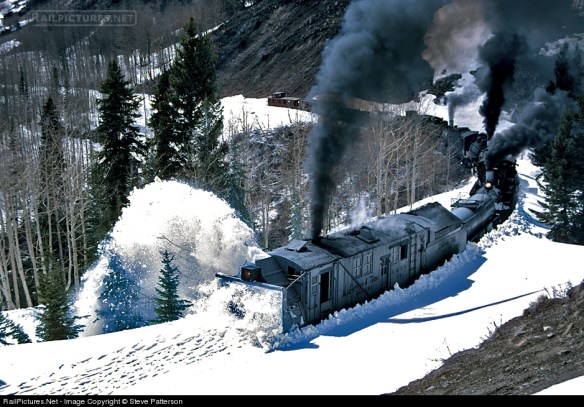
So what are rotary snow plows? In short they’re the last line of defense against heavy snow fall; when the snow’s falling and regular plows and shovels simply can’t do it the rotarys are called out to cut their way through. And they do literally cut their way through. In the image below, taken by Steve Patterson and displayed on Railpictures you can see ex-DRGW steam rotary ‘OY’ being pushed by three steam locomotives.
The photo caption says: ‘In an attempt to open its line from winter snows, Cumbres & Toltec Scenic operated a triple-header rotary snow plow train on May 3, 1997. Three mikados are shoving Rotary OY as they near the deepest snow encountered on Windy Point, Colo., just short of the summit at Cumbres Pass which wouldn’t be achieved until the next day. The footprints in the snow ahead of the rotary are from pursuing photographers.’
Regular snow plows work by forcing the show aside and for the majority of areas this is just fine. In winter months you can often see plows fitted to regular locomotives as with UP 9564 in the photo below. (Picture from Home Town by Handlebar).
But when it gets a bit deeper the plow has nowhere to push the snow so it needs to be lifted above. This can be done with a larger dedicated plow which is pushed by locomotives as shown below. (Photo by Kevin Burkholder and displayed on Railpictures).
The large ‘scoop’ at the front pushes the snow up and out to the sides, the ‘wings’ (behind the plow with VB 103 marked on the side) can be adjusted to push the snow even further, and retracted to pass objects close to rails. Plows like this come in all sorts of shapes and sizes as railroads tended to build their own out of freight cars, caboose and tenders. The important thing is they needed to be heavy as hitting a snow bank at speed creates quite an impact as you can see in the video below. (courtesy of James Adeney from You Tube).
But when the snow gets really deep you simply can’t push through so out come the rotarys. At the front, as shown below, is a large rotating cutting face or fan. This breaks the snow down and forces it out a chute on the top. The chute can be angled to the left or right and throws the snow far away from the railroad. (Photo by Alix Gillman and displayed on Railpictures).
The rotarys move much slower than the plows as they cut through but the only limitation is the amount of power to the fan and how much tractive effort is pushing it into the snow. Typically rotarys are not self-propelled, all the power they generate is used to drive the fan, so they will often be seen with several power units pushing from behind. The early rotarys were all steam-powered which gave the added advantage of heat. Not only would the boiler provide steam to drive the fan but also to melt the ice which built up around the front. The steam rotary below, pictured by Brian Snelson on Flicker, was built in 1898 and was used right up until 1968. It’s typical of an early design with a traditional steam engine tender behind for fuel and water.
As these machines were not in constant use, often only used every five to ten years, they were kept in running order but had little need for updating. However as steam started to become obsolete on the class one railroads they started converting them to diesel and electric power. A good example of this is the Southern Pacific with their route over Donner Pass. They converted the actual rotary to electric power. It was also coupled to a spare EMD F7 B unit which had its traction motors removed and all four installed into the rotary to power the fan. The B unit produced the power for the fan motors. A steam generator was also fitted to keep the front clear of ice and supply warmth to the crew. Controls were added so the crew could control the pushing locomotives from up front. In the image below you can see two rotarys and their F7B units, one at each end of some modern locomotives, as they wait for a passenger train to pass. Up in the high mountains of Donner Pass they often worked like this so they could clear snow in both directions continuously. (Photo by Jake Miille Photography)
This photo is accompanied by a short video of the rotarys working on Donner Pass on February 25th, 2017.
Although the Union Pacific Railroad had many steam rotarys over the years purchased from specialist manufacturers, in the late 1950’s and 1960’s they also built some of their own and it’s one of these which I’m creating a model of. As they started from scratch on their new rotarys it was easy to build them just how they wanted.
UP 900080 was constructed in 1958 at the UP Omaha shops. It was built on the frame and rear truck from a retired ex C&O steam tender. It has a 1750hp diesel engine to drive the 12′ rotary fan, weighs 347,240 pounds, is 50′-9″ long and 16′-8″ high. (Photo by Steve Patterson and displayed on Railpictures).
UP 900081 was constructed in 1966 at the UP Omaha shops again on the frame and rear truck from a retired ex C&O steam tender. This time UP put in a 3000 hp diesel engine making this rotary the most powerful and weighing 367,400 pounds also the heaviest rotary in the United States. It is 52′-2″ long, 17′ high and the rotary fan is 12′ in diameter. (Photo by Joe Bracey and displayed on Railpictures).
UP 900082 was constructed in 1971 also at the UP Omaha shops. It has a 2500 hp diesel engine, weighs 284,500 pounds, is 55′-3″ length, 17′ high and has a rotary fan 12′ in diameter. (Photo by Mike Danneman and displayed on Railpictures).
Out of the three 900080 and 900082 are still in service but sadly 900081 was damaged in 1994. UP retired the rotary but donated it to the Museum of Transportation, St. Louis, Missouri later that year where it’s now on display.
As 900081 was the most powerful, 900082 currently holds that honor, it’s this one which I’m modeling, although it’s very similar to 900082 so it could be used for either. The plan is to have a free rolling chassis but still have a motor inside to power the fan. To do this I will most likely use a commercial chassis from a diesel locomotive and remove the drive gear from the truck towers. Then I’ll connect the drive shaft to the fan. Sounds very similar to what SP did with theirs!
Next week I’ll share with you some of the design drawings and go over some of the finer details I intend for the model. To round-up this week’s post I’ll leave you with two videos of the White Pass & Yukon Railway’s steam rotary plow doing what it does best. (Both courtesy of Murray Lundberg from You Tube).
This week I’d hoped to show you the 3D printed replacement Minitrix Crosshead from last week’s post however due to the heavier than normal snows last night I’ve had no delivery today. So this week I’ll share with you something else which should also be arriving soon.
The venerable Con-Cor Alco PA has been around since 1967 and has been improved over the years but the original design, made by Kato under the name Sekisui, can still be found going strong on many layouts; mine included. One of the things which made this design different from the later is how the chassis sections are fixed together. The original design had a solid metal section on the top and two metal sections below, one making contact with each rail through the trucks. Between the top and bottom sections is a strip of plastic for electronic isolation. It’s all clamped together with screws, metal ones on one side to conduct power from the lower section to the top, and plastic screws on the other to isolate that section. This works well, but the plastic screws, if removed a lot, can easily be rounded off. Plus if you drop one into the bottomless depths of an exhibition hall they are very hard to replace.
But thankfully I have a solution.
These have been designed to be 3D printed in Shapeways’ Frosted Ultra Detail material to give the required accuracy for the thread and hardness for the actual screw.
Hopefully these will be delivered soon, along with the other parts, and I will be able to share some photos with you next week. Plus it will be nice to have my Alco PA back on the tracks.
Trix produced a variety of locomotives including a range in N scale, dating back to the 1960s, under the name Minitrix. Many of these shared common parts and it’s one of these for which I’m creating a replacement; a Minitrix valve gear cross head.
This particular cross head will be for the A4 steam locomotive model shown below.
The cross head is the gray slider which connects the piston and the main connecting rod. This plastic part slides up and down the metal runner as the piston goes in and out, keeping it level and it also connects the valve gear linkage.
As with a lot of the early plastic parts these can become very brittle and start to break up. Almost all the other parts of the locomotive’s motion are made from metal, the only exception is the crank pin which drives the eccentric rod. This is also made from plastic and I’ve previously made this as a replacement 3D printed part; you can read more about that here. You can identify the crank pin in the first image as it’s gray and not silver, just like the cross head.
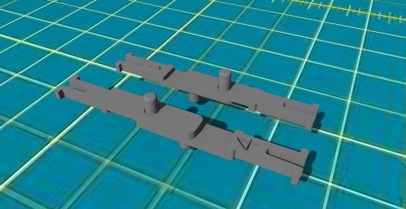
The original cross head is a very small part and very difficult to photograph up close so the image below is my 3D model of the part, without any modifications.
The cross head is symmetrical so it can be used on each side of the locomotive. The box section on top has slots in the sides to allow the slider to pass through. Below the box is a pair of rings, the first connects the cross head to the connecting rod and piston. As these are joined with a pin the connecting rod is able to rotate as the cross head slides back and forth. The second ring connects to the valve gear linkage, again with a pin allowing it to rotate.
The weak spot on these parts is where the rings connect to the box. If the valve gear becomes jammed and the wheels keep turning a twisting force is applied at this point. If the plastic has started to break up it will simply snap.
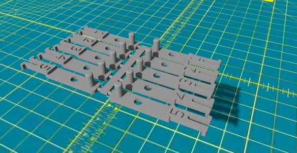
In the image below you can see three cross heads with the original on the left. The middle one has had the weak area under the box strengthened by adding a larger amount of plastic. The right hand side one has also had the area between the loops strengthened in the same way and it’s this version which I’m test printing.
This cross head fits most of the British outline steam locomotives including the Gresley A3, A4, Standard 9F, Ivatt 2-6-2 Tank and the Ivatt 2-6-0. Only the Britannia 7P had a different valve gear with a simplified cross head consisting of a folded metal plate. Minitrix also made two steam locomotive for the American market, a 4-6-2 K4 and a 2-10-0 Decapod. As the 2-10-0 shared the same chassis as the 9F this also has the same cross head. The K4 shared the simpler Britannia 7P chassis.
The part has now been printed by Shapeways and I’m expecting it later this week, and once tested will be made available to buy. It’s often these small, seemingly insignificant parts that aren’t glamorous or even particularly interesting, that 3D printing really comes into its own. The ability to modify, improve and manufacture replacement parts at a fraction of the cost of replacing the locomotive means we can keep the majority of our stock rolling, and it’s why I continue to produce these parts.
In last week’s post I shared with you my designs for some 3D printed OO Gauge fixed link couplings specifically for coaches; you can find the post here. This week I’ll be showing you the actual couplings and some images of them in use.
The initial test prints were done in Shapeways White Strong & Flexible material. I chose this because it’s the cheapest material they do. I’ve also used the Strong & Flexible material, instead of my normally prefered Frosted Detail plastics, as these couplings don’t need any fine detail. As they are hidden they simply need to function. In the image below you can see a set of the white couplings in a pair Bachmann Mark 1 coaches. This particular set turned out to be too short as the corridor connections meet before the pegs could locate into their holes.
But the good news is I test printed several different sizes in order to see what worked and I was able to come up with a set of 5 which covered all bases.
Below is a set of 40 Type 2 or length 2 couplings. These are the second shortest type. This time I 3D printed them in the Black Strong & Flexible material which will also be used for the final couplings.
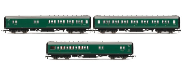
These couplings were originally developed for use on the beautiful new model of Bournemouth West. So a good set of coaches to test the new couplings on is Hornby’s British Railways Somerset & Dorset Maunsell coaches, as they would have been common in this station.
In this stock photo below you can see the big gap between the coaches using the standard OO couplings.
However with my coupling fitted, the corridor connections are millimeters apart, as you can see in the images below. This gives the impression of a joined connection.
And as these coaches are fitted with the NEM cam system, this causes the NEM socket to swing and move out on corners; the gap increases as the coaches travel around corners. This prevents the corridor connections and buffers from locking up and derailing the coaches.
The overall effect is very good. Also they won’t come uncoupled but can simply be lifted off the layout when done.
These couplings also work well for the Bachmann Mk’1 coaches.
This older set wasn’t fitted with the cam system but my couplings still worked well around the corners, as the NEM socket swivels.
The Hornby Pullman coaches have their NEM couplings set much further back than the others I’ve tested so far and required a longer coupling. The ones used below are still a bit too long but this has been corrected in my computer model.
Here are some videos of the test couplings in use with a push-pull service reversing around the corner and heading into Bournemouth West Station.
And again with a section of the Bournemouth Belle coming around the corner and heading into Bournemouth West Station.
And finally with the Pines Express; some of these coaches have Kadee couplings but mine have been used on the rest.
Just of interest, the layout Bournemouth West will be making its debut appearance at the Swindon Railway Festival, held at the Swindon Steam Museum on the 9th and 10th September 2017.
Next week I plan to share the couplings with you in their finished condition and also let you know where you can get them.
At long last my freight couplings for British OO rolling stock with NEM sockets are now available, so it’s time to share with you my designs for coach couplings. You can find the freight couplings here.
Early British coaches had similar coupling to the freight 3 link. They each had a hook and a chain, but because passenger stock needs to be smooth, the chains had a screw section in the middle. This worked by having the locomotive push two coaches together so the buffers compressed, then the chain was hooked over the hook and the screw tightened up. When the locomotive releases the pressure the buffers can never fully un-spring. This means there’s never any slack which would cause the train to snatch and jerk, as that’s not ideal when you’re sitting down to lunch! Below is an example of a locomotive coupled to a coach with a screw link coupling.
Later coach stock adopted the knuckle coupler, very similar to the standard system used in the US. The difference is the knuckle can rotate around the hook so both systems could be used. The knuckle coupler would hang down allowing normal access to the hook. When needed, the knuckle coupler was lifted and held in place by a pin. In the picture below you can see this arrangement on a BR Mk 1 coach. (Picture by Chris McKenna from Wikipedia)
The pin also held the knuckle down when not in use to prevent it from swinging. This has also been implemented on locomotives. You can see it on the front of the BR Class 91 locomotive below. (Picture by Chris McKenna from Wikipedia).
Modeling this can done and, with newer models now having the NEM sockets, different couplings can easily be exchanged. A plug-in Kadee knuckle coupler is available for the NEM socket and it’s a good way to connect coaches. However as with the freight stock, if you have rakes of coaches which you want to stay permanently coupled, adding Kadee couplers comes with the risk of separation plus the expense of adding one to each end of every coach. Bachmann make a coupling designed to be a fixed link between coaches which looks like vacuum pipes hanging down. Again this is a good idea but what if you run trains at exhibitions or like to swap the trains on your layout? Picking up 5 to 10 coaches all linked together is a bit tricky.
So how is 3D printing a coupler better than this? Well, the nice thing about coach stock is they normally have a corridor connection so travelers can move from coach to coach; this hides the coupling. Therefore the coupling doesn’t have to represent anything, it simply needs to work.
My coupling is just that, simple.
Each has a peg and hole at one end and the NEM fitting at the other. The two couplers simply overlap. The height of the peg ensures they won’t come uncoupled but when you want to remove the coach from the layout you simply pick it up.
As with the freight rolling stock different manufactures have placed their NEM sockets in different locations causing the gap between coaches to vary. This gap will also need to be specific to your layout depending on the radius of your curves. So to solve this I have made a few options in length.
And unlike the freight couplings there are only a few; five different types in fact.
They can be used in pairs with the same number or mixed together to give any required length.
Next week I’ll share more with you regarding these couplings and some images of them in use.


 Here are some videos of the test couplings in use with a push-pull service reversing around the corner and heading into Bournemouth West Station.
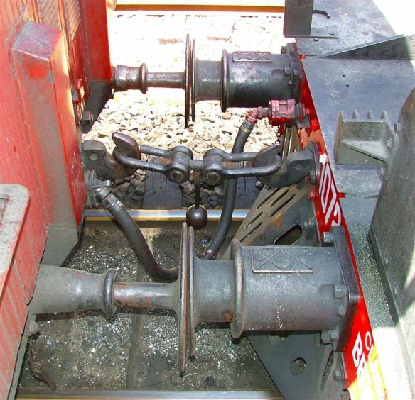

 Modeling this can done and, with newer models now having the NEM sockets, different couplings can easily be exchanged. A plug-in Kadee knuckle coupler is available for the NEM socket and it’s a good way to connect coaches. However as with the freight stock, if you have rakes of coaches which you want to stay permanently coupled, adding Kadee couplers comes with the risk of separation plus the expense of adding one to each end of every coach. Bachmann make a coupling designed to be a fixed link between coaches which looks like vacuum pipes hanging down. Again this is a good idea but what if you run trains at exhibitions or like to swap the trains on your layout? Picking up 5 to 10 coaches all linked together is a bit tricky.
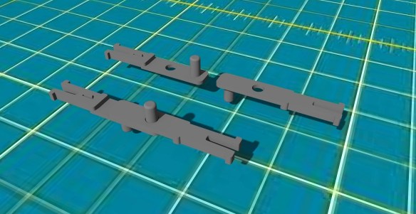
 They can be used in pairs with the same number or mixed together to give any required length.
You must be logged in to post a comment.