Since this blog was started back in November 2013 the hope was at some point to turn this love of 3D printing model railway parts into a full-time business. The blog has built a strong following, with everyone from those who just read, to those who have become regular customers and friends. The response and support has always been very much appreciated. And you’ve enabled this to go from a part-time enterprise that grew from the love of a hobby to a full-time professional model railway business.
The only downside is the lack of time available now the business is full-time! It has very quickly evolved from a parts replacement and development business to a model railway building business. The working week is now full of working on customer layouts on everything from layout design, track-laying, wiring, to problem-solving and upgrading for more reliable and enjoyable train time. This is great news, but the blog has suffered; it hasn’t had the level of attention it deserves for a while because time has been taken away from 3D drawing and printing.
So please bear with us as we manage the balance between the smaller projects that helped get this business off the ground and the full days working in various houses, garages, attics, basements and spare rooms! The 3D printing side of the business is just as important; layouts are only as good as the trains running on them and making sure those run effectively is what started this whole thing.
As promised in my last post I have an exciting announcement to make this week. James’ Train Parts has been my passion since November 2013 when I first wrote about drawing a 3D printed shell for an EMD DD35 for N Scale. And I’ve done lots more since then. As well as all the 3D printed parts and things I’ve posted about here, I’ve also been regularly repairing trains and fitting sound decoders, but what many may not know is I’ve also been building layouts for customers.
However, this is a lot to do when you also have a full-time job! I’ve had a huge amount of support from taking my small one man business to a group of individuals who are a part of the model railway community and an essential part of the work I’ve been doing over the last year. Which leads to my big announcement…
In just two weeks’ time we’re turning a part-time hobby business into a full-time enterprise and following our dreams of filling our working days with model trains and railways. With continuing support over the last few years we’ve steadily built a small business providing layout design, construction, electronics and scenery, as well as servicing and repairing existing layouts and trains. With ever-increasing demand from a growing customer base now is the time to take the opportunity most just get to dream of, so here we go!
This blog will continue under the new business name, the old James’ Train Parts address will still work, and you’ll start to see more posts about the layout construction and work we do.
Thank you for your support in helping me get to this stage, the blog has been successful in ways I could never have imagined, and I look forward to sharing my next step with you all.
This week I have a new product to share with you. As with most of my replacement parts, they’ve been designed and produced because a customer’s model has a broken part that’s no longer available from the manufacturers. And this week’s part is precisely for that reason.
Bachmann’s OO scale class 45 and 46 locomotives that were sold in the blue box and advertised as the new ‘Super Smooth Fly Wheel Gear Drive Motor’ came out in the mid-1990s and are normally very good runners, super smooth as it says on the box. These models have since been superseded by Bachmann so parts are no longer available.
Compared to other manufacturers’ models at the time that often had a single powered bogie at one end, this has a heavy centred motor that powers both bogies via swivelling drive shafts. However, as we’ve seen with several other models such as the Athearn DD35A from a few weeks ago, the plastic parts of these drive shafts can start to break with age. The primary cause of failure is due to the fact that they are press-fitted onto a metal shaft and the continuous outwards force eventually cracks the plastic.
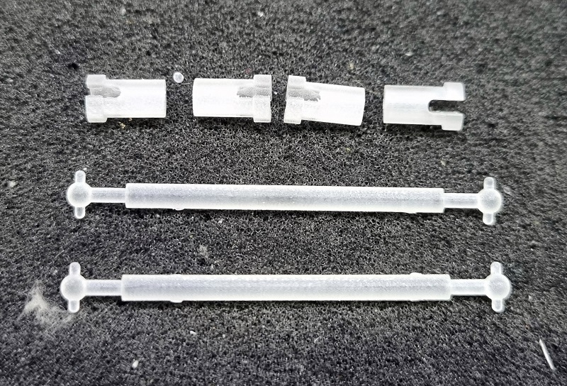
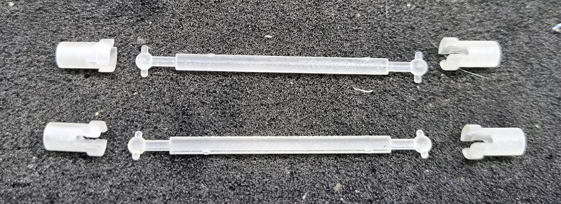
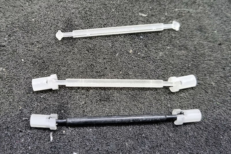
To repair these locomotives I’ve made a kit available containing two complete drive shaft assemblies.
The parts have been printed in Shapeways Smooth Fine Detail material for its hardness and accuracy.
There is a ball joint for each end of the drive shafts which connect to the motor or worm gear spindle.
I’ve designed them so they work with the existing parts, therefore you can change just the parts that are damaged or everything.
The bogie for this locomotive only has power to the center wheels via the plastic tower gears. The metal worm gear sits in brass bearings on top of the bogie tower.
It’s the ball joint that connects to this spindle that I find breaks in most cases with these locomotives, so I only replaced this part and used the original driveshaft to get this locomotive back on the layout.
If you have a Bachmann Class 45 to 46 with this issue, you can get the drive shaft kit here.
If you’re a regular reader of my blog you may have noticed several gaps in what I had intended to be weekly posts. However, there’s a good reason for this and I’ll be making an exciting announcement in roughly three weeks. Until then it’s back to the drawing board.
One of my customers has been having some issues with his layout since switching to DCC operation; they find that trains short and stop when crossing Peco Insulfrog crossings. In this post I’ll explain why this happens and show you how I fix it.
The Peco Insulfrog crossing comes in short and long versions and can be used in many ways. The term Insulfrog refers to the areas where rails cross each other, which is called a ‘frog’. An Insulfrog has a plastic separator to isolate the rails electrically. With an Insulfrog crossing, the two tracks are electrically separate from each other. So differently controlled trains can run on each line, as long as they don’t hit each other.
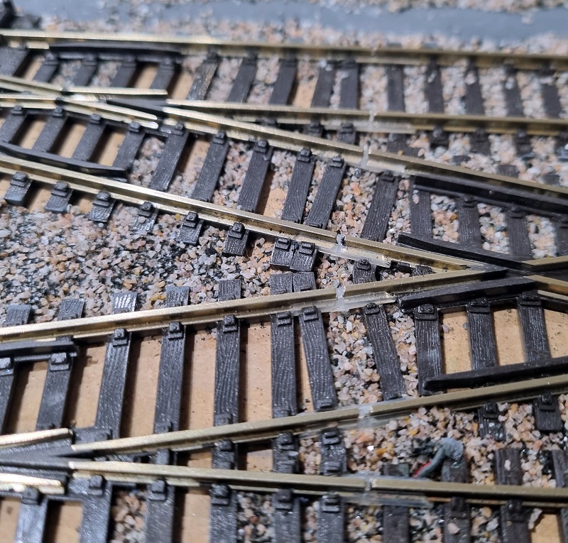
But the problem comes right at the centre of the frog where trains with wide wheels cross the plastic isolation. In the image below I’ve circled the area called the ‘frog’. The downside is here the larger the plastic frog, the bigger the dead spot is, or area without power, for the locomotives. So Peco has made it as short as possible to limit the dead spot. However, if a locomotive or regular item of rolling stock has wide metal wheels, that is, wider than the rail, the wheel will make contact with both incoming rails at the tips.
When using these on a traditional DC or Analogue layout there tends to be no issue with shorting at the frog because power is normally only given to the tracks a train is running on either by a power routing point or switch, so it’s more than likely the other track is switched off. However, with DCC all the track is powered and shorts at the frogs are very likely. This is why Electrofrogs, which means the frog is made of all metal, are ideal for DCC. But the polarity of the frog, positive or negative needs to be switched depending on the direction the train needs to travel.
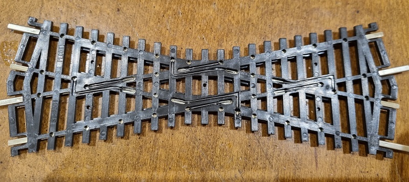
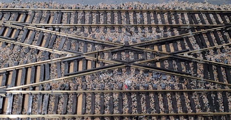
My customer has several of these crossings, the one below is at a major junction between four double slips. To solve the issue of trains shorting on this crossing I’m going to upgrade it to work like an Electrofrog crossing, just without the metal frogs.
Fortunately my customer had already installed insulating fishplates at the ends of the frogs. This is always needed with Electrofrog points, crossings and slips but not for DC/Analogue. If these were not already there I would need to cut the track using a slitting disc in a Dremel-style tool to create the gap.
To completely isolate the frog section, I need to cut the rails on the inside of the frog as well. The cuts want to be roughy in the middle of the rails section; this is because Peco has placed a wire under the plastic frog to bridge it. You can see the bridge wires below. The cuts need to be between these wires.
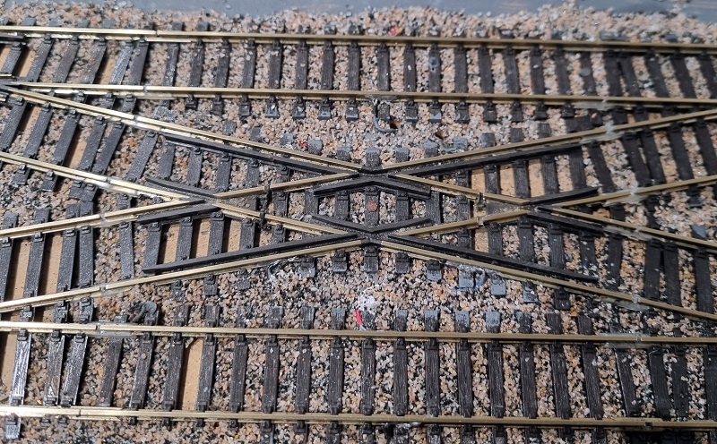
Using a slitting disc in a Dremel tool I’ve cut the rail in four places, above the gap in the sleepers to help keep the integrity of the rail support.
It’s important to make sure you cut deep enough to go all the way through the metal rail.
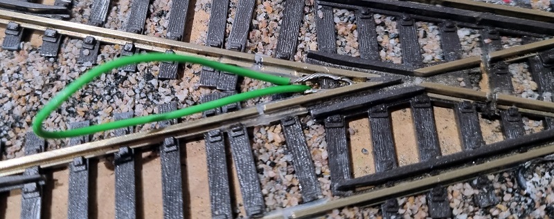
The frog area should now be completely isolated from everything, and currently, the two frog rails are separate from each other. To get power to them, I drill a hole just outside the frog and feed a wire through, I always use green, because most frogs are green! I strip more than normal off the end of the wire and twist the strands.
Then I loop the end, not a full 180° but to the same angle as the frog.
The stripped wire can then be pushed into the web of the rail which is below the railhead and out of the way of any passing trains. The wire needs to be in contact with both rails.
The wire can now be soldered to both rails which creates a basic Electrofrog. The excess wire is pulled back through the base board.
This is repeated on the other side of the crossing.
Although the frogs are now connected to a wire they will need to switch to the right power feed depending on which way a train is going. If it’s going from top left to bottom right the left frog will need to be connected to the bottom rail, but if travelling from the bottom left to top right it will be the top rail. This could be done with a manual switch but to make things easier I like to use Autofrogs. These are electronic relays or automatic frog polarity switches which detect if the frog is at the wrong supply and switch it before the DCC command station realizes there’s anything wrong.
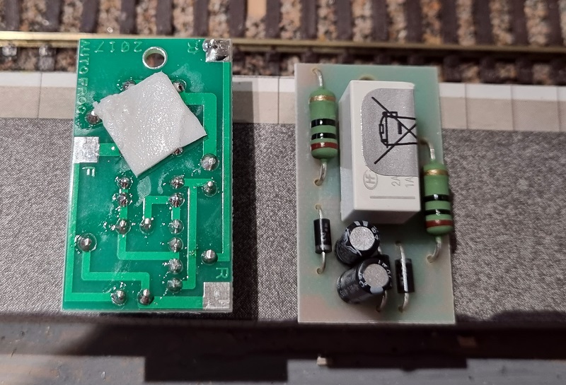
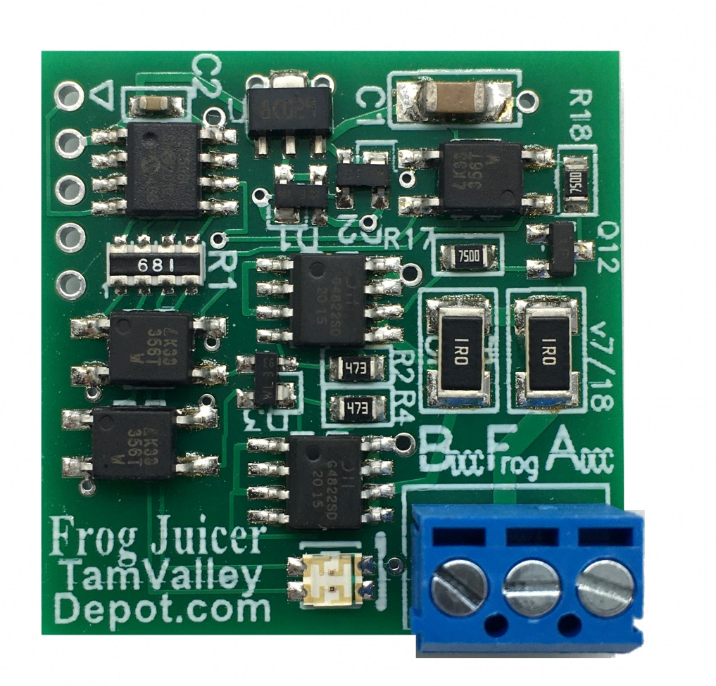
On the reverse of each one are three solder pads. The one marked F, on the left, is for the frog wire. The other two marked R, are for rail connections. It doesn’t matter which way round the DCC is connected to these pads as the Autofrog will always pick the right one itself.
I first add some solder (often called ‘tinning’) to all the pads.
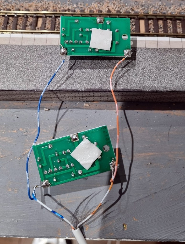
Then I connect the power cables This particular layout uses four core cables to connect power and track power to its point motors so I used the same wires.
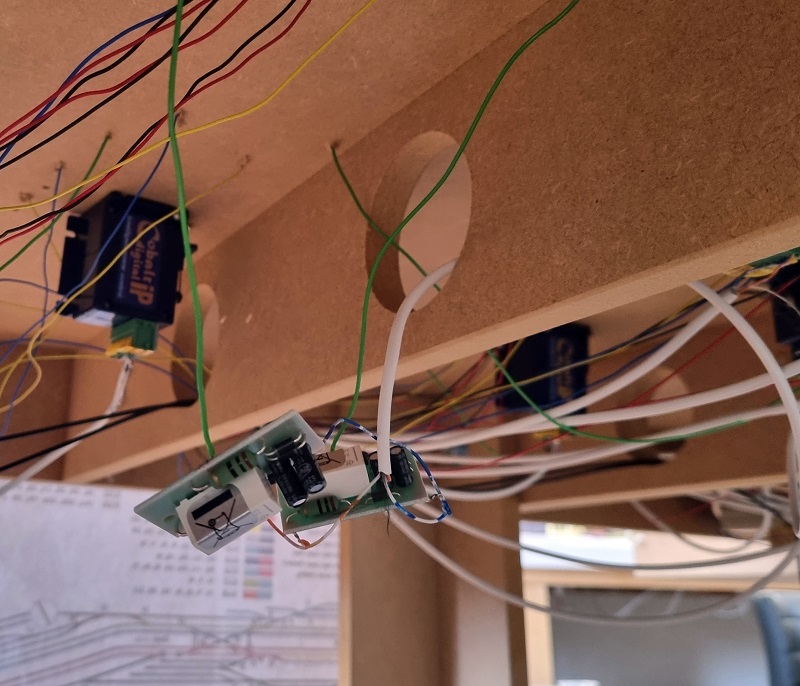
The frog wires are then connected to the Autofrogs under the layout and the four core cable is connected back to the main DCC bus.
At this stage, I run trains through the crossing to check it all works as anticipated. As a train crosses in a different direction to last time you should hear a faint click from the Autofrog as it changes the polarity, the train should carry on without even noticing. Which it did.
The last thing to do is secure the Autofrogs, and they have a single hole which can be screwed to the base board.
Doing this eliminates the shorting issues and trains now run without shorts and stalls.
The Gaugemaster Autofrogs work well but they’re not the only product that works like this. Tam Valley makes a product called a Frog Juicer which is all electronic, unlike the Autofrog which has a mechanical relay.
I’ve used both many times and both are very good. Although the Frog Juicer is slightly more expensive it does come with screw connections so soldering is not required.
When it comes to upgrading to DCC there are other ways to try and overcome the problem of shorting, but as a permanent solution with Insulfrogs this fix can be done without lifting the track or replacing it, and enables trains to run smoothly so you can get on with enjoying your layout.
As well as replacement gear sets I also do a lot of replacement driveshafts and this week I have a 3D print project to share with you that repairs an old Athearn HO DD35A.
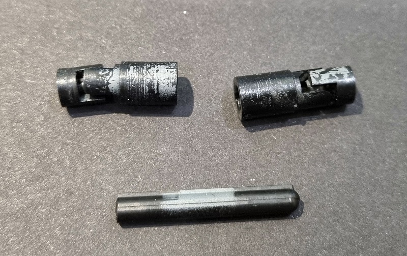
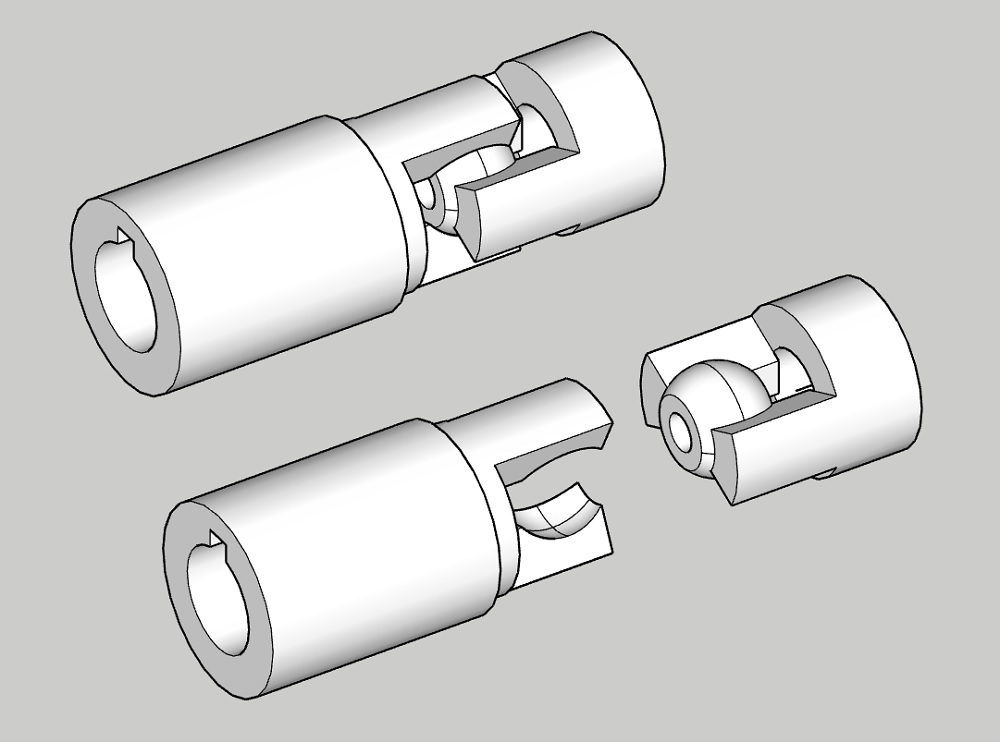
These big locomotives have two motors, just like the real thing. Each motor has a drive shaft that connects to the top of the truck and, through a set of gears, drives the wheels. But as the truck swivels the drive shaft has to adjust in direction and length. This is done by the use of universal joints and a sliding driveshaft. The ends of the universal joints are press-fitted onto the metal shafts of the motor and truck. And it’s at this point where they fail; the plastic cracks with age and no longer grips the metal shaft, preventing it from turning. Below is an original complete drive shaft with two universal joints and a sliding centre shaft.
You can just make out the cracks in the plastic in the image below on the right. Oddly the metal shaft on the motor (the universal on the right) is larger than the truck as you can see by the different hole sizes.
The sliding shaft has a keyway along its length; you can see it below on the top of the shaft.
The end of the universal this connects with has a slot for the keyway to fit into. This means the drive shaft will always turn the universal but can slide in and out.
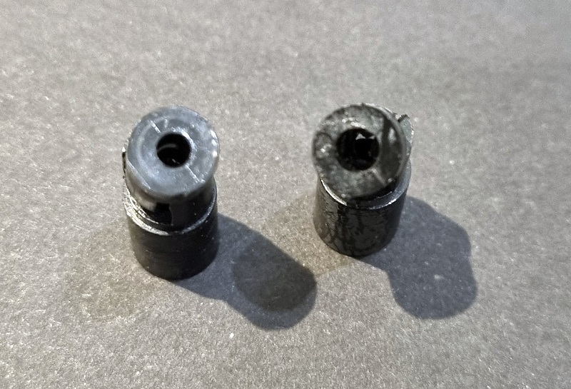
The universal itself consists of a ball and socket configuration and press-fits together.
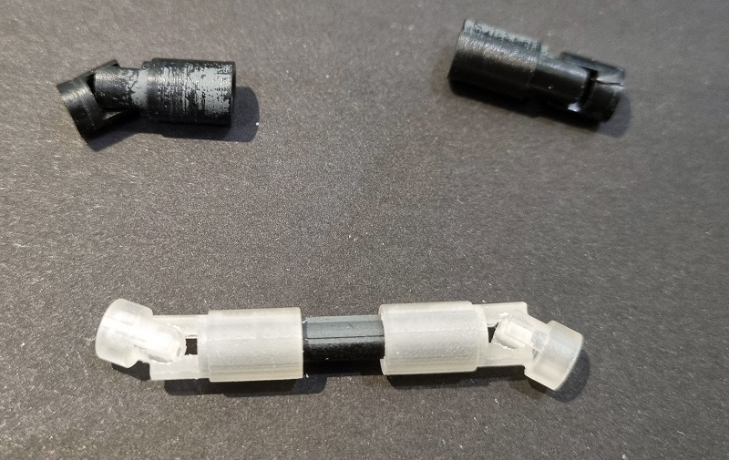
Using the original parts I was able to 3D model both ends of the universal, also taking into account the different metal shaft sizes. I needed to design the joint so it clips together and won’t easily pull apart, but is not such a tight fit that it cracks on assembly or prevents it from moving freely.
The 3D printed parts were printed in Shapeways Smooth Fine Detail material because it’s very accurate and hard, which is ideal for this use.
The two halves of the universal pushed together with a satisfying click and held in place, but allowed full movement. The ones shown here were the first test print and the tabs that hold the ball were a little weak. One did break so I thickened this up for the second test print.
The original driveshaft also fitted smoothly with its keyway.
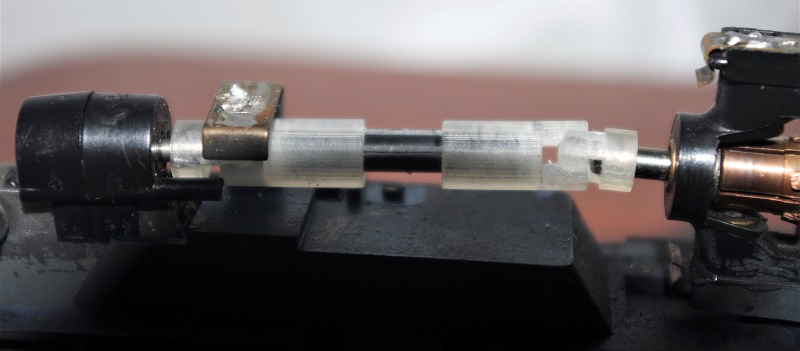
The last thing to do was fit the new universals to the locomotive. As with all my gears and parts that press-fit, the holes in the ends needed to be cleaned of 3D print residue before fitting. If this is not done the chance of cracking the new parts is high as they’re a tight fit by design. These were reamed out with a drill bit slightly smaller than the metal shaft. If it’s the same size the part will no longer be a press fit. You might be able to see in this photo that the tabs holding the ball are larger as these are the second test print.
The loco now runs as good as new and is ready to go back to the layout.
A set containing enough parts to replace all four universal kits can be found here.
If you have a part like this on a locomotive that you can’t find a replacement for, please get in touch and we’ll discuss making a new one for you.
As well as 3D printing model railway parts and kits I also build a lot of layouts for customers. Sometimes it’s a whole layout or sometimes, as in this post, I get asked to just do one bit. This week I wanted to share with you a recent job I did for a customer installing a pair of helixes in their new layout.
The customer is building a new layout in OO gauge (1:76.2) with staging yards on a lower level, 12.5″ (317.5mm) below the main baseboard, and they wanted to join both ends of the staging to the layout with a helix in each corner. Using 3rd Planit, which is 3D model railroad design software (https://www.trackplanning.com), I was able to draw out their baseboards and the track the customer had already laid in the staging yard. This allowed me to create a plan for the point work required, but most importantly shows the customer just how big the helixes were going to be.
As you can see the new helixes overhang the baseboard. The outer track on each helix has a radius of 22.5″ (572mm), the inner track is 20″ (505mm). The customer was concerned about the size as they’d expected them to be a lot smaller and fit onto their baseboards, but there are several good reasons for choosing these sizes.
Firstly is the availability of helix kits. I could design my own, cutting all the material and making a truly unique helix for this build, but that is very time-consuming and therefore costly, and as there are already several great kits on the market it makes sense to use one. The kit I used for this layout came from Model Railway Solutions, they provide two sizes of helix kits for OO and this leads to the second reason.
The first OO helix kit MRS produces is for 2nd & 3rd radius curves and the second kit is for 3rd & 4th radius, but what does that mean? The terms 2nd, 3rd, and 4th radius refer to the radius of Set Track, the curves often supplied with train sets, starter packs and sold separately by companies such as Hornby and Peco. Set Track is described as a range of rigid curves, straights, crossings and points (turnouts), made to the standard British geometry. With the curves, as the number gets bigger, so does the radius, and below you can see Peco’s Set Track curves from 1st to 4th radius. The key advantage is you can easily keep multiple tracks parallel around curves.
MRS’s helix kits have been specifically designed to match Set Track and for this build, I used the 3rd & 4th radius kit. But why choose that over 2nd & 3rd radius kit which would be smaller? The answer depends on what type of layout you’re building. Some larger locomotives have a minimum radius they can navigate and a few specify above the 2nd radius curve which is 17″ (438mm). So if you have large locos, which my customer does, they may struggle with the tight curves. But the main reason is the gradient.
These helix kits climb 3″ (76mm) with every revolution. As the radius increases the distance traveled increases and consequently, the gradient reduces. In the table below you can see how this works out.
Radius
Length of Full Circle
Gradient
2nd Radius
17″ (438mm)
108″ (2752mm)
2.762 %
3rd Radius
20″ (505mm)
125″ (3174mm)
2.395 %
2nd Radius
22.5″ (572mm)
141.5″ (3595mm)
2.115 %
Although the difference in gradient may not seem a lot, it can make a huge difference to a locomotive pulling a train uphill around a curve. My customer wants to run steam locomotives pulling at least six coaches so in order to give them the best chance the largest radius is recommended.
You may have noticed from the track plan at the start that the helixes are not mirrored but both climb in a clockwise direction. This is because trains in the UK run on the left so making them climb a helix in a clockwise direction means they are going up on the larger radius which is an easier gradient and coming down on the tighter radius which is slightly steeper. Model trains tend to find it harder pulling uphill than braking downhill.
The helix kits from MRS have three main parts. An entry/exit ramp, a first-level base kit, and a riser kit. The entry and exit ramp is a tapered section that allows the helix to start on top of a flat baseboard without modification.
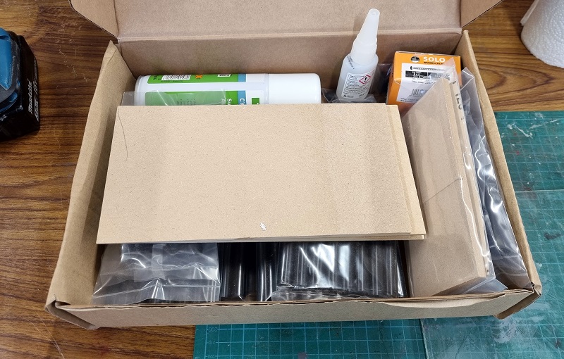
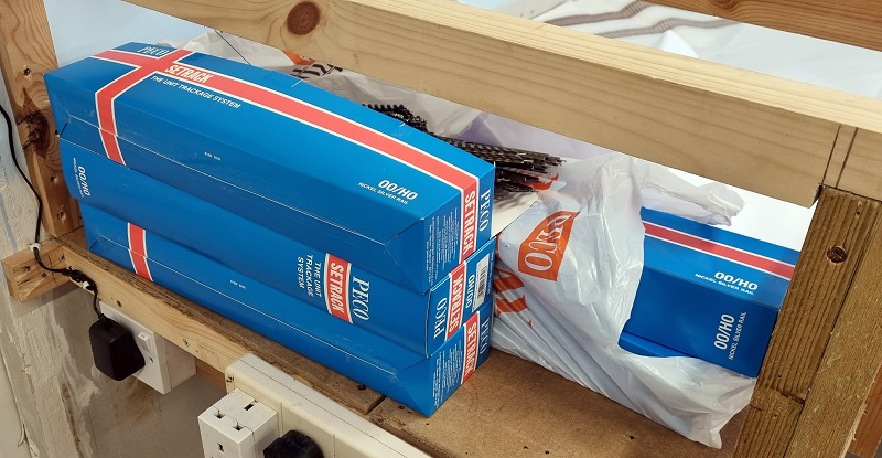
All the small bits come boxed together, the amount depends on your build. All these parts are for two helixes, each with four rotations.
In the box, you get 3D printed pillars ranging in size for the first level base kit, regular pillars, pillar caps, clips, superglue, superglue setter & cable ties. The box of screws in the photo are not part of the helix kit, they’re for fixing down the baseboard tops.
The actual helix deck is laser cut from MDF, each one has a stepped end to allow easy and accurate joining.
The one thing not included in the kit is the track and it’s amazing how much you need for a helix. I chose to use Peco Set Track and to build these two helixes I needed 64 3rd radius double curves and 128 4th radius curves (they don’t come in double).
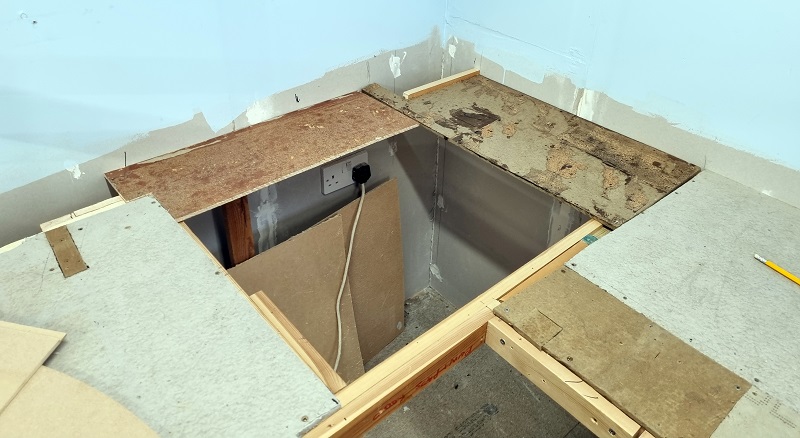
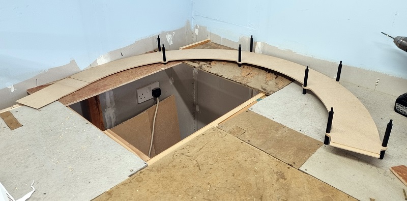
As I said at the beginning, the helixes are larger than the baseboards and although my customer had cut holes in their benchwork, extra support was going to be needed.
The support needs to be under the pillars of the helix and as long as it’s flat it doesn’t really matter what it’s made from. I was able to use the offcut material to make a flat surface, instead of buying new timber. The important thing to note is the hole in the middle, which is crucial as once the helix starts going in you won’t be able to reach the backtracks without it.
I added a triangular support at the front and some outcrops so each pillar has somewhere to sit.
In MRS’s first level base kit the 3D printed pillars are labeled A to H in ascending order. these sit under the helix and screw through the deck into a regular pillar. These first pillars are effectively the feet. They do have a thread in their underside should you wish to fix them down but the overall weight of the helix once complete will stop them moving.
But before we start fitting these the entry/exit ramp needs to be fitted and for this, the superglue is used along with the two bulldog clips.
Because the height between the helix decks is at a premium any fixing that protrudes above or below the deck is not useful so the joints are created by gluing the steps together and holding in place with the clips. This superglue holds fast in about 10 minutes. The spray is a superglue actuator that causes it to set instantly. I used it on this first joint but as for the later connections, I found I didn’t need to. Simpy putting superglue on the step, fitting the next board, and clamping for 10 mins with the clips worked perfectly.
The first 3D printed pillars can now be fitted along with the standard pillars. The standard ones on top act as the nuts, fixing the lower pillars. When screwing these in don’t overtighten them. You don’t need any tools, finger-tight is sufficient.
If the pillars are sat on a flat surface, the helix will climb at a constant gradient.
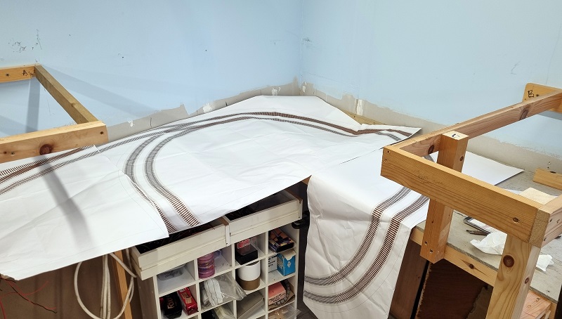
I test fitted the second deck section to make sure everything was in the right place, the end of the second deck fitted over the entry/exit ramp. Don’t fix the second section in place yet as you need to start laying the track onto the helix first.
With the helix in the right place and the second section removed, I put a few screws in the entry/exit ramp to hold it all in place, then started laying track. When using Set Track you instantly realize the benefit; it’s a perfect fit and holds a constant radius with ease.
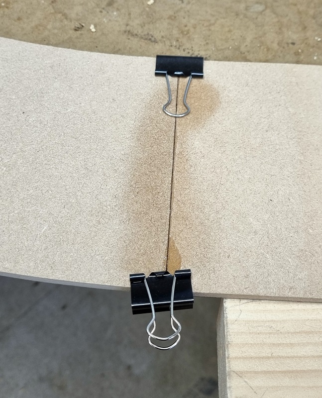
You may have noticed I haven’t used cork or underlay under the track, this is to maximize the height between the decks. I also chose to pin the track down. Because it’s Set Track and doesn’t flex you only need a few pins, which is good because there’s some bounce if you try and pin between the pillars, but close to them it’s okay. One thing to consider is the length of the pin. The deck is only 7mm thick so if a track pin is put all the way in it’ll stick out below and I guarantee you’ll scratch the back of your hand when cleaning the lower tracks at a later date! The solution is to put the pin in only enough to hold, then bend it over as shown below. As long as the pinhead is below the top of the railhead it won’t create problems with train clearance.
Something else to consider before you take the build too far is track power. Even on the inner line, a full loop is 125″ (3174mm) long. Times that by four rises and that’s a long way if you only have a power feed at the top or bottom of the helix; your loco may start to slow down as it gets further away from the power feed. My solution for this is to put a power feed to every level of the helix and solder the fishplates/rail joiners together for the other joints on that loop. In the photo below the power feeds are at the bottom of the photo. All the fishplates/rail joiners have been soldered with the exception of the ones at and above the entry/exit ramp.
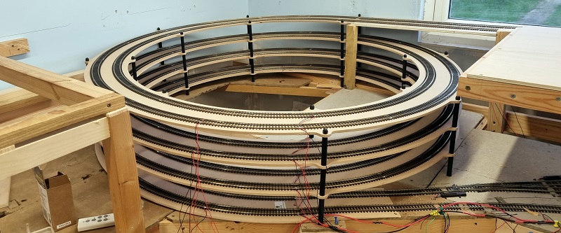
After several rotations, track laying and soldering as I go, the helix takes shape. Building from the inside is much easier, you can now see why that access hole was crucial.
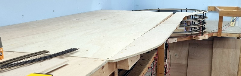
As can see above the top rotation is not a full circle, which would put the track facing the wrong way to enter the main layout, but that also means some of the elevation gain is lost. You may recall that the staging was 12.5″ (317.5mm) below the layout. The helix climbs 3″ (76mm) per revolution, so with just over three and a half it has only come up by about 11.4″ (290mm). To overcome this I build a ramp at the same gradient of the helix onto the new layout baseboards.
The track on this section will be laid with flexi track and have larger sweeping curves as it’ll be a visible section of the finished layout.
The cable ties supplied with the kit are used to hold the track feed wires together so they don’t snag on passing trains.
The helix on the other side is basically the same, although the top section is near the wall so the trains are again climbing on the outside of the helix. You can see the pillar caps holding down the top deck sections. These screw onto the pillars and act like a nut as well as covering the last of the exposed treads.
Again I constructed a ramp to make up the height difference that runs at the back of the new layout benchwork.
With all the track down and power connected, a quick test had to be done. The loco is a Heljan Class 28 Co-Bo Diesel.
These kits are a great way to add a helix to your layout and can be built in a variety of height combinations to suit your needs. They are also available from MRS for N Gauge Set Track and Kato Unitrack.
I build a lot of layouts in all shapes and sizes and I look forward to sharing some more with you in later posts.


You must be logged in to post a comment.