It’s been a nice weekend and it feels like Spring really is around the corner and the exhibition season is getting underway. So with that in mind I thought I would use this week’s post to share with you some of the exhibitions I will be at with the Gosport American Model Railroad Group’s layout, ‘Solent Summit’.
Fordingbridge Model Railway Exhibition on Saturday 16 April 2016.
This one-day show hosted by the The Rotary Club of Fordingbridge will be held at the Avonway Community Centre, 6 Shaftesbury Street, Fordingbridge, Hampshire, SP6 1JF, UK.
Poole Model Railway Exhibition on Sunday 6th November 2016.
This one-day show hosted by the Poole & District Model Railway Society will be held at The Poole Grammar School, Gravel Hill, Poole, Dorset, BH17 9JU, UK.
‘Tolworth Showtrain’ Model Railway Exhibition on Saturday 12th and Sunday 13th November 2016.
This two-day show hosted by the Hampton Court Model Railway Society will be held at the Tolworth Recreation Centre, Fullers Way North, Tolworth, Surrey KT6 7LQ, UK.
With all the excitement of my newly released Alco C-855, which you can find here, I have decided to make this week’s post nice and short.
I have lots of videos on my site; sharing with you what I’m doing and the exhibitions I’ve been to, but sometimes I simply take videos of my, or other club members’, trains running on our layouts and I don’t always have a reason to post about it in the blog.
So I have created a new section in the gallery called ‘Video Gallery’. In here you will find videos of our model trains listed by road and date. Some of the older ones are a bit jumpy but they do get better. When you click on a link it will open in a new full screen window where you can play the video.
As I take more I will add them to the gallery and on the home page there’s a new section on the right-hand side called ‘Latest Gallery Video’ so you can easily see when I’ve added something new. The link will also take you directly to the video.
The ‘Video Gallery’ can be accessed by selecting ‘Gallery’ from the drop down menu above.
This week’s post will be nice and short as I have just returned from the wonderful Brighton Modelworld show. We took our whole modular layout ‘Solent Summit’ and after three days of manning our exhibit I must say I’m a bit worn out.
One thing I did bring back from the show was the need to add another page to my website. A lot of people wanted to know how we created our rock faces, or how we got locomotives to work in certain ways. As I have already written about some of these topics I have decided to add a ‘How Tos’ page to the gallery which will list all the topics I have covered so far. The posts under this heading will only be the ones where the focus of the post is how to do something, so any posts where I am simply sharing with you the results will not be included. As I write more ‘How Tos’ they will be added to this page.
You can find the page here or by selecting the gallery page in the drop down menu above.
The Brighton Modelworld event was a fantastic show but as I was so busy running the layout for three days I didn’t get any pictures of it. However I did manage to capture three videos of my trains running on the layout.
First we have the Southern Pacific Overnight express powered by four black widow F7s. These are the ones I wrote about in my ‘How Tos’ post ‘Converting An N Scale Bachmann F7 to DCC’. The train is crossing the river Warsash on the Warsah Wye trestle.
Secondly we have the Southern Pacific Sunset Limited also crossing the Warshah Wye trestle. The three Alco PA’s have the assistance of a 4-6-4 steamer as the train battles the grade.
And thirdly we have a pair of Santa Fe DT6-6-2000 transfer locomotives working a train of perishable box cars through New Mills on their way to the SF East End yard.
In next week’s post I will be getting back to 3D printed products and sharing with you the first 3D printed N Scale Alco C-855.
In this week’s post I will show you how I modify Peco points or turnouts to use with DCC, and explain why I make the changes.
Peco make a variety of points in all the common scales and I have used them for many years. Personally, having used them for American and British trains in both N and OO scales, I think they are the best ready-to-run points available. However I always make modifications to them rather than use them directly out of the packet. You can use them directly from the packet and they will work just fine, but I find for lasting reliability a few improvements are needed. For my example I am using some brand new OO/HO large radius points as shown bellow.
This point, as it states on the packet, is an Electrofrog. This means that the area where the rails cross, commonly called the frog, is metal, allowing the maximum amount of electrical connection with the pickup wheels of your trains. Peco’s other points are called Insulfrog and these have a plastic frog. Insulfrogs are the easiest to install because the plastic frog isolates all the rails so you don’t have to make any electrical brakes in the track or do any special electrics. But the downside is the large electrically ‘dead’ section over the plastic frog which can cause stalls with slow-moving or small trains. So I always use Electrofrog points.
To use the point shown below all you need to do is connect the two inner rails using a plastic rail joiner.
Below is an extract from the back of the Peco packet showing how to wire this up for DC or DCC power. With DC power if you don’t include the isolating rail joiner the point will also switch the power on and off in the two sidings. It does this by making the polarity of the rail connected to the frog the same as the stock rail (outside rail) for the route that is not selected.
As I said before, using this point directly out of the packet and connecting it as shown above should work just fine but the drawback is how the power is delivered to the frog.
As supplied, the frog relies on electricity travelling from the stock rail into the point blade via the contact of the two surfaces. Then it travels up the blade rail to the frog. When the point is changed the other point blade makes contact with the other stock rail and the power is fed from that side, also reversing the polarity of the frog. The point throw bar has a built-in spring which keeps pressure on the point blade, holding it against the stock rail. When the track is new and shiny this is fine, but over time dust and grime will get inbetween the two and the electrical connection will become weaker. And if you weather and ballast your track this connection will probably stop working altogether. It can be cleaned by using a piece of fine sand paper or a file but this is not an ideal solution or a permanent fix. Plus the point blade can easily be bent and it’s next to impossible to get it back to straight again.
There is also another problem that can occur. Electricity will always follow the path of least resistance. For example if you had a bit of track with two power connections and one was badly soldered, although you can’t tell, the electricity would flow through the good connection.
So imagine you had a point connected as described above with dirt or dust inbetween the point blade and the stock rail; it’s just about working and the locos will travel over it. But the train you are pulling has a coach with a light in it powered from the track and there are pick-ups on all wheels of the coach. As the coach spans the point blade, i.e with one truck or bogie on the stock rails and one on the frog the electricity will elect to travel through the coach and not through the points. If the lighting circuit in the coach is only a 1.3v LED with a tiny current draw it will not be designed for a lot of power and there is a chance that it will blow. This could happen as the full voltage being pulled by the loco is now passing thought the coach circuit. With a DCC powered layout it may also have the current from several locos running through the coach and I have seen a coach that was parked across such a point that got so hot that the truck actually melted.
So now you know why I modify the points, but what do I actually do?
The first step is to decide how else you can power the frog because it needs to be fed from one stock rail or the other, depending on the direction it’s set in. This can be done in a variety of ways. Peco make an accessory switch that can be fitted to their point motors to power the frog. Seep point motors and Tortoise slow motion point motors both have a built-in switche that can be connect directly to the frog. Peco also make an electronic switch called a smart frog, this will only work with DCC. The smart frog is connected to the power bus and the frog. As a train wheel makes contact with the frog, if the polarity is wrong, it will detect a short faster than the DCC control system and reverse the polarity, allowing the train to continue as if nothing was wrong. Other companies like Tam Valley make the Frog Juicer which works in a similar way to the Peco smart frog.
Simply feeding the frog will greatly improve the performance of the point because the power will run up into the frog and back down the point blades but there’s still an issue. The point blade that’s not touching a stock rail will be a different polarity, as both point blades and the frog are all the same, and there’s the possibility with wide flanged rolling stock that a short could happen as a train passes by. To overcome this Peco have given access to the connecting wires on the underside of the point. In the picture below you can see two small slots in the plastic, each with a connecting wire in. These wires join the frog to the point blades. I remove these wires; as they have been spot welded in the factory you can simply put a small flat ended screwdriver into the slot next to the wire joint and twist. The spot weld will break, repeat for the other end and the wire will fall out.
The problem now is the point blades are again reliant on the contact with the stock rail, however Peco have made this easy to fix. As you can see in the image below, next to the slots where we removed the connecting wire, they have omitted some of the plastic allowing access to the underside of the stock rails and the top of the point blades. On older points this access is not there but can easily be made with a sharp knife.
Using a soldering iron I tinned the underside of the rails with solder.
I then stripped the insulation off some solid core wire and cut it into strips, the same length as the distance between the stock rail and nearest point blade.
Then I placed the wire over the gaps and used the soldering iron to attach each end to the tinned area.
Repeating this on both sides means that the point blades are permanently connected to the stock rails.
And there you go; the point is ready to be installed on the layout. There’s no danger of a bad connection to the point blades, or a short between the free point blade and the stock rail and the frog is powered via a switch. This point will be electrically reliable even when weathered and ballasted .
So although Peco points work straight from the packet, in my experience making these improvements up front will make your layout more reliable and keep your trains running well for years.
Recently I have been working on a British outline OO layout which had some working semaphore signals. Sadly some of these signals had suffered some electrical damage which rendered their control circuit boards inoperative. In this post I will be sharing with you a few simple methods of repairing Dapol semaphore signals.
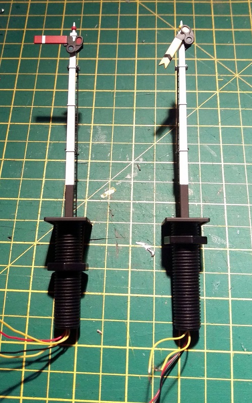
The Dapol semaphores, as shown below, are nice looking signals and have a fairly basic drive system which is self contained in the tube below the signal. Above ground there is a nicely detailed rectangular post with the rotating arm on top. The arm is connected via a crank to a push-rod that runs down behind the post. You will be able to see this in some later photos. The glass lenses in the end of the arm are transparent and a small LED shines through creating the correct color.
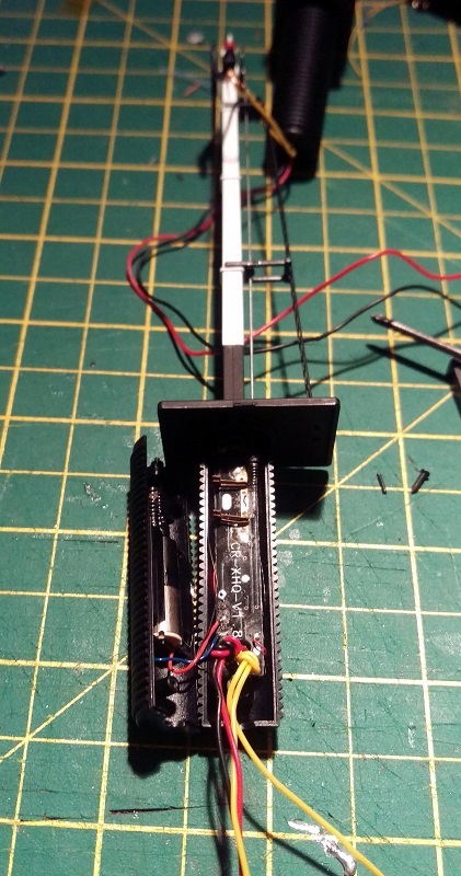
Below ground is where all the clever parts are. Interestingly the drive system on these OO signals is also used for their N Scale signals; Dapol have simply changed the size of the signal on top. In the large threaded tube at the bottom of the signal is a circuit board, electric motor, gear rack and worm gear. After the large nut has been removed there is a tiny screw at the base of the signal which holds the two halves of the tube together. Once that has been removed the tube can be separated.
The motor is in the left half and the circuit board is in the right. You can also see the push-rod that runs up behind the signal pole in front of the ladder. And if we zoom in you can see below the push-rod is a spring. This spring is attached to the push-rod and when it’s moved up and down the signal arm moves up and down.
The two pairs of metal contacts are part of the circuit board; as the motor spins the worm gear it drives the rack either up or down pushing the rod. A spigot sticking out of the rack touches one of the pairs of contacts creating a circuit and telling the circuit board that the rack is at the end of its travel. However as the circuit board is damaged these are of no concern to us.
As new, the signals work by providing 16v AC power to the red and black wires. This powers the circuit board and the LED at the top of the signal pole. Then by simply touching the two yellow wires together, using a momentary Push-To-Make switch, the signal will change. Even when you let go of the switch the motor will keep going untill the rack gets to the end of its travel.
On the first of the two damaged signals only the motor drive function was inoperable, the light still worked when 16v AC power was applied, so the circuit board was still producing low voltage DC which is also needed to drive the motor. In the picture below you can see the wire connections. The red and blue are the DC feed to the motor. The tiny red and, hard to see just above the yellow, tiny black are the LED feed that run up inside the signal pole. The big red and black are the 16v AC power in and the yellows are the activators.
So to fix this signal I removed the motor wires from the circuit board and extended them by soldering on some more wire and heat shrinking the joint.
Then I removed the yellow activator wires from the circuit board and added a pair of wires to the LED feed connection points.
The signal was then reassembled with the new wires coming out of the bottom.
The next step was to take the low voltage DC power, coming from the new blue and green wires, out to the layout control panel. Then, using a momentary double pole double throw (DPDT) switch, return the power to the motor wires, in positive or negative, to make the motor go one way or the other. The DPDT switches I use are toggle switches as shown below.
These have six connections on the bottom. When it is thrown one way it joins the middle pair to the top pair and the other way joins the middle pair to the bottom pair.
So, if the incoming low voltage DC power is connected to the bottom pair, then reversed and connected to the top pair, throwing the switch one way or the other will reverse the DC power.
The motor is then connected to the middle pair of terminals, not shown above, and the signal can be manually controlled. My apologies as I got a bit carried away with the work and so didn’t take any more photos of this particular signal. As the switch is a momentary, when you let go it springs back to the middle and stops the motor. There’s no danger of pushing the motor too far as when the rack gets to the end of its travel it simply stops, although the motor keeps spinning. The spring on the end of the push-rod, and there is another one on the bottom of the rack, supply just enough pressure to make the rack re-engage with the worm gear when you want it to run the other way.
This fix, although functional, is not ideal as you are still relying on a damaged circuit board and all the small parts inside the tube. Plus you have to hold the switch untill the signal has reached its position.
The second fix I have for these signals is a bit moire drastic but I think in the long run is a more durable solution.
The second signal’s motor and circuit board had failed so I removed all of the parts from inside the tube. Sadly the LED had also blown on this particular signal so the wires for that will go as well.
As all the points on this layout are powered with Seep point motors it made sense to power the signal in the same way. Seep make a special point motor with a latching spring which is designed to work with hand-built points that don’t have a latching spring of their own. The latching spring means the motor will stay in the required position even though the spring on the push-rod will be pushing back. This latching point motor was mounted to a ‘Tee’ shaped mount as shown below.
There is a slot for the motor throw bar to pass through and the large hole above the throw bar is for the signal tube.
You can see the latching spring under the motor cross-bar.
As the tube on the bottom of the signal was now empty it could be reduced in length; this was also necessary so it didn’t hit the throw bar. The last thing to do was to connect the throw bar to the signal push-rod. However there is a problem in that the point motor movement is more than the signal needs, and as the point motors are powered by Capacitor Discharge Units the motor bangs over very hard which will damage the signal.
To counteract this I made a very basic omega ring out of thin nickel rod. One end was superglued into the spring on the bottom of the push-rod, the other was looped around the motor throw bar.
Although basic, this omega ring absorbs the sudden shock from the point motor as well as any extra movement while still supplying enough force to move the push-rod. The two shorter tube halves were glued together and the ‘Tee’ mount was screwed to the underside of the layout. The signal was then put though the hole in the layout and mount. Before the large nut was tightened up the signal could be tilted to one side to alow the omega ring end to be slid over the point motor throw bar. Once tightened up the omega ring could not slide off the throw bar, but as an extra measure I glued a small washer onto the end of the rod.
This second fix was a lot better because the signal changed quickly with a single touch of the switch and any wiring is the same as a standard point motor.
These signals have also been modified in a similar way with servo motors which gave a very nice smooth action and this might be something I will try next time. If I do I will share it with you.
For this week’s post, being the first post in 2016 and because I did it last year, I thought I would take a look back over the 3D printed and metal products, how-tos and exhibitions from 2015.
January saw the release of my O scale Union Pacific excursion train tenders. These had already been released in N Scale and HO but to scale up to O was an interesting challenge. Both Joe Jordan and Jim Adams were made available and they can be found here.
These were a lot of fun to work on after all the N Scale models and they looked fantastic. Only the bodies and detail parts were 3D printed as they ran on Lionel trucks and chassis. The Lionel parts have plenty of weight, which is very important with O Scale.
The other new release for January was my N Scale dummy chassis for Atlas’ Alco C-628 & C-630 body shells.
This chassis was also made available with the option to fit the original circuit board for lighting using a circuit board clip as shown below.
This chassis is ideal if you have purchased one of my Baldwin DT6-6-2000 or RT-624 kits and have a spare shell left over from the donor locomotive. In the line up below only the middle locomotive has a powered chassis, the other two are dummies using my chassis kit. The kit can be found here.
In February I released my replacement gears for Rivarossi F9 O Scale locomotives.
These replace the original drive gears on the axles that have a tendency to split. Below you can see a set that has been fitted to the loco.
The Rivarossi F9 chassis is popular with O Scale modelers and here it is under a GP7 body shell on Mike Dobson’s home layout. The incline is fairly steep so it’s a good testament to the strength of the gears. They can be found here.
February also saw the start of my C-855 project which you will be seeing more of very soon.
March brought detail parts such as my replacement N Scale horns and these came in a variety of styles.
These are now available here in several configurations and there will be more coming this year.
April introduced my N Scale Etched Chain Link Fencing. The fencing is made from stainless steel sheet and is currently available in three configurations which can be found here.
Because of the new fencing and other metal products becoming available I created an Etched Metal Additions page in the shop.
Shapeways also announced their new higher quality 3D printed material FXD.
This new material has a 16 micron layer thickness which is sharper and finer than the FUD which has a 29 micron thickness. The FUD is still a fantastic material so, as the FXD is more expensive, I now offer my models, where appropriate, in both materials.
May brought more detail parts such as the replacement eccentric rods for MRC/Rowa N Scale 2-8-4 locomotives.
These are designed to simply clip in as a direct replacement, as you can see below.
June introduced some more N Scale replacement horns and I started sharing my work on my modular layout sections, beginning with my 3D printed trestle bridge deck.
You can read more about the trestle parts in part 1 here and part 2 here.
The C-855 project also took a step forward with its metal chassis extension parts.
You can read more about the chassis extension here and here.
With the summer getting underway, July was a quiet month for new releases, with only a set of etched brass name plates being released for a OO gauge Schools class 4-4-0 locomotive.
The rest of the month was mostly taken up with working on my modular layout getting ready for exhibiting, and I did a how-to on casting your own rocks, which you can read about here.
In August I gave some demonstrations including how to create cheap but effect Nut, Bolt & Washer details for trestle bents which you can find here.
You can find my how-to on using your rocks to build river & railroad canyons here.
And how to paint your rocks which you can find here.
And to close out August I released my brass Addition kits for my P42 mirrors and GP7/9 detail parts.
They can both be found in the etched metal Additions page here.
September brought some more replacement parts and this time it was a crank pin for a Minitrix 4-6-2 Britannia. You can find the part here.
I also did two more demonstrations; one on how to ballast track which you can find here.
And one on how to make your own Talus and rock fall for river beds which you can find here.
November was mostly taken up with exhibition reviews (see towards the end of the post) but I did share with you my new design for 3D printed speaker enclosures which you can read about here.
These will be available shortly but for now you can see some examples of the working prototype here.
December is normally a short month for me and I shared with you a how-to on adding resistors to N Scale wheelsets for track detection.
As well as all the new products and how-tos I also visited a few exhibitions and a home layout and you can find them all below.


 The problem now is the point blades are again reliant on the contact with the stock rail, however Peco have made this easy to fix. As you can see in the image below, next to the slots where we removed the connecting wire, they have omitted some of the plastic allowing access to the underside of the stock rails and the top of the point blades. On older points this access is not there but can easily be made with a sharp knife.


 You can read more about the trestle parts in part 1


You must be logged in to post a comment.