Painting and Finishing the UP Water Tenders

Now all the model errors have been sorted out and I have a successful test print of the UP’s rebuilt water tenders it was time to paint and decal them in order to finish the model.

For this I handed the model over to Bob Norris who also painted the DD35 models.  He first washed all the parts again in warm soapy water to remove any oils that may have built up on the surfaces due to people handling the model.  Once dry, he glued on the headlights and tool boxes; these can be glued on at later stage but as they are going to be the same color as the top of the body it makes sense to do it now.

Once all the glue had dried, the main body, chassis and ladders where sprayed with Humbrol’s Acrylic Sea Grey from a can.  As well as being a good primer this is also a great match for UP’s Harbor Mist Gray.

Next comes the yellow on the main body and Bob brush-painted this using Badger’s UP Armor Yellow. This paint is very thin and three coats were required to cover the primer with an even color.  For the forth and final coat Bob added a drop of PollyScale’s Signal Red into the UP Armor Yellow, this darkened the yellow to make it a perfect match to the yellow of the Kato City Of Los Angeles passenger cars.

Once the paint had dried he sprayed the whole body with Testors Glosscote; this sealed the paint and gave a nice finish.  The red lining between the gray and yellow is a red strip decal.  The other decals came from Circus City Decals & Graphics who provide a set especially for this model and can be found here.  Once the decals had been applied and set, the ladders were glued on.  The final stage was to spray the body with Testors Dullcote which removes any areas of the decals that show up shiny against the body and forms a coating to protect them.

Bob then painted the trucks with Humbrol’s Silver.  He also used a dab of this to paint the light lenses in the headlights, after which he put a drop of CA glue over the silver paint to form the actual lenses.

And here is the result

UP Water Tenders 1Several others who have purchased the kits have also sent me some pictures of the finished models and work-in-progress.

Here are Jim Reising’s UP water tenders.

Jim Reising - Water Tenders

Jim used spare handrails from a Kato Dash 9 diesel locomotive to replicate the grab rails on top.

Brian Stewart also sent some work-in-progress shots of his water tenders.

UP Water Tender 4 (Brian Stewart) UP Water Tender 3 (Brian Stewart)

Brian used brass wire to make his grab rails.

UP Water Tender 8 (Brian Stewart) UP Water Tender 7 (Brian Stewart) UP Water Tender 6 (Brian Stewart) Mark Peterson, who was also the inspiration for this project after suggesting someone make these water tenders available, used Evergreen .020″ styrene rod for his grab rails.

UP Water Tender 1 (Mark Peterson)

UP Water Tender 3 (Mark Peterson) UP Water Tender 2 (Mark Peterson)

UP Water Tender 4 (Mark Peterson)

Mark also has a video of his excursion train, complete with water tenders roiling through Hope, MN.

You can read more about Marks layout, ‘A Season In Hope’ and his adventures with the water tenders on his website here.

Mark’s original request however was for the UP water tenders as they appeared before they where rebuilt in 2007, so here is a sneak preview of what is coming next.

UP Water Tender (Turbine) Type 2

The test print for this car is in the post as I type and I’ll share with you what it looks like in a future post.

Checking the UP Water Tender 1st Print

With the 3D model of the UP re-built water tender complete and successfully ordered from Shapeways, a review of the actual model was needed to check everything was okay before making it available to all.

When the test print for the tender arrived it looked fantastic although it was hard to see all the detail due to the waxy residue left over from the print process, and the fact that the FUD material is almost transparent. This also makes it very hard to photograph but putting it onto a black background really helps. Here are all the parts for the kit laid out after a quick wash in warm water.

UP Tender Water Tender Kit
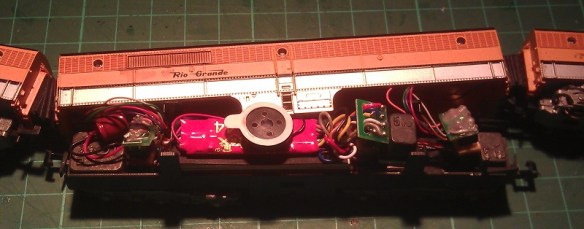
The water removed a lot of the residue but it would still need to be soaked in Goo Gone for 24 hours to totally eradicate it.  At this stage the detailed parts start to become easier to see as well as the few areas which had not printed correctly.  For example, on the trucks at the bottom of the photo you can see the air cylinders and the pipes running back into the trucks; there is a gap between them that should not be there.  Looking back at the 3D model it became apparent there was an error which did not show up easily. This was fixed before releasing the model.  There were also some other minor issues with the piping, once again all traced back to the 3D model; these were also fixed.  One of the most noticeable things in this photo is the chassis which has a bow in it.  This chassis is very thin to help keep the cost of printing the model down, however is not a concern as this particular model is designed so the strength comes from the main body, which is very strong due to the multi-curved surfaces. The chassis straightens out when put into place.  Once the model is cleaned, painted and the trucks have been attached, the chassis is designed to be glued in place making a very strong, complete body.  For reference, should you receive a chassis, or any other part, that is bowed more than is shown in this picture, it can be easily be corrected using hot water as described n this previous post.

Another important part to check are the trucks to see how well the wheels fit.  This model has been designed to take Micro-trains 33″ wheel sets and, learning from experience, I don’t recommend trying to fit Atlas 33″ wheel sets as they are a lot wider and I broke one of the sides of the trucks clean off.  This was not all bad, I discovered that this material can be repaired very effectively with Loctite Gel Control super glue and it highlighted a weak spot in the trucks which was also fixed in the 3D model.  The Micro-Train wheels sets fit perfectly with a satisfying click.

Another problem I foresaw was with the ladders.  In themselves they are very small and consequently could easily be misplaced, either whilst being handled by Shapeways or by the modeller as they are cleaned ready for painting.  I didn’t want to make them a part of the main body as this would make it even harder to paint so I joined them together on a ring.

Once all the parts have been cleaned the ring can simply be cut away releasing the ladders. This is something that can be achieved only through 3D printing; no other manufacturing processes can produce parts joined together as one that don’t actually touch each other.  This also helps Shapeways guarantee they have put the right parts in the right box. Customer feedback on this has proved this works.

I found when test fitting the Micro-Trains body mount couplers a slightly bigger space would help as they where a tight fit so this was changed in the 3D model.

Once the parts had been soaked in the Goo Gone and properly cleaned they were test fitted again.  Everything fitted and worked.  Below you can see the model on a test track between a Rivarossi Challenger and a steel box car.

UP Water Tender After Goo Gone

The tool boxes on top are still loose, as are ladders, flag plates and headlights.  Once painted these can all be glued on as well as securing the chassis.

With all the updates made to the 3D model it is now released for sale and you can find it here.

The next step is painting which is done by Bob so I’ll share that with you!

Drawing the UP’s auxiliary excursion train water tenders for N Scale

The Union Pacific railroad heritage fleet currently runs two of their preserved steam locomotives on regular excursion trips and, with the very much anticipated Bigboy No. 4014 re-entering service in the next few years, the modelling of the excursion train will become even more popular. With Athearn’s new N scale Challenger and Bigboy locomotives, or even the former Rivarossi models, and the Kato ‘City of Los Angeles’ cars, this can easily be done. The one important thing missing is the extra water tenders now always used for the long trips.

Ever since the switch from steam power to diesel the supply of water along the railroad has all but dried up; often you can see local fire department filling the excursion train locomotives water tanks with their pumping equipment at stops along the way. To combat this UP have created auxiliary water tenders which hold more water than the engine’s own capacity and greatly increases the range of the excursion trips. Currently, my understanding is, the UP has four auxiliary tenders in the heritage fleet.

Here is UP 844 in Oakland, California in 2009, accompanied by one of the auxiliary tenders whilst on an excursion trip stopover.

UP844 April 21st 1 UP844 April 21st 2 UP844 April 21st 3 UP844 April 21st 4 UP844 April 21st 5 UP844 April 21st 6

These tenders started life as regular coal and water tenders for the 800-class steam engines until the engines where decommissioned due to the new diesels. However when the new 8500 class gas turbine locomotives, built by General Electric, started being used by the UP, the need for tenders to hold their bunker C fuel oil was created and the old 800-class tenders where recycled for this purpose. Because the bunker C fuel oil needed to be kept warm so it could be pumped as a fluid, the tenders were fitted with a heating system and a second metal skin for insulation and to cover the system. When the UP retired the 8500 Gas Turbines the tenders remained in storage until the heritage fleet commandeered them for the excursion trains. The heritage fleet used the tenders in this configuration until 2007 when two were rebuilt removing the heating system and the second skin. This increased the water capacity by 3000 gallons to 28,000 gallons. These two tenders were christened UPP 809 Jim Adams and UPP 814 Joe Jordan after two retired steam fitters from the UP repair shop.

I wanted to produce models of both versions of the tenders so I could replicate both periods (pre and post 2007). I decided to start with the newest incarnation and set about producing a 3D computer model.

UP Water Tender10

I used a mixture of images and drawings from the internet and books to get the correct dimensions.  There’s a 8500 gas turbine and tender at the Illinois Railway Museum and they have lots of good pictures, as do Wasatch Railroad Contractors, who did the conversion on water car UPP 814.

UP Water Tender8

Some elements were simply too small to be reproduced in N scale, such as the handrails that run along the top and up the ladders.  I decided that it would be best to add these using brass wire at a later stage.

UP Water Tender9

To make this easier to paint I separated some of the detail parts from the main model body.  The ladders, roof tool boxes, headlights and flag plates are all loose parts, as are the trucks, chassis and bolster pins.  Here are the parts laid out ready for the first test print.

UP Water Tender6

The body has been designed to take Micro-Trains body mount couplers.  The bolster pin that holds the trucks to the chassis has also been positioned off centre, unlike the prototype, so that the trucks can be removed without removing the wheel sets.

UP Water Tender7

In the next post I will show you how it came out and what improvements needed to be made before it was ready for the final print.

Making your own DCC plugs and connectors

With a lot of DCC installations, particularly on older locomotives, the wires and plugs need to be modified in order to make them fit.  This often creates weak wire joints, especially in areas where the wires can move, so I wanted to find a way to protect these areas.

Recently I have been installing single DCC decoders in multiple locomotive consists; below is a set of Con-Cor Alco PA/PB units.

Con-Cor DRGW PA-PB-PA

Both the PA (Cab units) are powered and the PB (Cabless booster) is a dummy.  Inside the PB I have installed a Digitrax sound decoder with the wires running through the corridor connections to the two motors, similar to the Con-Cor EMD E7 DCC installation from my previous post.

I decided to add connectors into the system so I could separate the units if required, which also made it easier to trace any faults such as short circuits whilst testing the units.  Below is an image of the wire harness before it was fitted into the PB unit.  The bit in the middle is a socket for the DCC decoder with a homemade plug fitted into it which joins all the wires together for DC operation and testing.

PA Wire Harnes

Although the wires are soldered to the pins, they are still delicate and given the limited number of strands, individually the wires could easily be broken off.  To prevent this from happening, after I had tested the harness I painted the soldered connections and wire ends with a PVA glue. I used a cheap PVA designed for school projects from a local art shop. The PVA went on well and as it went tacky it held in all the pockets between the wires.

PVA Socket

I also added a second coat a few hours later to ensure I had good coverage.  Once dried it went clear and held all the wires in place, plus it gave them a coating to prevent any shorting.  I also did the same thing with the plug ends.

PVA Plug

Once everything is assembled the PA units can be separated from the PB unit by simply pulling the plug without risking damage to the soldered wires at their weakest point.

Con-Co PA-PB with Sound

Another advantage of this is a second PB dummy unit (or possibly a powered unit) could be added into the consist as long as it had the same wires and plugs running through it.

Here is as short video of the D&RGW Prospector pulling into Solent Summit station.

Sadly the sound decoder speaker is not as loud as the noise from the older Con-Cor motors which drowned it out, but that is a challenge for another post.

Cost-effective DCC installs for consisted locomotives

With Digital Command Control becoming ever more popular more clubs and home layouts are switching to it, but it can be quite costly to convert all your locomotives to DCC, so I’ve been looking at ways to make this cheaper.

A lot of US outline trains run with several powered units forming one consist and using one DCC decoder for the whole consist is my plan.   A good example of this is the set of powered EMD E7 units below.

IMAG0242

These models, made by Con-Cor, will always be run as a set and although the middle unit is a dummy locomotive the other two would normally both require a DCC decoder.  This is because there’s no electrical connection between the three units and, despite both being good runners, the two powered units run at different speeds.   This is a problem because one locomotive will always be pushing or pulling harder than the other.

Below is a video of the two powered units (without their shells) on a DC test track.

Clearly you can see that the nearest locomotive runs much faster than the other.  This is because the motor in the nearest locomotive has a much lower starting voltage.  If both locomotives had their own DDC decoder fitted they could be speed matched.  This is done by adjusting the DCC configuration variables using a DDC controller or a system plugged into a computer.  Doing this effectively alters the starting voltage of one or both of the locomotives to make them run at the same speed.  The drawback of this is that you would still need two decoders, an understanding of how to do this, and, if the train is run on a DC layout, the problem would still be there as the CV settings do not have any affect under DC control.

An alternative is to increase the starting voltage of the faster locomotive motor.  An easy way to do this is to add some resistance into the electrical circuit, but this can cause other problems as resisters do this by turning the unwanted power into heat.

A better way is to add a diode into one of the motor feeds.  A diode works by only allowing DC power to flow in one direction whilst causing about a 1.5 volt drop.  Of course this would mean the motor could only run in one direction so a second diode will also need to be used at the same location but positioned in the other direction.  This meas that the power going to the motor will always pass through a diode irrelevant of the direction of the locomotive but with a reduced voltage.

Depending on the speed difference you have between the two locomotives, you may need to use more diodes to give a bigger voltage drop.  For this particular pair of locomotives three diodes, giving a voltage drop of 4.5v, were required in order to make the two motors run at the same speeds.  There is room between the main chassis and the shell so I constructed the diode circuit to fit in this space using 6 diodes; three for each direction.

Diodes E7 Chassis E7 Chassis With Diodes

E7 Chassis Ready For Shell

With the diode circuit fitted into one of the motor feeds you can see the difference in this video, also on a DC test track.

Now the two power units run at the same speed I can use one DCC decoder to power both motors.  It is important to select a decoder that has a maximum current capacity that is more than the combined current draw of the two motors.  This can easy be checked with an amp meter.  With the shell removed from your locomotive, connect a DC controller to your locomotive, passing one of the motor feeds through the amp meter.  Then using your fingers, prevent the motor from turning and turn on the controller.  The motor will try to turn but will stall as you have it clamped in your fingers, and the amp meter will measure the maximum current drawn by the motor.  Do this with both motors and add the values together.  If the combined value is less that the maximum current capacity of your chosen decoder then it will be ok.

As there’s lots of space inside the dummy unit the DCC decoder is installed in there.  I used a Digitrax decoder and ran the wires through the corridor connections.  This causes a small problem in that the three locomotives are now permanently fixed together by wires; should they come uncoupled it could put too much strain on the wires and cause damage.  To solve this the couplings have been replaced with 3D printed permanent couplings.

Fixed Coupling 1

These have the same ends as Rapido-style couplings and are a direct replacement using the same spring.  A flexible corridor connection was also made using black foam and corrugated card.

E7 Coupling 1 E7 Coupling 2

The chassis for the dummy unit is actually a different make, Life-Like, but this is a bonus because it has power pickup on the trucks.  All three units have power pickups that can now be connected together which greatly improves the performance of the combined locomotives.  So this three unit EMD E7 set is now DCC converted using only one DCC decoder.  Here they are pulling ‘The City Of Los Angeles’ on the GAMRG’s layout at the 2014 NMRA winter meet in Benson, UK.

Hopefully this will save you money on upgrading your locomotives to DCC, which can become incredibly costly given some size layouts and train collections. I’ve been experimenting in a similar way with a sound decoder; if I make any notable progress I’ll post it here.

Benson Winter Meet 2014 – NMRA (BR)

On the weekend I was at the National Model Railroad Association (British Region)’s winter meet and model railroad exhibition in Benson, Oxfordshire, UK and I wanted to share some of the layouts with you.

This is the first exhibition on the calendar for the NMRA (BR) and it was also my first visit. The show is a one day show only, but after talking to several of the regulars it appears to be a very popular show and this year was no exception despite the bad weather and flooding we have been having over the last week.

I wasn’t just visiting the exhibition, I was there with my club, the Gosport American Model Railroad Group, and we had brought part of our modular layout, Solent Summit, along for the day.  So, in between running trains and chatting to the public, I had some time to look around a few of the other layouts and stalls.

NMRA (BR) Benson 2014 Overall

The hall in Benson was a nice size and was filled with layouts and stalls and although there was also more upstairs I didn’t make it that far as I had trains to run!

Here are some of the layouts that were at the exhibition;

Red Hook Bay 1

This is a beautifully detailed HO layout based in Maine, USA in a fictitious setting.

Red Hook Bay 2

Everywhere you look there is fantastic detail and even though I have seen it before I keep spotting new things such as the crab nets on the dock.

Red Hook Bay 3

The layout consists of a small station and yard with a train ferry entrance.

Red Hook Bay 4

For me, the best parts of this layout are the buildings and scenery.

Red Hook Bay 5 Red Hook Bay 6

In particular I loved the lighthouse and the detailing of the action around it around it.

Red Hook Bay 8

Sankei 1

This is a Z sale layout by Peter McConnell. The layout is a city scene  set in Japan with an electrified two-track main line running round to a storage yard at the rear.  In the front there’s a station and yard scene. A branch line runs out from the station to the yard which is not electrified.

Sankei 4

The station has three platforms, the nearest two being an island platform on the main line.

Sankei 2

Leaving the station the main line and branch run parallel around to the yard.

Sankei 3

I’ve never worked in Z scale so I am often impressed by the level of detail, as I was with this one. The trains ran very smoothly and at a good scale speed.

Sankei 5

Black Diamonds

This N scale layout is a modular layout that can be assembled in a variety of ways, from my understanding this was only a small part of the overall layout.  All the modules here have been laid with Atlas code 55 track.  The layout is in a dog bone configuration with a double track main line and a yard at each end.  The layout is setup for running long trains through large open spaces.

Black Diamonds 3 Black Diamonds 5 Black Diamonds 6 Black Diamonds 7 Black Diamonds 8 Black Diamonds 11

Dawes Creek 1

Dave Dawes’s Dawes Creek is an N scale layout set in Australia.  It has a beautifully modeled station scene with a small yard.  Both ends of the main line run around to the rear where there is a staging yard.

Dawes Creek 2 Dawes Creek 3 Dawes Creek 5 Dawes Creek 7

For me the highlight of this layout were the locomotives an rolling stock, in particular loco no. B64 which has the look of an double ended American F unit.  All the locomotive shells are resin casts by Aust-N-Rail and they are fitted onto American prototype chassis.

Dawes Creek 9

Dawes Creek 8   Dawes Creek 4

Dave has more about his layout on his website www.dawdawes.com.

Kathy Millatt

Kathy is the Atlantic director of the NMRA and she had brought along part of her modular On3 (O scale narrow gauge 3 foot) layout to do scenery demonstrations throughout the day.

Kathy Millett 3

I was particularly impressed with the track work on the dual gauge section: this was all hand built.

Kathy Millett 2 Kathy Millett 1

N scale in Switzerland

This great little N scale layout, which I forgot to get the name of, is set in the Swiss mountains covered in snow.  There are three loops running around the layout and a scene on the high line of a train wreck due to an avalanche.

N scale in Switzerland 1 N scale in Switzerland 2

Solent Summit

So at last we come to the layout my club brought.  Solent Summit is an N scale modular layout based on a oNe track system; this means all the modules conform to the same set of standards such as the main line must be 4″ from the front.  Therefore the modules all work together in a variety of configurations. At this meet in Benson we brought fourteen modules, which is about a third of the modules we currently have finished. The overall layout took the form of an oval and we will pick it up in the yard;

Benson 2014 1 Start Yard

This yard has six through lines exiting onto a single main line around the bend.

Benson 2014 1 Yard Exit

After rounding the bend the line approaches tunnel 41.

Benson 2014 2 First Bend Benson 2014 3 Tunnel 41

Emerging from tunnel 41 the line rounds the bend next to Ted’s Farm.

Benson 2014 4 tunnel 41 Exit Benson 2014 5 Teds Farm

After passing Ted’s farm the line enters Solent Summit.  Here the main line carries on through the middle, with a station line on the inside and a passing line on the outside.

Benson 2014 6 Enter Solent Summit

In the middle of Solent Summit there is a second, shorter passing loop.

Benson 2014 7 Enter Solent Summit Benson 2014 9 At Solent Summit Benson 2014 9 Logs At Solent Summit Benson 2014 9 Solent Summit

Leaving Solent Summit, the line returns to a single main line and runs past the coal mine.

Benson 2014 10 Leaving Solent Summit Benson 2014 11 Leaving Solent Summit Benson 2014 12 Leaving Solent Summit

The coal mine has three lines, the near side track is the main line which runs through a tunnel.

Benson 2014 14 Entering Coal Mine Benson 2014 13 Entering Coal Mine

Emerging from the tunnel the line crosses Hells Glen on a steel trestle and enters another tunnel.

Benson 2014 18 Hells Glen Trestle

Benson 2014 19 Hells Glen Trestle

Benson 2014 16 Hells Glen Trestle Benson 2014 17 Hells Glen Trestle

Emerging from the second tunnel the line passes the power station where the main line is again the near side track.  The two lines going into the power station are also the first two lines going into the coal mine. They run behind Hells Glen out of sight.

Benson 2014 20 Power Station Benson 2014 21 Power Station Leaving the power station the line rounds the bend and returns to the yard.

Benson 2014 22 Leaving Power Station

So that’s a taster of the Benson NMRA (BR) winter meet. There’s a lot to see at this show, and plenty of stalls, so it’s definitely one for my calendar next year, and I hope to see some more new faces there.