Double Heading with N Scale 2-8-8-2 Y6Bs

Over the years I have acquired several Y6B mallet 2-8-8-2 steam locomotives made by Rowa.  First produced in 1969 these are beautiful models and run like sewing machines, even by todays standards.  My only issue with them is the motor which, in my opinion, is underpowered for such a large locomotive.  My solution to this is to run two together at the front of a long train, as the railroads often did.  The problem with this is the front coupling is a dummy knuckle coupler and is purely cosmetic.  In this post I wanted to share with you how I overcame this.

These mallet locomotives where first manufactured by MRC/Rowa, then Charmertz/Bemo and finally by Con-Cor/Rivarossi.  They were also released by Con-Cor/Rivarossi as 2-8-8-0 EL-5. Despite minor improvements over the years the main model has stayed the same, here is one sat on the turntable at the roundhouse on Bob Norris layout Somewhere west.

Micro-Trains do offer a conversion kit for this locomotive, No 1048, but all this is is a pair of body mount couplers and you need to cut your own hole in the pilot which can go very wrong.

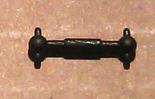
The pilot on the front, as well as having the coupling, also carries the headlight.  The whole assembly, as shown below, is made up from eight parts which includes the main body, handrails, dummy knuckle coupler, front cylinders and headlight, two plastic valve gear bars, clear plastic light corridor and a metal nut used to bolt it onto the locomotive.  The dummy knuckle coupler is not shown (it was missing on this particular locomotive).

Rowa Y6B Pilot Parts

To remove the pilot you will need to first remove the front set pilot wheels.  With the locomotive upside down remove the plastic plug holding in the front wheel set, this usually has a whisker of plastic running passed the wheel set to give it some springiness, again on this particular model it is missing.

Rowa Y6B Pilot Removal 1

The wheel set then simply lifts out.

Rowa Y6B Pilot Removal 2

The newly exsposed screw holds the pilot in place.Rowa Y6B Pilot Removal 3

Once removed the whole assembly will slide off.

Rowa Y6B Pilot Removal 4

The assembly then comes apart very easily into the seven different parts.  Although I have found out that the very early versions had this assembly glued together and are very reluctant to come apart.

Once I had all the parts separated I set about drawing a 3D model of the main pilot section.  My original intention was to make a replacement part that had a socket to receive a Micro-trains Z scale bodymount coupling.  With the 3D model complete and successfully uploaded to Shapeways I ordered one and as usual within about eight days it arrived on my doorstep.  With this first test print it quickly became apparent that I had incorrectly measured the original because as you can see from the image below the steps are smaller than the original on the left. But this is the reason why I test print everything.

Rowa Y6B Pilot First Print

Although the steps were the wrong size I was still able to experiment with the pilot to see how the Z scale coupler fitted.  Although it did fit well I do find the Z scale couplings really tricky to put together and I felt that it looked too small on such a big locomotive.  You may have also noticed that the cow catcher bars run in a different direction, this is because I used the same 3D model parts I have already drawn for my Atlas 2-8-2 replacement pilots.

So taking all that into account it was back to the drawing board, or at least the laptop.  I first fixed the issue with the steps and I also refined a few other details.  Because I wasn’t keen on the Z scale coupling I created a new version with a pocket to accept the N scale Micro-trains body mount coupling and added horizontal cow catcher bars.

Rowa Pilot Coupling 2

The test prints this time came out fantastic, shown below are the two pilots either side of the original. Z Scale coupling on the left and N scale coupling on the right.

Rowa Y6B Pilots New & Old

To reassemble the pilot, first the handrails need to be secured.  The front two pegs clip into the new pilot and the rear tabs fit under the walkways as shown below.

Rowa Y6B N Pilot Assembly 1

Then the cylinders fit onto the main body and the plastic light strip is inserted into the rear of the headlight.

Rowa Y6B N Pilot Assembly 2

The last part to add was the actual coupling.  This slides in from the front and is secured by a screw.  The standard screw which comes with the body mount couplers is too long and would protrude up through the pilot if left as it is, so I cut it short with a pair of side snips. Please use safety goggles if you are going to do this as the ends fly all over the place.  I left about 2mm (0.078″) of the screw protruding from the coupling, the coupling will need to be installed before the screw is fitted.

Next came the actual test fit onto the locomotive and as you can see below it went well.

Rowa Y6B Pilot Test Fit 2 Rowa Y6B Pilot Test Fit 1

The final test was a coupler height check and for this the locomotive is put onto the track and coupled to a Mocro-trains height gauge.

Rowa Y6B Coupler Hight Check 1 Rowa Y6B Coupler Hight Check 2

This same set of checks were also carried out for the pilot with the Z scale coupling and again, as shown below, it all lined up.

Rowa Y6B Coupler Hight Check 4

Rowa Y6B Coupler Hight Check 3

So using the N scale pilot, my preferred coupling, here are two Rowa Y6Bs coupled together.

Rowa Y6B x2 1 Rowa Y6B x2 2

Now I know that the 3D printed pilots work all that is required is a coat of pain.  I used a simple matt black acrylic paint and the finished locomotive looks like this.

Rowa Y6b Finished Pilot N 1 Rowa Y6b Finished Pilot N 2

Normally when I show a new product I also share with you where you can get it but this week I need to do one more final test before I am happy to release the Rowa Y6B replacement pilots, and that is a full running test on a layout with curves and inclines.  This is to check that the Micro-trains bodymount coupler does not interfere with the leading set of wheels as they are very close.  So in a future post I will have some more pictures, maybe some video and I will let you know where you can purchase your own.


Finishing Santa Fe No. 2601 – A Baldwin DT6-6-2000

Over the last two weeks I have been working on my latest release, the Baldwin DT6-6-2000, in this post I wanted to share with you the finished model and how we did it.

Following on from my last post about this model in which I showed you the test print, I needed to make some more minor changes to the 3D computer model.  In particular there were a few concerns about the thickness of the window frames in the cab.  Although the test print had printed successfully, these parts where incredibly thin and posed the possibility that they could get damaged in the shipping and handling process. This has now been improved in the 3D model. Also, and I had to laugh when I did this, the engineers cap had the same problem.  He has now been outfitted in much sturdier attire.

With the model successfully printable and available to all it was time to turn my attention to finishing the test print and making it into a proper model.   For this I once again handed the model over to Bob Norris to paint and decal.

As with all my models which are printed in the FUD (Frosted Ultra Detail) material it needed to be cleaned to remove the waxy residue left over from the print process.  You can read more about doing this in my FAQ section.

Once cleaned, as you can see from the photos below, a lot more of the detail becomes visible.  These photos were taken not long after the model was removed from the Goo Gone, it will turn totally white and opaque in about 24 hours.

DT6-6-2000 Cleaned 1 DT6-6-2000 Cleaned 2

The body shell and truck side frames were then sprayed black all over, the intention was to use decals to get the silver tiger stripe look.

DT6-6-2000 in Black

This is where we had a bit of a shock because the decals we had were not silver but black.  This meant that the areas intended to be striped needed to be painted silver.

DT6-6-2000 With Silver

The silver was brush painted and when dry the decals were applied.

DT6-6-2000 Strip Decal 1 DT6-6-2000 Strip Decal 2

Microscale 60-247 is a set of decals which are silver and will work for this model without the need to paint any silver, you can find them here.

The engineer and cab interior was also hand painted and glued inside the shell.  He is very small but he is visible through the window. A lot of the photographs of these engines show the windows open so one of the verticals has been removed to represent this.

DT6-6-2000 Driver

To add glazing to the unopened windows and doors Bob used Micoscale’s Kristal Klear.  This is a great product which quickly allows you to add small window glazing to models.  Another alternative would be to use small rectangles of clear plastic sheet and glue them to the inside of the shell.  The rear of the doors and windows are recessed to help with this.

With all the decals applied and the shell just about finished it was time to look at lighting the engine.  Because the chassis came from an Atlas C-628 the LEDs on the circuit board are shorter than the shell to allow for the cab.  The light is transferred to the headlights via a clear plastic path, similar to a fiber optic cable.  My 3D printed shells don’t have this clear plastic path.  But the inside of the headlights have a pilot hole ready incase you want to add lights.  This can be done very easily using either the original circuit board for DC (Direct Current) or a drop in decoder for DCC (Digital Command Control).

This particular model will be DCC and the original circuit board has been replaced with a Digitrax decoder, model number DN163A0.  Before the decoder was fitted Bob replaced the LEDs with longer ones as pictured below.  Then he drilled through the headlights in the shell, the LEDs on the decoder line up with the headlights in the shell.

DT6-6-2000 LEDs

Another alternative would be to use the Digitrax sound decoder SDN144A0.  Because the chassis is recessed, as shown on the left of the above photo, there is more than enough room for the speaker and capacitor, although you may need to extend the wires to make it all fit.

Once the main body was painted the handrails were added.  I have supplied handrails with all the shells but they are not attached in their final location.  This gives the modeller the choice of using finer brass wire or an equivalent to getter a smaller rail detail and it also makes it easier to paint the shell.  For this model Bob used the supplied printed handrails.  They come inside the shell on a sprue for protection and need to be cut out, this is a delicate process as they are very fragile and brittle. The sprue also braces the shell throughout the print and cleaning process at the Shapeways factory.   Once the sprue has been removed all 6 handrail sections can be removed and painted.  I have supplied very small dimples or holes in the shell to act as locators for the handrails.  These also act as guides to help if you are adding your own wire handrails.  Bob glued the painted handrails onto the shell, here is what they look like.

DT6-6-2000 WIP 1 DT6-6-2000 WIP 3 DT6-6-2000 WIP 5

To complete the model bob used decals from the Microscale sheet 60-247 to add the numbers and AT&SF road markings, he then sealed the paint and decals with a coat of Testers Dulcote.  The shell was fitted back onto the chassis and here are the results.

DT6-6-2000 Finished 1 DT6-6-2000 Finished 2 DT6-6-2000 Finished 3 DT6-6-2000 Finished 5 DT6-6-2000 Finished 6 DT6-6-2000 Finished 7 DT6-6-2000 Finished 9

These shots were taken on Bob’s DC layout so capturing it with the lights on is not so easy but as you can see from he action shot below, they do work

DT6-6-2000 Finished 4

So there we have AT&SF No. 2601, a Baldwin DT6-6-2000 in N Scale.  You can get your own here or we can provide ‘Ready to Run’ models upon request.  In a later post I will share some videos of this locomotive running, maybe teamed up with AT&SF No. 2602.

A New Drive Shaft For a MDC/Roundhouse/Athearn 2-8-0

A few months ago at the 2014 NMRA(BR) winter meet in Benson, England, I had an unfortunate breakdown with one of my small steam engines.  Upon putting the engine on the track and turning up the power the engine stubbornly stood still even though the motor was spinning frantically.  After inspecting the engine it was obvious that the drive shaft was missing.  So in this post I wanted to share with you how I have fixed it.

The engine in question is an N Scale 2-8-0 steam engine made by Roundhouse (formally Model Die Casting). Sierra 2-8-0 No 28

These are great models and run like sewing machines.  Due to the size there is next to no room inside for big motors and drive parts so Roundhouse installed a small motor in the tender, they even managed to fit in a small brass fly wheel.  The motor connects to the locomotive via a drive shaft which protrudes from the tender into the back of the cab.  The drive shaft then turns a worm gear in the boiler which connects to gears on the axles, consequently driving the wheels.  Because the tender is hinged where it joins onto the back of the engine the drive shaft has to be flexible.  This has been done using a form of ball joint. The balls on the ends of the drive shaft press fit into sockets and are held in place by the springiness of the plastic sockets.  Normally this configuration would simply spin in the sockets but the balls on the end of the drive shaft has two spigots sticking out from each ball.  Each socket has slots corresponding to the spigots so when the drive shaft turns so does the socket while allowing for the movement of the tender.

The drive shaft is made form black plastic and is very small, measuring only 11.25mm long with a diameter of 0.7mm.  So not to be beaten I decided to 3D print a new one.  Luckily I have a another Roundhouse 2-8-0 so I was able to pop out the drive shaft, pictured below, and copy the dimensions. MDC Old Drive Shaft

This was s fairly simple model, the main concern was getting the length and diameters correct.

Roundhouse 2-8-0 Drive Shaft

Then it was off to the printer and a week later I now have a replacement drive shaft.  I printed this in FUD but it should be printable in WS&F or BS&F as well.

After an overnight soak in Goo Gone and a wash off it was ready for a coat of paint.  Pictured below, the drive shaft on the left is the original, the one on the right has been painted.MDC Drive Shafts - New & Old

I first test fitted an unpainted drive shaft, which was successful, then once the paint was dry I fitted the black painted one.  Make sure the pegs in the drive shaft line up with the slots in the socket before you push it in.  It takes a reasonable amount of force to push the ball into the socket and if the pegs are not lined up they will snap off.MDC 2-8-0 No Drive Shaft MDC 2-8-0 White Drive Shaft

MDC 2-8-0 Black Drive Shaft

And there you go, a repaired Roundhouse 2-8-0 with a 3D printed drive shaft.

If you too have been unlucky enough to loose your drive shaft from either a 2-6-0 or 2-8-0 by MRC/Roundhouse or even the newer Athearn ones you can get a replacement here.  I also do a set of two, just in-case you need a spare which you can get here.


*News* – Shapeways Normal Service Has Resumed

The issue with the Shapeways site has been resolved and the models are back up in my shop. Shapeways have rectified the problem with their search facility which was causing the problem and you should be able to shop now without any further issues, but please email me at jamestrainparts@yahoo.co.uk if you are still experiencing difficulties. Thank you for your patience.

*News* – Shapeways Experiencing Technical Difficulties

I know it is not my usual posting night but I wanted to let you all know that Shapeways are currently experiencing some technical difficulties with their website.  Not all of my models are currently visible and some models are not able to be ordered at present.  Shapeways are doing all they can to resolve this issue as soon as possible. Apologies for the inconvenience, and I’ll post again as soon as the issue has been resolved.

A Baldwin DT6-6-2000 Center Cab In N Scale

Over the last few weeks I have been drawing and designing a kit to make an N scale DT6-6-2000 using an Atlas C-628 or C-630 powered chassis. The test print has now been made and in this post I will share with you the results, the small changes I have made and where you can buy your own.

You can read more about the design in Part 1, Part 2 and Part 3 of the drawing process.

Straight out of the Shapeways box the DT6-6-2000 shell looked great.  Even though it was covered in the normal waxy residue I could already see most of the detail, and nothing seemed to be damaged, badly printed or missing.  To get the model ready for initial photos I simply washed the parts in warm soapy water. This still leaves a waxy residue on the parts and they can’t be painted yet, but as you can see from the pictures below it is enough to show you what  it looks like.

DT6-6-2000 Test Print 1

Even though the parts haven’t been properly cleaned yet I couldn’t resist trying them out! First I looked at the truck side frames, and they fitted perfectly.  All the little clips and catches on the Atlas power truck lined up with the printed side frame and it fitted together with a positive click. Below is a comparison showing the Atlas truck side frame on the left and the printed one clipped onto the power truck on the right.

DT6-6-2000 Test Print 9

From the under side you can see the clips and catches as well as the gear holes.

DT6-6-2000 Test Print 10

Having gone this far I had to try them both in the chassis and do a test run.

DT6-6-2000 Test Print 11

The chassis ran perfectly proving the side frames where not too tight on the axle ends and there wasn’t a clearance issue between the underside of the printed side frames and the rail tops etc.

The detail on the actual shell is very crisp as you can see from the photos below showing the exhaust stack, lifting lugs and horns.

DT6-6-2000 Test Print 8 DT6-6-2000 Test Print 4

Even the uncoupling bar that runs across the top of the knuckle coupler has printed perfectly although it is very hard to see in the image below.  When the FUD material is freshly printed and transparent like this it is very difficult to photograph and being wet with waxy residue doesn’t help!

DT6-6-2000 Test Print 7

Next I wanted to test fit the shell on to the chassis but to do that I needed to remove the handrails from inside the shell. As with my EMD DD35 kit I have printed the handrails fixed to the inside of the shell. This is firstly to protect them and secondly to avoid adding expensive material to the model in the form of a sprue.  The handrails are mounted on cross braces that also hold the shell square as you can see below.  Sometimes when a print run is finished the parts cool a little bit too quickly and thus can cause a little bit of distortion, so the braces help prevent that.  If you get a printed model which has distorted you can read about how to fix it here.

DT6-6-2000 Test Print 17

I cut the handrails out using an X-Acto knife but I’d made the ends of the cross braces a little too big which made them hard to cut. I ended up pushing very hard which is not recommended with FUD as it can be a brittle. I have since reduced the ends of the cross braces which will make the hand rails much easier to cut out.  All six hand rails come out in one piece as you can see below.

DT6-6-2000 Test Print 6

The shell was now ready to fit onto the chassis and it slid over the metal frame and located onto the metal lugs with ease.  As one end of the chassis is higher than the other I added locating brackets inside the shell to sit on top of the chassis at the relevant heights; this means the shell will only fit on one way.  In the photo below you can see the lower end is on the left.

DT6-6-2000 Test Print 12

With the shell test fitted the first thing I noticed was the trucks seemed very close to the triangular section next to the front steps.  I was worried that this would prevent the trucks from turning but after doing several tests around a tight corner on my layout I discovered it was not close enough to touch but as a good measure I have moved the triangle away from the truck a little bit more.  The locomotive trundled around my small yard quite happily as you can see below.

DT6-6-2000 Test Print 13

The last big check I wanted to make was the coupling pockets.  The shell has been designed to receive Micro-Trains N scale body mount couplings in a pocket on the underside.  There is a pilot hole ready for the mounting screw and a gap in the pilot to allow the coupling to poke through.  As the pilot hole was full of wax residue, and slightly smaller than the screw diameter by design I drilled out the hole using a #62 tap drill from Micro-trains and taped it using the 00-90 tap from the same tool set.  Once I had assembled the Micro-trains body mount coupler I pushed the screw through the coupler.  The standard screw that comes with the body mount couplers is two long for the shell, it would protrude up through the walkway if left as it is, so I cut it short with a pair of side snips. Please use safety goggles if you are going to do this as the ends fly all over the place.  I left about 2mm (0.078″) of the screw protruding from the coupling and inserted it into the pocket. The screw lined up perfectly with the hole and I was able to do them up.  As FUD is a plastic, don’t over tighten the screw or it will pull out and ruin the thread in the shell. Also if it’s too tight it will prevent the coupler from working properly.  Once both were installed I was able to check their heights and see if they functioned correctly.  I did this using a Micro-Trains N scale coupler height gauge as pictured below.

DT6-6-2000 Test Print 15

The high was perfect.

DT6-6-2000 Test Print 16

And finally, as you may recall, I also included an engineer for the cab. and here he is.

DT6-6-2000 Test Print 2

He is very small, and this photo doesn’t do him justice.  The only issue I had was not with him but with my design.  I found that even though I had put locating locating lugs in the shell to fix him in the right place it would be very difficut to do as there is nothing to get hold of him by.  So I have now added a tab on the underside so you can grab him with a pair of tweezers.

Now all the checks and tests are complete I’m happy to make the kit available to buy in several options such as unpowered dummies and with or without truck side frames.  You can find them all on the new website page here.

In a future post I will share how my DT6-6-2000 looks painted up in Santa Fe colors transferring freight from one yard to another.