Specialist Brick Feature for an S&D Signal Box – Part 2

In December last year I shared with you my designs for some special 3D printed brick feature details for a OO Somerset & Dorset Railway Signal Box at Bournemouth West Station; you can find the post here. In this post I’ll share with you how they came out.

This brick features, which I mislabeled as a ‘brick castellated feature’ last time, is called ‘dentil’ brickwork from the Latin ‘dens’ meaning ‘tooth’.  It’s a simple form of corbelling.  I printed the parts in strips on a sprue in Shapeway’s White Strong & Flexible material, as you can see below.

sd-dentil-brick-work-1

The actual construction of the signal box hasn’t started yet but the modeller, Steve Knight, has made a mock-up to see if the parts will work.

sd-dentil-brick-work-2

The wall has been made from layered card with the brick finish plastic card on top.  The top dentil and bottom sloping brick sections are simply glued in place.

sd-dentil-brick-work-3 sd-dentil-brick-work-4

The whole section is then painted brick red.

sd-dentil-brick-work-5 sd-dentil-brick-work-6 sd-dentil-brick-work-7

The brick details really stand out and, once weathered, will look wonderful.  As I said at the start this is only a mock-up for the signal box, but the image below gives the idea of how it’ll look on the layout.  All the track work and details, like point rodding, have already been finished.

sd-dentil-brick-work-8

Once Steve has completed the box I’ll share the result with you.

This weekend is the Bournemouth N-Trak Convention which I’ll be attending, hopefully on both days.  You can see videos and photos from a previous visit in 2014 here. I intend to take lots of photos and video this time as well so I can give you a nice full post next week for those who can’t make it.

Changing Sounds on Digitrax Sound Decoder – Part 2

In last week’s post I shared with you a simple method of changing generic sounds on a Digitrax sound decoder and how to adjust effects like volumes.  You can find the post here.  This week I’m going to show you step by step how to completely change the sounds so you can make them match the locomotive you’ve installed your chip into.

To do this you will need an extra bit of DCC equipment supplied by Digitax; their PR3 or PR3EXTRA as pictured below.

pr3extra
This device is designed to connect your computer to your layout to allow computer control or to simply allow you to communicate with your other Digitrax DCC products via their LocoNet system.  It can also be used, along with your computer, as a stand alone programmer and that’s what we’re going to do.

Depending on what computer you have and what operating system you’re using, your PR3 may need to have a driver installed, which can be downloaded from the Digitrax site here.  Once installed the PR3 is connected to the computer with a USB lead and requires its own power supply, which comes with the PR3.  There’s a small twin screw terminal block on the front of the PR3 which is where you connect wires for your programming track.  As I’m often doing this at shows I simply have a strip of track with two wires soldered to the end.

The next step is to download and install the software to your computer.  Again this is supplied by Digitrax and is called Soundloader and can be downloaded here.

The current version, at time of writing, is v2.2.  When you first open the software you get a window that looks like this.

soundloader-start

At the bottom of the screen it says ‘Could Not Open COM Port’.  This is because it doesn’t know how your PR3 is connected. At the top of the screen on the drop down menu is ‘COM Port’.  Select this and it will open a window with a drop down menu.  Providing your PR3 in installed and plugged in it will list the com port which you can select.  Then the screen should look like this.

soundloader-1

The software is now ready to use.  When you place a locomotive on the programming track the software will automatically pick up the DCC decoder and interrogate it, as you can see below.  The software is finding out what sort of decoder it is; this is important as different decoders are capable of different things.

soundloader-2

Once complete the software will display the information in the bottom left of the screen.  This decoder is a 16bit Series 6.  It also tells me the size of the flash. This is the amount of flash memory, just like a flash drive or SD card you use to store photos in a camera.

soundloader-3

The next step is to get your sounds or sound project for your locomotive.  There are a few places where you can get them from but the main place is Digitrax’s website here.  Sound Projects or SPJ files are not official files, that is to say they are not produced by Digitrax, rather they are created by the Digitrax user community and shared though the site.  Another place to get sound files and support is the Digitraxsound Yahoo Group.  This is a great site to ask advice and help solve any issues.

Once you have downloaded the file you want you can load it into the software by selecting file and open.  The screen will then look similar to this.

soundloader-4

The big green button tells us that it’s ready to download the Sound Project to the decoder.  If this button is not green then there’s an issue. This could be because the SPJ file is for a different decoder or there’s not enough room on the decoder for your file.  For this example you can see the ‘Flash Download size’ is 341248 Bytes and the ‘Decoder Free Flash’ size is 1769472 Bytes, so we have plenty of room. By pushing the green button three things will happen.  First, the software will erase the current flash on the decoder; normally the speaker makes a squealing sound when this happens, so don’t panic.  Second, the software will download the SDF files; these are the command files which tell the decoder what the sounds are.  And third, it will download the Wav files; these are the actual sound bytes and this process takes the longest.  Below you can see a screen shot of this happening.

soundloader-5

Once complete, that’s it.  If you put the loco on the tracks it should play the new sounds.  However there are a few traps which you can fall into which may prevent it from working, so I like to use the Sound Test tool first.  This can found on the drop down menu and when opened looks like this.

soundloader-6

In the image above the Sound Test tool is still reading the decoder.  Once complete you should be able to push the relevant buttons and the sound decoder will respond.  Another nice feature is you can engage the forward and backward motion to hear the steam chuffs or engine sounds, but the loco won’t actually move.  In the screen shot below you can see I’m testing the forward motion with F4 & F7 switched on.

soundloader-7

If however you find you get to this stage and you still don’t getting any sounds there are a few things to check. In last week’s post we discussed CV60 which changes between the different sound sets.  If, for example, you had previously set the decoder to set 3 and then flashed in a new SPJ file, set 3 will be empty as the new SPJ will load into set 0.

If this still doesn’t work it may be a problem with the SPJ file.  I had a similar problem to this recently and was able to get the help from the Yahoo Group.  If an SPJ line within the file is not assigned it can cause issues.

Looking again at the screen shot below you can see one of the sounds, 006 DEISEL_RUN_HI, is not assigned.  By right clicking on this you can select ‘Restore Association’.  If it had previously been assigned it will correct itself.  However, if nothing changes right-click again and select ‘Assign Silence’.  This will make it associate with a Mute file.

soundloader-4

Once the SPJ file has been updated it can be re-flashed onto the decoder and this time all the sounds should play.

As I mentioned before the PR3 can be used to communicate with other devices via the LocoNet system and this is something I will share with you in a later post.

Changing Sounds on Digitrax Sound Decoder – Part 1

In October last year I showed you how I fitted a Digitrax DCC sound decoder and speaker into the tender of an N scale steam locomotive, you can read the post here.  At the end of the post I mentioned that when the locomotive was put on the track and powered up, diesel sounds played instead of steam.  In this post I’ll show you how this can be changed.

As standard, Digitrax sound decoders come with pre-installed sounds, normally for generic diesel and steam locomotives.  These are also for US outline locomotives so they may not be ideal if you model trains from other countries, but as a generic they’re not too bad.

There’s a simple way to change the generic sounds and adjust the volumes. And there is a slightly more complex method which allows you to totally change the sounds, which then enables you to use them for other countries too.

The first and simplest method is to switch between the diesel and steam sounds and, for many, this is sufficient.  This is done by altering the value of a certain Configuration Variable or CV.  CVs are the electronic switches within the DCC decoder which control all the options such as the locomotive’s address, light functions, maximum speed and sounds.  The majority of DCC controllers or command stations have the ability to read and changes these CVs.

I won’t be able to give you instructions on how to change the CVs on your particular DCC controller as there are so many different makes and models, and they’re all a bit different. However you should be able to find out how to do it from your operator’s manual; it’s normally under the decoder programming section.  The good thing is the principle is basically the same for all.

Normally this involves placing your locomotive onto a programming track.  This is a section of track which is totally isolated from the rest of the layout and only connected to the programming track output on your DCC controller or command station.  Why do this?  Well, if you programmed through the main track feed it will talk to all of your trains at the same time. Also the programming track has a much lower power output, so if something is wrong it shouldn’t damage the decoder.  There are ways to program specific locomotives on the layout by ‘programing on the main’ but I’ll discuss that at a later date.

With your locomotive on your programing track, ask your DCC controller to read CV60.  This is the switch which tells the sound processor which sound set to use. If CV60 = 0 then it will use the steam set, if CV60 = 1 then it will use the diesel set.

So if you’ve installed the sound decoder in a steam locomotive and CV60 = 1, follow the instructions for you DCC controller to write or change CV60 to 0.  Then, when you put the locomotive on to the main track, it will play the steam sound set.

Using this basic method of altering CVs you can also alter other sound related functions. CV58, for example, is the master volume.  As standard it’s set to 9 but can be increased to 15 if required.

Below is an extract from a Digitrax Sound Decoder manual showing some of the CVs which can be adjusted.  I would recommend being methodical when doing this as changing the wrong CV can cause the decoder to behave in a strange way. In the event that it all goes wrong and you don’t know what you did, don’t panic!  There is a simple way to reset the decoder back to factory settings.  This is done by setting CV8 to 8.  Please note that not only will this reset volumes and sounds to the diesel set but it will also reset your locomotive number to 03.  This is is definitely something only for the programming track.

typical-decoder-digitrax-cv-settings

I like to increase the master volume as well as the whistle and prime mover/steam chuff sounds but leave the bell turned down.  I find the bell a bit annoying!

One thing to consider, if you set the volumes so they’re just right for you at home, where it’s probably fairly quiet, you may find if you take your trains to exhibitions or club nights the sounds may get drowned out by the background noise.

But what if you don’t want your locomotive to sound like a generic US steam engine; what if it’s a British LNER A4 or German Ice HST?  Well, that can be changed too using the slightly more complex method I spoke about earlier and in next week’s post I will show how to do it, step by step.

Adding Draw Bars to Yosemite Valley Railroad Log Cars

Back in 2013 I started drawing my Yosemite Valley Railroad log cars; you can read the original post here.  Since then I’ve built up a nice train of cars, however, I haven’t added couplings to them all.  So in this post I’ll share with you my simple and cheap design to complete the cars.

The original log car design, as pictured below, was intended to be used with Micro-Trains Z scale couplings.  These are compatible with N Scale couplings but are much smaller and look more prototypical.  However, they are very fiddly to assemble and, if you are doing lots of cars, can get rather expensive.  Also, if the coupling is slightly out of vertical alignment it can uncouple when the cars cross any bumps in the track.  As I only run my log cars in a fixed rake and don’t do any switching with them, installing the Z scale couplings on all the cars seemed a bit over the top.

Yosemite Bulk Head Log Car 2

To resolve this I have designed a draw bar to be used with the same mounting point. The Micro-Trains coupling box fixes to the cars with a screw; a pilot hole is printed in the underside of the car chassis to ensure the couplings are fitted in the right place.  My draw bars, as pictured below, are simply dogbone-shaped strips of 3D Printed Nylon.  This material is Shapeways’ White Strong & Flexible and I’ve used this as it’s both strong and cheap to produce.

yosemite-log-car-drawbars-1

Pictured below you can see the draw bars next to the log cars for a size comparison.

yosemite-log-car-drawbars-2

The draw bars will come in sets of eight on a sprue and can simply be twisted or cut off with a craft knife.

yosemite-log-car-drawbars-3

The holes in each end are the right size for a Micro-Trains screw, although you will need to shorten the screw and tap the hole in the car body.  Micro-Trains supply a tap set for this purpose which can be found on their website.  Alternatively I use tiny screws which are just about the right length.  I tend to get these from old CD drives and computer components which I’ve taken apart before throwing out. You will be amazed how many tiny screws you can accumulate like this.

Below you can see one of these screws in the draw bar, as it has a point it will tap the hole as you screw it in.

yosemite-log-car-drawbars-4

When the draw bar is fitted to the car the screw doesn’t want to be tight otherwise it won’t allow the draw bar to rotate.  I have fitted the draw bar under the bulk head end of the car, that way if the screw is too long then the excess length will poke up between the bulk head braces and will be hard to see.

yosemite-log-car-drawbars-5

The screw does need to be tight enough so when the car is on the rails the draw bar doesn’t drop as you can see below.

yosemite-log-car-drawbars-6

For the other end you could use another screw but this means the cars are permanently coupled together.  If you do a lot of exhibitions, like me, then this isn’t very practical.  So I use a short section of wire simply glued into the existing hole.  It needs to be a stiff, solid core wire, not a multi-strand.  This also means all the cars can only be coupled together facing the same way, just like the originals.

yosemite-log-car-drawbars-7

This wire then acts as a pin which will fit nicely into the hole in the end of the draw bar to couple the cars.

yosemite-log-car-drawbars-8

Lots of cars can be assembled in this way but the first and last car will still need a regular coupling on one end so locomotives and cabooses can be attached.

yosemite-log-car-drawbars-9

My test pieces have been printed in white simply because it’s the cheapest colour but these will be available in black as well.

I’m going to assemble a few more cars and run the set at my local club as a test before I release the draw bars for sale.  Logically there’s no reason why these couldn’t be used on any freight cars which have a body mounted coupling so I’ll try that as well and let you know how it works out.

Drawing a Dummy Chassis & Trucks for an N Scale EMD SD50 Part 3

Recently I shared with you my designs for a dummy chassis.  It was designed to be used with an Atlas N Scale SD50 shell, as shown below, and you can read the post here.  In this post I’ll show you the outcome and where you can get one.

emd-sd50-dummy-chassis-mk2-6

As I mentioned in that post, and as you can see below, the fuel tank was a little bit low.  This has been corrected in the 3D model, raising the tank connection points on the chassis and adding a tiny bit of height to the truck towers.

emd-sd50-dummy-chassis-mk2-7With the fuel tank and trucks painted in acrylic ‘locomotive black’, the loco looks the part and spent some time last weekend running around our club layout behind other locomotives.

ns-emd-sd50-dummy-chassis-2

This dummy chassis kit will also fit an Altas’ SD60 and SD60M shell as all three locomotives use exactly the same chassis.  The kit is available in both Shapeways’ Frosted Ultra Detail and Frosted Extreme Detail materials and can be found here.

If you want to use the original light board with the chassis this can easily be done with my ‘Dummy Chassis Circuit Board Mount’ as shown below.  The actual mount is printed in Shapeways’ White or Black Strong and Flexible material and can be found here.

emd-sd50-dummy-chassis-circuit-board-mount

In order to add power to the circuit board, power pickups need to be added to the trucks.  This is done in exactly the same way as with my C-628/C-630 dummy chassis trucks and will look similar to the example below. You can read how to do it in this post.

IMAG0603

Each truck will need three Fox Valley 36″ metal wheel sets (FVM3611), which are not included in the kit. If you don’t want power pickup then Micro-Trains 36″ plastic wheel sets will also fit but I recommend the metal ones as they add weight to the trucks.  The trucks on their own are very light and more weight helps them run smoothly.

The trucks are HT-C type trucks which EMD used from 1970 to 1994 on their three axle  trucked locomotives, the noticeable feature is the center shock absorber on each side.

emd-sd50-dummy-chassis-3

As these trucks have been used for such a large range of locomotives I have also made them available on their own.The kit consists of two HT-C trucks and two bolster pins. These can be found here.

Next week I’ll have some more 3D printed products to share with you.

Drawing a Dummy Chassis & Trucks for an N Scale Alco C-855 Part 2

As hinted at in last week’s post I’ve been working on the dummy chassis for the Alco C-855 and C-855B.  This week I’m going to share some of the progress with you.  You can read the first part here.

The actual chassis for the locomotive is a simple shape and as it fits inside the shell there’s no detail to add, with the exception of the air tank behind the fuel tank.  However, as this is normally hard to see I’m happy to 3D print the whole chassis in Shapeways’ White Strong & Flexible material.  This is a real bonus as, given the size of the chassis, it would be expensive in their Frosted Ultra Detail or Frosted Extreme Detail materials.  The WS&F is still very accurate which means the truck bolster pin holes will be in the right place as will the shell locating positions.

The trucks are very visible and in order to show as much detail as possible these have been designed to be 3D printed in the FUD or FXD which is currently the best quality 3D print material they offer.

In the last post about these trucks I showed you the first few steps which led to the basic truck and bolster pin connection being designed, as you can see in the image below.

alco-c-855-dummy-truck-2

Since then I have developed the span bolster connection between the two trucks.  Unlike the prototype, which had a solid bar connection from coupling to coupling, the model uses a bolster pin to connect the lead truck to the chassis and the second truck simply floats between the first truck and the fuel tank.  The powered chassis trucks, shown below, are made of several parts which screw together forming a permanent connection, which can swivel side to side and has some up and down movement.

cpn-cor-u50-trucks

3D printing has the advantage of being able to produce the two trucks as one piece while keeping the movement between them.  Below is a section taken through the trucks in which you can see their connection.  The truck on the left has a lug on the back with a slotted hole in the end.  The truck on the right has a slot in the cross member which the lug passes through.  It also has a pin which passes through the hole in the lug preventing the trucks from separating.  The two trucks are inseparable and to make this as one piece in any other way would be impossible.

alco-c-855-dummy-truck-3

Below is render of the front pair of trucks.

alco-c-855-dummy-truck-4The second truck has no bolster pin connection on top but I’ve left a level area to add a weight if required. The weight may be required if the truck lifts or bounces as the loco crosses turnouts.

At the rear of the second truck is a tail which fits into the gap in the chassis fuel tank.  When the trucks are fitted to the chassis with the bolster pin the tail will stop the trucks from rotating out, but will still allow the trucks to swing enough on corners.

At the front of the trucks is the coupling connection.  As with my other models I’ve added a pocket to accept a Micro-Trains body mount coupler.  The pocket is upside-down so the coupler drops in from the top and is fixed with the standard small screw.   This was done to maintain the strength of the pocket without adding extra material; if the coupling was fitted from below the coupling areas would be very bulky which is expensive and wouldn’t look right.  On either side of the coupling pocket I’ve added the walkway texture which forms part of the access steps to the front of the locomotive.  The rear set of trucks, as pictured below, doesn’t have this detail, nor does it have such a big pilot. The pilot is the area around the coupling.

alco-c-855-dummy-truck-5

The C-855B dummy chassis will have the rear set of trucks at each end as there aren’t any access steps at the ends of the B Unit.

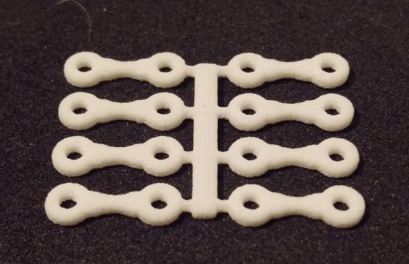
With the designs complete the C-855 dummy chassis and trucks were sent to print and arrived looking very nice.

alco-c855-dummy-chassis-test-print

The chassis section, as it’s printed in WS&F, was ready to use right away, but the trucks needed their normal cleaning to remove the waxy residue left over from the print process.

The chassis was a prefect fit inside the shell.  With the powered chassis I designed a replacement fuel tank which fitted to the underside of the metal chassis as shown below.

Alco C-855 Fuel Tank Fitting 2 (render)

This fuel tank section had holes in the sides to locate the shell lugs.  The dummy chassis has these same holes so the shell clips on and can only be removed by spreading the shell.

The holes for the bolster pins had a bit of surplus material in them so I reamed them out with a drill bit which was roughly the same size as the hole.  Then I was able to fit the two sets of trucks, making sure the correct truck was at the front and the tails were in the fuel tank slots.

The Fox Valley wheel sets dropped in nicely to the trucks and then the dummy chassis was ready for some testing.

alco-c-855-dummy-loco-1

A UP heritage unit had the pleasure of pushing the dummy C-855 around our ‘Solent Summit’ layout this weekend at a running meet and it went very well.

I had put some weight inside the fuel tank area, as you can see below, and with the added weight of the metal wheels the dummy chassis tracked very well across turnouts and through bends.  I will probably add a bit more so when the weight of a large train is behind the locomotive it won’t try and roll as the train runs around corners.

alco-c-855-dummy-chassis-3

I am going to make a slight change to the spacing of the trucks by changing the length of the connecting lug so it perfectly matches the Con-Cor trucks used on the power chassis; currently they are spaced slightly closer together and I may add a little bit more depth to the truck frames just so they look exactly the same.

The next thing for me to check is the coupling fitting and height which I will be doing next week but for now I aam very happy with the C-855 Dummy Chassis.

alco-c-855-dummy-loco-2

The design for this chassis, once complete, can easily be tweaked to fit the Con Cor U50 and Gas Turbine chassis and I’ll be sharing that with you soon.