This week’s post will be a continuation of my step-by-step build of an N Scale A-B-A Ready-To-Run set of Alco C-855 locomotives. And this post will be concentrating on assembling the chassis. You can find part one of the build here.
Now the chassis sections have been extended it’s time to reassemble all the parts. And for this build I’m also going to upgrade all the motors to newer Kato drives. In the picture below you can see all the original parts plus the new Kato motor in the top left-hand side.

For this post I’m going to assemble the second chassis which you may remember from last week is for the B unit but the process is exactly the same for all three locos. To start with I add the black plastic isolators into the pockets on the underside of the lower chassis section followed by the metal truck fixing. Both are held in place by a countersunk screw, the shortest ones, which only pass through the lower chassis section.

Next, and this in an important one not to miss, the first new 3D printed part needs to be added. It’s the small square screw fixing which holds on the fuel tank. In the original the lower chassis has a threaded hole to receive the screw but as this section has been replaced by the stainless steel chassis extender a new fixing is required. Threading the hole would require more work and it’s much easier to drop in this plastic part.
 The square part simply presses into the square hole.

It will stay in place by friction and once the motor is fitted it can’t fall out.

The motor sits in a plastic cradle; this is to isolate it from the metal chassis.

The cradle has a peg on the bottom which fits into the hole in the chassis to ensure it’s in the right way around.

Next comes the motor. Although I’ll cover this here I’ve written about this procedure before in a bit more depth which you can find here. The new Kato motor doesn’t come with any gears on the drive shafts so the original ones will need to be removed from the old motor.

This is actually fairly easy to do. I use a pair of needle nose tweezers, simply grip the shaft behind the gear and push it off. Just don’t do it too fast or the gear will ping off behind the work bench!

To fit the gears to the new motor simply press them on with your fingers. They want to go on so far that the shaft pokes out the other side but make sure the gears are not tight to the motor body and the motor can spin freely.

The next 3D printed parts are the drive shaft extenders. These are toothed parts which fit inside the existing cup gears making them longer.

I used to glue these in but as my fellow modeller Mike Musick pointed out, they work better when left free with a bit of movement. You can read Mike’s views on this here.

Also, as you may remember from last week’s post, Con Cor have over the years made a few changes to their chassis and one of those changes was to this cup gear. The very first design had a different number of teeth in the cup. This means the extender won’t fit. But don’t panic, firstly these early chassis are now getting rather rare but if you are using one for you C-855 build you can get drive shaft extenders which will fit here.
The motor is now ready to be added into the chassis. But first it’s very important to make sure the new drive shafts spin freely without any rubbing on the chassis. Across all the Con Cor chassis I’ve converted I’ve noticed that the drive shaft length varies; I have no idea why. I’ve supplied the drive shaft extender for the more common shorter lengths I’ve come across. This does mean that if you have longer ones the drive shaft will now bind against the chassis extender. To overcome this pop the drive shaft back out and file down the 3D printed part on the cup side. Running the part up and down a file will do this. But be sure to make the reduction even. I would also recommend doing a bit at a time and test fitting as you go as you don’t want to make them too short. If you do you can get more here. Once everything is good this would be a good time to add a tiny amount of light oil to each bearing, just a drop.

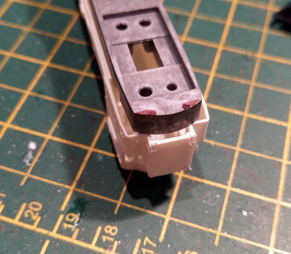
There may also be one more issue to resolve if you’re using the latest Rail Barron version of the chassis. Con Cor updated the motor casing and added the curved notches you can see in the picture below. And therefore added some material into the motor cradle so it’s a nice tight fit. But this means the Kato motor won’t fit! It fits fine in all the others.

These extra plastic parts need to be removed to get the new Kato motor in and I find the best way to do it is with a with a small burr bit in a Dremmel style tool.

All four corners will need to be removed to allow the new motor to fit.

Also, and this apples to all the cradles, a shim needs to be added to the base of the cradle as the new Kato motor is slightly shorter than the Con Cor one. Before you glue the shim in a test fit is required because if it’s too thick it will create uplift on the cup gears which will be noisy and wear out the motor.

The motor fits in to the cradle with the motor contacts at the end with the larger hole.

You’ll need to lift the drive shafts in order to fit the motor in.
Once fitted and you’re happy that everything spins freely, and the motor turns both drive shafts, it’s time to add the rest of the chassis. There are two plastic separators which also hold down the drive shafts, these get fitted next.

Then the top section of the chassis can be fitted and the other screws fitted between the top section and the metal truck fixing. The longest screws with a plastic insulator are used on the right hand side. The medium screws are used on the left without insulators.

With the trucks installed the extended chassis should look like this.

At this point, using wires from a DC controller, I do a basic test to make sure everything runs well. If it’s noisy, won’t run, or sounds like it’s struggling, STOP, there are a few things to check.
- Can you easily turn the motor with your finger?
- Are the drive shafts seated properly?
- Check the drive shafts are not too long and binding on the chassis.
- Check the gears on the motor have been pushed on far enough but not too far.
- Is the shim under the motor too thick forcing the gears up into the cup gears?
- Are the gear towers in the trucks jammed?
Hopefully everything runs okay with all the checks done and any issues corrected.
The next step is to wire up the chassis, I will be doing this for DCC but I’ll cover DC as well and it will all be in the next post on this project.


 Next week I’ll have some real steam to share with you as I spent a day at ‘The Great Dorset Steam Fair 2018’.
 This did help and made it much easier to reinstall the rivet. But the issue of re-flaring the rivet was still a problem and I was finding it hard to do as I couldn’t get a supply of new rivets. This lead me to start cutting part of the loop away to leave a ‘C’ shape which could be forced over the rivet. As it is a ‘C’ shape it would not fall back off the rivet and the rivet didn’t need to be un-flared in the first place. The original peg, what was left of it, could be cut away and the new one could simply be clipped in.
 Then in June 2017 when Shapeways restructured their pricing system this model became rather expensive as each individual part had an additional $1 handling charge added to the cost. But the answer is my new Mk4 version of the crank pin which you can see below.
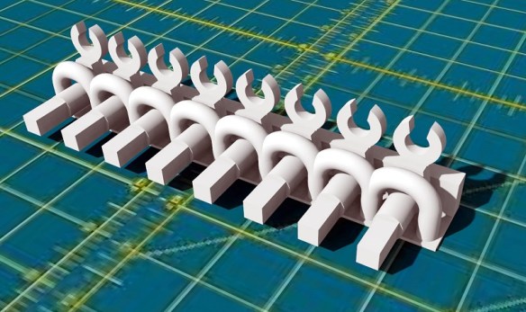


 The gray wire is the bottom motor feed and runs outside the chassis and is soldered onto the bottom motor tab.


You must be logged in to post a comment.