Replica Railways/Bachmann OO Locomotive Split Axle Repair

In January of 2019, I shared with you my design for a 3D printed axle set to fix Mainline steam locomotives with the large drive gear on the center axle.  You can find the post here.

The manufacturer Mainline was incorporated into the Bachmann company and several of the designs stayed the same.  These are what I call the large center gear models, and have the square shafts on the wheels, such as this modified Hall locomotive below.

But another popular brand which Bachmann also incorporated was Replica Railways.  These locomotives, such as the LNER B1 below, have a similar design to the Mainline locomotives in that they are a split chassis design without wires, but the main difference is the motor and the power transmission to the wheels.

These have a totally different motor that drives the rear axle via a smaller gear than the Mainline locos.  The side rods then drive the forward wheelsets which have ungeared axles.

Along with the rear gear being smaller, so are the axles, and sadly the wheels do not have square shafts.  This causes the wheels to get out of quarter when the axles split and everything jams up.  These are also made from the same material as the Mainline ones and it’s very common for them to crack and split.

This particular model had at some point been repaired in the past and the standard method for this was to glue the damaged axle in place. This means when the axle finally breaks down completely there is glue in the wheel which prevents a new axle being fitted.  In the photo below you can see the pocket around the center stub is full of glue.

To get this out I drill several holes in the glue until it starts to break up and can be pulled out with tweezers.  This also depends on the type of glue that was used.

Below you can see the holes I started drilling in the glue.  Make sure you don’t go too deep and start drilling into the wheel. The way to check is to look at the swarf coming out.  This particular glue was fairly transparent so as soon as a fleck of silver came out I knew I was as the bottom of the pocket.

Once all the glue is removed you should have something which looks like this.  The rear axle, which has the geared axle, usually has traction tires.  The center wheels have a larger connection for the side rods as this is also where the piston rod and eccentric rod attach.

The three axles have been drawn up and printed in my usual material, Shapeways Smooth Fine Detail Plastic.  I’ve put them on a sprew, which doesn’t actually touch the parts, for ease of printing.

Because these axles have round holes it means unless the wheel is a good fit it can easily rotate inside the axle, but if it’s too tight the wheel will split the new axle, just like the original.  Because the Mainline axles have square holes this is less of an issue.  I’ve purposely drawn the hole in the axles ever so slightly smaller than the wheel center stub.  I use a drill to carefully ream out the hole because, as I have shown in other posts, there will always be 3D print residue in the hole and it needs to be a perfect fit.

The axle can then be pressed onto the wheel; it needs to go all the way into the pocket.

The corresponding wheel can also be fitted but at this stage, it’s vital to get the quartering right.  This means one wheel needs to be rotated 45° to the other.  Each wheelset must be set in the same configuration.

All three wheelsets can then be replaced in the chassis.

Often at this point is I get asked which way round all the rods connect, so I’ll run through the sequence.  Below you can see the simple side rod connects the center wheel to the front wheel.  The joining side rod, shaped to represent a side rod joint, connects the rear wheel to the center.

The joining side rod is connected first, hooking over the connecting peg.

Second is the simple side rod sitting on top of the joining side rod.

Third is the spacer, with the grooved side facing up.

Fourth is the piston rod, which fits over the spacer.

And lastly, the eccentric rod fixes into the wheel with the special screw which holds it all together.

Testing the loco is always, hopefully, a happy moment and I like to test motion before the loco is put on the track.  Below is a video of the first test.  The slow speed is a little lumpy partly due to the motor but this went away once it had done a few laps of a test track.

Because the hole in the axles needs to be such a good fit and I’ve come across some variations in the size of the wheel pegs, I’ve provided a spare axle with the set so you can use this to check and see if it fits or whether it needs enlarging.

The axle and gear set can be found here.

Despite being harder to install than the Mainline kit, mainly due to the quartering issue, these do work well as a repair and I’ve fixed many damaged Replica Railways locomotives which, without the part, would be redundant.

I have some more 3D printed gears in my latest test print and once I’ve installed and tested those I’ll share them with you as well.

A Baldwin DT6-6-2000 in HO – Trucks Part 6

Last Friday I had a delivery from Shapeways containing the new truck centers and gears for the HO Baldwin DT6-6-2000 project.  They look good, and although there were a few issues, I thought I would share with you how they came out and what was wrong, rather than order some more and just show you the finished item.

I usually order several parts for different projects at the same time, with some of them combined on a sprew.  Below you can see the truck center frames and lots of parts including the four new gears; they are located to the left of the sprew.

The four new gears are small and I didn’t want any parts of the sprew to touch them as it would need to be cut off, leaving a rough surface.  So I surrounded them in a cage, which worked well.

The gears were free to move about, but couldn’t fall out.

Close up, the new gear is a good match for the original; the new gear is still covered in 3D print residue, which is why it looks a bit fuzzy.

The truck centers came out very well and appeared to be a direct replica of the original, with the desired changes.

The first problem came when I started fitting the gears into the holes.   Each gear has a shoulder and an axel on each side.  The axel fits into the hole and the shoulder acts as a spacer to position the gear in the center of the frame.

But in the 3D model, I’d forgotten to make the shoulder part of the gear, so it was 3D printed as a separate part which just happened to be close enough that the support material held it in place.

The axel and shoulder simply come off and you can see all the support material in the middle of the gear.  The same thing happens on both sides so you end up with a flat gear with a hole in it.

Thankfully, this is why we print test pieces, and I was able to quickly fix the 3D model, so next time I print these gears they’ll be one whole piece.  Sadly, for now, it means I can’t test all the new gears in the truck center.  Interestingly though, once I had cleaned up all of the 3D print residue, the shoulder fitted into the hole in the gear so precisely I did wonder if I could make it work, but that made the axels too short and they wouldn’t stay in the right place. It does go to show how precise the 3D printer is.

The next test was the driveshaft and worm gear.  These have brass bearings either side of the worm gear which clip or slot into the top of the truck center, and it fitted well allowing for good free movement, but without clamping the worm gear.

As you can see below I did try and fit it all together with the gears, and they did turn before they fell out.  The big problem here is with the tubes which stick out from either side of the truck centers.  The ones on the left are longer than the ones on the right.  These tubes are the fixing locations for the truck side frames which hold the wheels and power pickups in place.  One is longer than the other, because the shorter of the two also clamps the power pickups in place.

But as you can see below, I got these round the wrong way.  The power pickup is clamped by the longer of the two tubes causing the truck side frames to flare out.  And this made it impossible to properly test the trucks.

This error has also been fixed in the 3D model and a new set has now been ordered.  To be fair, apart from the issue with the gears and the tubes, the truck centers came out very well, and with the corrections made, I feel we shall have a decent working truck with the asymmetric axels positioned the right way round.  In the photo below you can see on the left truck, even though the side frames are flaring, the wheels are all in the right place.

These truck centers will work for both the Commonwealth and Tri-Mount Trucks, so they can be used for either the DT6-6-2000 or the RT-624 models.  While the new truck centers and gears are being reprinted, I’ll finish off the 3D model of the shell, and I plan to share that with you next week.

A Baldwin DT6-6-2000 in HO – Body Shell Part 5

This week I’ve been looking at ways to improve upon the progress I’ve made with the Baldwin DT6-6-2000 HO Scale body shell.  With the main bodywork done, it’s attention to all the little details which will greatly improve the model, making them as best as they can be for HO scale.

This particular model is based on Santa Fe’s 2602 as pictured below; this is the N Scale version built by Dirk Jan Blikkendaal.

The 2602 had two single horns which I 3D printed as part of the shell, however several people used the kit to represent other railroads’ DT6-6-2000s with different horns.  So I’ve made the horns separate.  I intend to provide a choice of horns that will fit into the same mounting holes.  This will also make them less susceptible to damage before the model is finished and on the railroad.

For the headlight, I looked at several different ways but I’ve decided to use a simple 3mm warm white LED.  I’ve recessed the headlight surround to allow for a clear lens with a diameter of 4.5mm to be fitted if required.

Inside the headlight, I’ve designed the right shape to receive the LED from inside the shell.

With the LED fitted in as far as it will go, and with the flat spot indicating the negative connection at the top, the front of the LED will be in the right place to allow a lens to be fitted.  My only concern is the light will also travel through the body as the material is translucent.  So it will be important to paint the inside of the model and inside the headlight with a matt black prior to fitting the LED.  I do this on my other N scale locos as well.

The last detail, for this week, is the windscreen wipers in the main windows.  On the real locomotive these are very small but so are the windows.  In order to model these in HO Scale, they will need to be etched in brass.

The actual wiper will be a simple shape with a triangular stop to prevent it from sliding too far into the locating hole.

To ensure the wiper will be in the right place and securely mounted, the locating hole is rotated to the right angle.

I still have a few details that I want to improve or add, but then I think the model will be ready for a test print.  But for now, here’s how it looks.

The Baldwin RT-624, which is the successor to the DT6-6-2000, will also be getting these updates and improvements once I know they work.  The 3D printed parts for the trucks and gears from my earlier post are nearly ready and hopefully will be sent out later this week.  I’m looking forward to testing them and getting the right trucks on the chassis which I will share with you as soon as I can.

A Baldwin DT6-6-2000 in HO – Body Shell Part 4

This week I’ve some more progress to share with you on my HO scale DT6-6-2000 project.  I’ve been making lots of small changes, many internally which are hard to see, but also several to the exterior.

The body shell model, as shown below, now has all of its brass handrails positioned, along with their corresponding locating holes.  Unlike the N Scale version, I will only be producing brass handrails for this locomotive because a 3D printed set, at the correct scale thickness, will simply be too weak and they’ll break very easily.  The brass will be strong and when fixed into the mounting holes should stand up to the little knocks and bumps all of our trains accidentally get.

Last week I left you with my idea of adding the Preci Models DCC auto uncouplers directly to the locomotive.  To make that work, I needed to figure out the connection between the chassis and the body shell, then how to mount the Preci motor.

Because DT6-6-2000 is longer than the donor C-630 chassis the coupling is moved forward, allowing the original coupling mount hole to be used only as a body shell fixing.  As you can see below, with half the body shell hidden, I’ve created a hole in the body shell above the chassis hole along with a cutout for an M3 nut.  The nut will drop into the cutout becoming captured and can be glued in place.

Then an M3 bolt can be used to secure the body shell to the chassis.  Because the chassis tab with the hole fits into a recess in the body shell, both will be in the right place.

With the body shell secured, and without the need to modify the chassis, I can now look at the couplers and the Preci motor.  The Preci motor can be mounted in many ways but normally it’s glued to the back of the Kedee coupling as shown below. (Pictures from http://www.precimodels.com).  This allows the actuating string to run parallel to the coupling to give a straight pull.

With anything like this, my first step is always to model in the parts, so here is the Preci motor.

Using the model I can then accurately position the motor, and, as you can see below, there’s not enough room between the coupling and the chassis to mount it.  I also find mounting the motor like this can be rather fiddly as you need to glue it in just the right place.

My solution is to mount the motor vertically in a 3D printed hole.  This has the advantage of correctly locating the motor horizontally and vertically.  The large hole doesn’t go all the way through, creating a pocket for the motor to sit in.

The motor would be fitted before the body shell is bolted on top of the chassis.

The space between the coupling and chassis is still tight, but as the rotating part of the motor is so small and will only have a thin string attached to it, there should be room.  Connecting the string should also be done before the chassis bolt is fitted for ease of access.

With a bit of luck, and mostly modeling time, I’m hoping to have the body shell modifications done by next week.  I also intend to make the horns separate parts to allow different horns to be fitted, which was a recommendation from a fellow modeler.  Currently, as shown below, the horns are 3D printed directly onto the shell.

I’ll also be adding brass windscreen wipers, a cab interior and routing for wires to give cab lights.  The N scale version had provision to add working headlights, but due to the size constraints, the marking/number board lights on the noses were not illuminated.  But I’m considering this for the HO version.  They will still be small but it’s not impossible.  I’ill share my progress with you next week.

A Baldwin DT6-6-2000 in HO – Body Shell Part 3

In last week’s post, I promised to share some progress with my HO Scale Baldwin DT6-6-2000 body shell and, so far, things have gone well.

The locomotive body, as pictured below, was originally drawn for my N Scale model which can be found here.  This means the bulk of the drawing work has already been done.

However, as this new model will be for HO scale, roughly twice the size, some of the details can be improved or enhanced.

There’s also scope for removing material from the shell to potentially reduce the overall cost.  What I mean by this is reducing the wall thickness of the model.  For example, the 3D printer I use to make my shells can print a rectangle of plastic which is only 0.6 mm thick, and when this is scaled for N scale at 1:160 the plastic translates to 96mm thick.  So I designed the sides etc. of the shell to be about 96mm thick, but when this is printed at HO scale, which is 1:87, they come out at 1.10mm thick, which is almost twice as thick as it needs to be.  Previously I would work through the model and thin all the walls down;  I used to do that for other HO models as the price of the 3D print was based on the volume of material used. However, the method of calculating the cost has changed and there are some different rules depending on the print size.  One is to do with the space the print takes up in the printer, or ‘Machine Space’, and as this is a fairly large print it’s calculated that way and a small change in the volume has no effect.  A big change in volume, such as the shell being solid, would mean the volume would be used to calculate the cost and it would be higher.  But for us it’s ‘Machine Space’, so I can leave the bulk of the walls as they are.

There’s also the issue of strength.  The bigger a section of ‘Wall’ is, such as the side of a shell, the more flexible it will become.  By increasing the thickness, the ‘Wall’ section will become more rigid and overall the shell will become stronger.  Considering this is an HO locomotive and the couplings are attached to the shell and not the chassis, I want it to be strong to withstand the impact and pulling forces of a heavy train.  So leaving the walls thicker is an advantage.

Getting back to the details, in the last post I showed the shell split in half with the chassis fitted inside, and I needed to connect the two together.

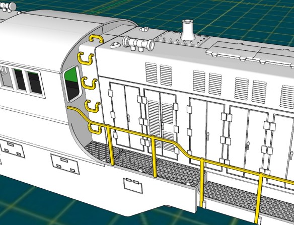
By increasing the material behind the coupler pocket I’m able to create an area for the chassis lug to fit into.  The chassis is shown in gray.

As you can see below the chassis lug has a hole in it which is 3.5mm in diameter so I’ll probably use a bolt to hold the chassis to the shell.  I can indent a hexagonal hole in the top of this new section so the bolt nut becomes captured and unable to turn.  It could even be glued in so the bolt can easily be tightened from below.  With one at each end, this will be sufficient to hold both parts together allowing the locomotive to be picked up from the body shell.

At each end, and on either side, the original DT6-6-2000 has air vents close to the walkway.  On the N Scale version, these were simply reproduced by recessing the shell to show the steel frame and the mesh, as shown below.

But for the HO version, I’ve removed the material to allow an etched brass mesh to be placed behind the frame.  This etched part will be on the ‘Brass Additions’ for this model so it only needs to be fitted.  The inside of the shell will be recessed for the mesh so the position will be correct, and it won’t catch on the chassis.

I’ll also be adding other etched brass parts to this model such as grab irons.  The N scale version had the grab irons molded as part of the shell but the HO version will have the mounting holes only, as shown below, 3D printed into the shell.

The etched brass handrails and grab irons will be made from 0.5mm brass and will have locating holes for easy and accurate assembly.

I have more details to improve and add over the next week, but something that only occurred to me today, and which I’ve decided to add, is the ability to add Preci Models DCC auto uncouplers directly to the locomotive.  Preci Models make a kit to automate a Kadee coupling, allowing it to be opened and closed via the DCC decoder as demonstrated in the video below.

I’ve fitted several of these to HO and OO locomotives with great results, but each time I had to modify the chassis or truck to mount the motor and it took a lot of fine-tuning.  I had particular trouble with HO locomotives such as the EMD GP7 and F7 because the truck is very close to the pilot, which doesn’t allow room to mount the motor.  But the DT6-6-2000 has plenty of room and I can design a pocket for the motor and a route for the actuating string.  This will not be a requirement but a great addition, as it will allow the locomotive to uncouple anywhere on the layout.  And as the DT6-6-2000 was designed as a transfer locomotive from railyard to railyard, this is ideal.

This is the perfect stage to add details and parts to the model.  Does anybody have anything else they would like to see added to the HO DT6-6-2000, or RT-624 which will be following right behind, either 3D printed or in etched brass?  Please use the contacts page to let me know.

Next week I’ll have more progress on the shell to share with you and hopefully my solution for mounting the Preci Models uncoupler.

A Baldwin DT6-6-2000 in HO – Trucks Part 2

In last week’s post, I shared with you the first steps in the HO Baldwin DT6-6-2000 project and I ended with the image below showing my 3D model of the truck centers which hold the gears in place. You can find the post here. The reason for modeling the truck centers was to allow me to work out how to reposition the gears to allow the axels to be positioned differently.  The trucks are asymmetric and I need them the other way around.

In this week’s post, I’ll share with you my solution to solve the issue.

Inside the truck centers, in the original configuration, are 5 gears, as shown below.  The green gear at the top connects to the worm gear at the end of the drive shaft.  This drives the large blue gear which turns the center and right axels, shown in black.  The center axel then transfers the rotation through the three red smaller gears to the left axel.

Because I need to move the center axel to the left, the gearing will need to be rearranged and ideally, reusing the same gears would make sense, but that wasn’t possible as you can see below.  By swapping the red and blue gears over, all the axels are connected but there’s a big gap between the green gear and the red, so another gear needs to be added in.  The purple gear is the same size as the red.  But this configuration has another issue in that the blue gear is too big for space.  Looking at the outline of the truck center you can see the shape was tapered above the blue gear’s original position and that would not be possible in the new location.  The part would either become too thin and weak or project up and hit the chassis.

So, as an extra gear was unavoidable, I decided to make four extra gears, as shown below, and remove the blue gear completely.  The four new purple gears are all the same as the red ones.  To allow space for the new configuration of the red gears, the top of the truck center will also need to be extended, but that’s okay as there’s room between the truck center and the chassis.

Both sides of the truck chassis can now be properly drawn with the new gear holes set out.

The four new gears have been modeled inside a cage to make them one printed part, even though they don’t actually touch the cage.  This reduces the cost of the 3D print.  These parts will be test printed in Shapeways Smooth Fine Detail Plastic material for accuracy.

As well as the trucks I also had to model the Bowser chassis to see if it needed to be modified in any way to fit inside the shell.  The green section is the existing circuit board, with an 8 pin DCC socket.  The black section is the motor with its two brass flywheels.  Everything else is metal.

The shell, taken directly from my N Scale version looks like this.  I’ll be refining some of the details as they don’t need to be so big for HO, and replacing some with brass parts, such as the grab irons.  I’ll also be making the grills at the bottom of each nose section from a fine brass mesh.

 With the shell split in half you can see the chassis inside and it’s a good fit, with nothing requiring modification on the chassis.  As the DT6-6-2000 is longer than the original body shell for this chassis I can update the new shell to utilize the original shell and fixing points.

Next week I’ll have some progress on the shell to update you with and once the test truck arrives I’ll share that as well.