In last week’s post, I promised to share some progress with my HO Scale Baldwin DT6-6-2000 body shell and, so far, things have gone well.
The locomotive body, as pictured below, was originally drawn for my N Scale model which can be found here. This means the bulk of the drawing work has already been done.

However, as this new model will be for HO scale, roughly twice the size, some of the details can be improved or enhanced.
There’s also scope for removing material from the shell to potentially reduce the overall cost. What I mean by this is reducing the wall thickness of the model. For example, the 3D printer I use to make my shells can print a rectangle of plastic which is only 0.6 mm thick, and when this is scaled for N scale at 1:160 the plastic translates to 96mm thick. So I designed the sides etc. of the shell to be about 96mm thick, but when this is printed at HO scale, which is 1:87, they come out at 1.10mm thick, which is almost twice as thick as it needs to be. Previously I would work through the model and thin all the walls down; I used to do that for other HO models as the price of the 3D print was based on the volume of material used. However, the method of calculating the cost has changed and there are some different rules depending on the print size. One is to do with the space the print takes up in the printer, or ‘Machine Space’, and as this is a fairly large print it’s calculated that way and a small change in the volume has no effect. A big change in volume, such as the shell being solid, would mean the volume would be used to calculate the cost and it would be higher. But for us it’s ‘Machine Space’, so I can leave the bulk of the walls as they are.
There’s also the issue of strength. The bigger a section of ‘Wall’ is, such as the side of a shell, the more flexible it will become. By increasing the thickness, the ‘Wall’ section will become more rigid and overall the shell will become stronger. Considering this is an HO locomotive and the couplings are attached to the shell and not the chassis, I want it to be strong to withstand the impact and pulling forces of a heavy train. So leaving the walls thicker is an advantage.
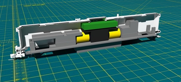
Getting back to the details, in the last post I showed the shell split in half with the chassis fitted inside, and I needed to connect the two together.
 By increasing the material behind the coupler pocket I’m able to create an area for the chassis lug to fit into. The chassis is shown in gray.

As you can see below the chassis lug has a hole in it which is 3.5mm in diameter so I’ll probably use a bolt to hold the chassis to the shell. I can indent a hexagonal hole in the top of this new section so the bolt nut becomes captured and unable to turn. It could even be glued in so the bolt can easily be tightened from below. With one at each end, this will be sufficient to hold both parts together allowing the locomotive to be picked up from the body shell.

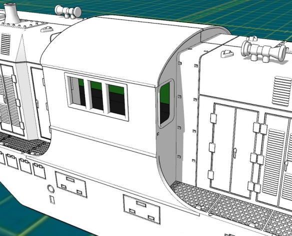
At each end, and on either side, the original DT6-6-2000 has air vents close to the walkway. On the N Scale version, these were simply reproduced by recessing the shell to show the steel frame and the mesh, as shown below.
![]()
But for the HO version, I’ve removed the material to allow an etched brass mesh to be placed behind the frame. This etched part will be on the ‘Brass Additions’ for this model so it only needs to be fitted. The inside of the shell will be recessed for the mesh so the position will be correct, and it won’t catch on the chassis.

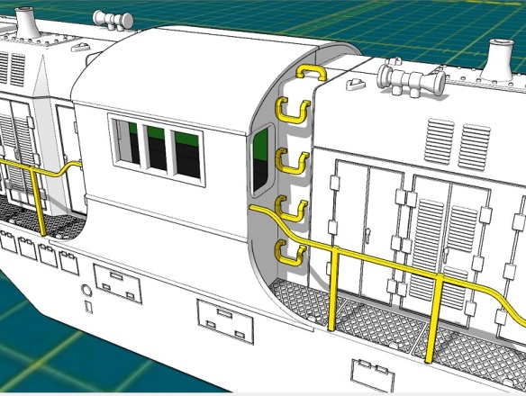
I’ll also be adding other etched brass parts to this model such as grab irons. The N scale version had the grab irons molded as part of the shell but the HO version will have the mounting holes only, as shown below, 3D printed into the shell.

The etched brass handrails and grab irons will be made from 0.5mm brass and will have locating holes for easy and accurate assembly.

I have more details to improve and add over the next week, but something that only occurred to me today, and which I’ve decided to add, is the ability to add Preci Models DCC auto uncouplers directly to the locomotive. Preci Models make a kit to automate a Kadee coupling, allowing it to be opened and closed via the DCC decoder as demonstrated in the video below.
I’ve fitted several of these to HO and OO locomotives with great results, but each time I had to modify the chassis or truck to mount the motor and it took a lot of fine-tuning. I had particular trouble with HO locomotives such as the EMD GP7 and F7 because the truck is very close to the pilot, which doesn’t allow room to mount the motor. But the DT6-6-2000 has plenty of room and I can design a pocket for the motor and a route for the actuating string. This will not be a requirement but a great addition, as it will allow the locomotive to uncouple anywhere on the layout. And as the DT6-6-2000 was designed as a transfer locomotive from railyard to railyard, this is ideal.
This is the perfect stage to add details and parts to the model. Does anybody have anything else they would like to see added to the HO DT6-6-2000, or RT-624 which will be following right behind, either 3D printed or in etched brass? Please use the contacts page to let me know.
Next week I’ll have more progress on the shell to share with you and hopefully my solution for mounting the Preci Models uncoupler.

You must be logged in to post a comment.