Drawing an Alco C-855 for N Scale Part 1

As I have said before I have a passion for the large locomotives of the Union Pacific Railroad and in this post I will share with you the first stages of my designs for Alco’s massive Century 855.

This locomotive, or rather set of three locomotives, were Alco’s answer to UP request for a 15000 horsepower set of locomotives to replace their Gas Turbines.  The Gas Turbines were becoming increasing more expensive to run.  15000 horsepower could have been obtained by simply running six 2500 horsepower locomotives together such as GP35s.  However UP were concerned that the running costs of six locomotives would be considerably higher than say three much larger locomotives producing the same overall power.  So UP approached three of the main locomotive builders of the time; Alco,  Electro-Motive Division (EMD) and General Electric (GE).

All three companies produced big locomotives for UP to trial that shared two main principles; they were all twin-engine units riding on a single chassis and they all had eight powered axles.

EMD’s offering as pictured below was the DD35, pre runner to the DD35A & DD40AX.  The DD35 was effectively two GP35 bodies joined together riding on a pair of four axle trucks. It had no cab and was used as a booster unit.  EMD’s demonstrator set consisted of two 2500 horsepower GP35 locomotives and two 5000 horsepower  DD35 boosters. Together they gave the 15000 horsepower UP were looking for.  This is a model I have already produced for N Scale and you can find it here.

EMD DD35 With Brass Etched Additions 3

GE’s offering was the U50, as shown below paired with a EMD DD35.  This locomotive was built up from a pair of U25B locomotives on a singe chassis.  The chassis and trucks for the U50 came from retired 4500 Gas Turbines that the UP had traded back to GE.  So, as with the 4500 Gas Turbines, the U50 rode on four two axle trucks grouped in pairs and connected by span bolsters.  Unlike the DD35 these had cabs and could be used as single 5000 horsepower locomotives or in a set of three to meet UP’s requirement.  The U50 below is a production model made by Con-Cor.

DD35 & U50 2

Alco’s answer to UPs request was the C-855.  The C stands for Century and this locomotive was part of their Century series of locomotive that covered everything from small switching locomotives to these massive road engines.  The 855 refers to the numbered powered axles, eight in this case, and the horsepower.  The pair of sixteen cylinder Alco 251C diesel engines put out 5500 horsepower and in 1964 this made the C-855 the most powerful locomotive for its time.

Here is a link to a picture of UP number 61 taken by Chris Zygmunt in 1967 somewhere in Wyoming.  (Picture courtesy of www.railpictures.net)

As with the U50 UP traded in retired 4500 Gas turbines but Alco only used the trucks for their new locomotive, the chassis was a totally new design.  Alco built three locomotive as their demonstrator set consisting of a pair of A units with cabs and one cabless B unit.  Together the set produced a formidable 16500 horsepower and had potential for being the dominant locomotive.  But sadly due to poor performance UP did not order any more.  The original set of three stayed in general service based out of North Platte, Nebraska for nine years before being scrapped in February 1972.

Here is another link to a photo showing the set of three from Rick C’s collection.(Picture courtesy of http://www.rrpicturearchives.net)

These locomotives are considered by many to be very ugly with their lumps and bumps and I am inclined to agree.  However I think that they are so ugly they become interesting.  These have never been mass-produced by a mainstream manufacturer in N Scale, probably because only three were ever made and they didn’t last that long.

The first thing I needed to sort out for this locomotive was the power chassis and for this I am going to use Con-Cor’s 4500 Gas Turbine/U50 power chassis as pictured below.  This made sense as the trucks are the same.

Con Cor 8500-U50 Chassis

The downside to using this chassis is it’s too short.  As Alco only reused the 4500 Gas Turbine trucks and not the chassis they repositioned the trucks further apart.  As this model is N Scale I did look at whether a bit of modeler’s license would be used, if the difference was small it may not be noticed.  But as I started taking measurements it soon became clear that there was a fairly big difference and I wanted to get the locomotive right.  To overcome this I will be 3D printing a metal extension piece to fit into the middle of the chassis.  This will push the trucks further apart but keep the motor in the middle of the locomotive.  I will cover that in a later post but you can read about how I drew the chassis ready for this in an earlier post which you can find here.

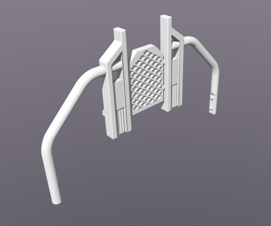
With the chassis decided upon and the modifications underway it was time to turn to the main body shell.  Working from drawings and photos that I have been able to gather I have drawn the bulk of the main locomotive.  Below are some work-in-progress shots of the 3D modeled shell.

Alco C-855 WIP Render 1 Alco C-855 WIP Render 2 Alco C-855 WIP Render 3 Alco C-855 WIP Render 4 Alco C-855 WIP Render 5There is still a lot of detail to add and finish off before it is ready to go for a test print but I am hopeful that this will happen by the end of February.  As with my previous locomotive models the C-855 will have brass Additions which will include the handrails and roof walks as well as several other small details.  The large sandboxs on the sides will also be separate parts to make painting an easier job.  The shells for both the A and B unit will be available and both will fit onto an extended Con-Cor 4500 Gas Turbine/U50 chassis.  I will also be making a dummy chassis available for each unit.

In next week’s post I will share with you the design for extending the chassis using 3D printed stainless steel.

Drawing a Chassis for new Projects

Over the Christmas period I have not done a great deal of modeling or drawing; the projects you’re waiting to see finished, such as the O Scale UP Water Tenders and the N Scale Atlas C-628 Dummy Chassis have edged a bit further, I blame the mince pies myself!  One thing I have been thinking about, whilst eating mince pies, are the projects that I will be working on in the New Year and the powered chassis which I will be using for them.  As it turns out this chassis might be a bit short so this means I will need to design a modification which can easily be inserted into the chassis to extend it. So to keep me busy I have drawn the power chassis ready to design the modification.

The new projects are going to use Con-Cor’s 4500 Gas Turbine chassis as pictured below.

Con Cor 8500-U50 Chassis

This bulky chassis is also used for Con Cor’s U50 model.  It has a single motor which powers two of the four trucks.  The two inner trucks are dummy trucks but don’t let that fool you into thinking it is underpowered, all the mass of that metal chassis makes it a good puller.

To start with I modeled the main chassis as one piece, originally thinking it would work without modifications.  However once I began to see the difference it would create in the new shell I decided it had to be drawn properly.

Con Cor 4500-U50 Chassis Render 0

So I then split it down into the two halves as shown below, taking note of all the lumps and bumps, so that when I design the extension piece it should be a good fit.

Con Cor 4500-U50 Chassis Render 1

I have also drawn the drive shafts, these will also need to be modified or extended as they will be 5mm further away from the motor.  Extending these should just be a case of 3D printing a part that plugs into the end of the gear socket.

Con Cor 4500-U50 Chassis Render 2

To make sure the chassis extension piece will fit correctly I have also drawn the motor, this is represented as a fairly basic block with the drive cogs protruding from it.  This is because all I am really interested in is its size and contact points with the chassis.

Con Cor 4500-U50 Chassis Render 3

With all the necessary parts drawn I can assemble them in the 3D model as shown below.  Having all the parts in place makes it easer to see how to design the chassis extension.

Con Cor 4500-U50 Chassis Render 4

The two halves of the chassis are separated by plastic strips, as shown below, which I have drawn in as these too may be affected by the extension. I choose not to draw the screws that hold it all together as they should not be affected and, after all, I still have the new shells to draw yet.

Con Cor 4500-U50 Chassis Render 5

Here it is all assembled in the 3D model ready to start designing the new extension modification.

Con Cor 4500-U50 Chassis Render 6

On the current chassis the two inner trucks have a center to center dimension of 51mm and for the first new model kit it will need to be 62mm.  Because the center of the chassis will be remaining in the same location it will need to expand by 5.5mm in both directions.  I will share with you how I have made the extension in a later post but for now here is a quick screen shot of one of the new shells in the very early drawing stages.

Alco C-855 Early Render 1

Now, where are those leftover mince pies…..

A Dummy Chassis For an Atlas C-628 or C-630 Shell Part 2

A few weeks ago I shared with you my designs for a dummy chassis and trucks for all those spare Atlas N Scale C-628/C-630 shells, you can find the post here.  In this post I will show you how the 3D printed parts came out and how they all fitted together.

Below is a rendering of the finished assembly including power pickups and lighting board.

Alco C-628 Dummy Chassis Render 6

The power pickups will be in the form of axle wipes as shown in the rendering below.

Alco C-628 Dummy Chassis Render 10

All the parts, with the exception of the circuit board clip, are printed in Shapeways’ Frosted Ultra Detail material and once cleaned I sprayed them with a basic locomotive black.

IMAG0588

The wipes are made from 1mm wide phosphor bronze strips.  This material is ideal for wipes as it is strong, flexible and has excellent electrical conductive properties.  To make the wiper I cut four strips of phosphor bronze; two measuring 27mm, one at 8mm and one at 6.5mm.

IMAG0590

Before I soldered anything together I test fitted the parts, as shown below.  The 6.5mm long strip is the cross-piece, it is slightly longer than it needs to be but I will trim it once I have soldered the parts together.  The cross-piece will fit under the two main wipers. I repositioned the parts and marked the main wipers where the parts intersected with a cutting knife.IMAG0591

I then soldered the first two pieces together ensuring they where perpendicular to each other.  I didn’t solder the other wiper strip on at this point because if it is not in the right place it will not slide between the wiper guides on the truck adding unnecessary drag on the axes.

IMAG0593

To get the other wiper in the correct place I added some solder to the cross strip end then I positioned the first pieces in place.  Then I placed the second wiper in place and very quickly used the soldering iron to join the two parts.  This has to be done quickly because as the phosphor bronze has great electrical conductive properties this also means it conducts heat very quickly.  The FUD material has a low melting point so if the iron is left on the joining for too long the phosphor bronze will start to sink into the truck.

IMAG0594 IMAG0595

Once the parts are joined they can be removed again and the solder joints can be renforced if required.  The cross strip can also be trimmed back; if it sticks out too far it may snag the center wheel set.  The last part to add on is the 8mm strip which needs to be soldered to the center of the cross strip.  Ideally it wants to be parallel with the wipers but it can be at a slight angle as again, if the iron spends too long on the joint the heat will quickly travel through the phosphor bronze strips and release the other joints.

IMAG0597

Once all the joints are soldered the 8mm strip needs to be bent up by 90° ensuring, as shown below, that the cross strip is above the 8mm and wiper strips.

IMAG0598

After another quick test fit the wiper assembly can be glued in place. For this I like to use Loctite’s Gel Control Super Glue, because it is a gel and so will not run all over the parts and it also gives you about twelve seconds to position the parts before it sets.

IMAG0600

The super glue only needs to be applied under the center strip, the main wipers need to be able to flex.

IMAG0599Once the wipers are fixed in place the 8mm strip will now project up through the slot in the truck next to the bolster pin hole.  This will now become the contact point to attach the wires.

IMAG0601

The next step is to fix in the wheel sets, the center set will be electrical neutral as it does not touch either of the wipers.  However it is still recommended to install it in the same orientation as the other two, that is to say that all three wheel sets have their electrically isolated wheels on the same side.  Although my 3D printed trucks have been designed to have the wheel sets fitted from the underside, the two outer wheel sets can be fitted from above, this will cause the wipers to flex naturally without being bent to get them in.

IMAG0602

Once fitted and the wheel sets have been checked to see if they move freely they are ready to be fitted onto the chassis.

IMAG0603

When pushing the bolster pins into the chassis be carefull not to break the chassis.  Once the trucks are fitted thin wires can be soldered to the contact points which will be poking through the crescent shaped slots in the chassis. At this stage I realized that only 8mm for the last strip made it a little bit tricky to solder the wires on, so on the next chassis I will make that strip 12mm long.  Even with all the parts assembled the chassis is extremely light and needs to be weighted to both improve the electrical contact with the rails and to ensure the locomotive will stay on the track.  Again I have used old motorcycle wheel balancing weights which are smaller than car ones and are ideal for N Scale.

IMAG0605

I also filled the fuel tank with weights which made the chassis the ideal weight overall.  The clip which holds the circuit board is made from Shapeways White Strong & Flexible material.  It is a lot cheaper to print than the FUD because it is a coarser material, this is ideal as the parts don’t need any visible detail.  The two halves are the same as each other and clip together securing the circuit board in place between them.  The assembly then clips into the chassis above the fuel tank.  The wires can then be soldered to the circuit board as shown below.

IMAG0606

The next step is to mount the shell, below you can see a pair of Alco C-628 locomotives in the Monon livery. One is powered and one is the dummy. I would have asked if you could tell which one was which but I think my mistake with the truck colour gives the game away!

IMAG0612 IMAG0613 IMAG0614

Both locomotives light up in the same way, the final step is to run them on a layout and I will share with you how that worked out in a later post, but for now Merry Christmas.

‘O’ What a Big Tender!

This post is about my largest print project to date.

Back in February of this year I started telling you about my designs for an N Scale 3D printed Union Pacific excursion train water tender; you can read that first post here.  The design for the 2007 to present day configuration of these tenders was very successful and below is a photo of a pair of N Scale tenders running behind a UP Challenger class locomotive.

UP Water Tenders 1

Then, at this year’s National Model Railroad Association (British Regions) Annual Convention, I introduced my HO version of this tender.  Below you can see it running with a Brass UP 844.

BR HO Modular Group With UP Tender - NMRA 2014 7

BR HO Modular Group With UP Tender - NMRA 2014 5

Then in November’s post about the Poole & District Model Railway Society’s 2014 Exhibition I told you I’d ordered my largest 3D printed object to date from Shapeways, and here it is: an O Scale tender, 1:48.

UP Water Tender 2007-Present O

This is currently my largest 3D printed item, and I’ve had two of them printed.  Both Jim Adams and Joe Jordan.

As usual the project starts with a 3D model, as shown above.  For the O scale tender I was able to take the HO model and rework it.  I could have used the HO model as it was but this would mean the material would have been twice as thick as it needed to be and although that would have made it very strong it also would have made it very expensive.  Shapeways, and other 3D printing bureaus, charge by material volume to produce prints.

This model will also be different to the HO and N Scale kits I have produced because I will not be supplying a chassis or any trucks with the kit. This is because these are available from Lionel as spare parts for their Union Pacific Water Tenders: you can find the parts here.

Here are the Lionel chassis assembled with truck and couplers.

O Scale Tender - Lionel ChassisUsing these chassis has two great advantages, the first being that they are cheaper to buy than to have 3D printed, and secondly, they are very heavy and strong.  This is important because in O scale the load which is put on to the couplings and chassis is immense compared to HO and N scale trains.  These metal chassis will take all the strain.

The trucks still need to be removed and disassembled so they can be sprayed silver to match the UP tender in its Armor livery.

The other detail parts which I will be using on the O scale tenders, as seen below, are cut levers, cut lever support brackets, and brake wheels on stands.  On my N & HO scale tenders these are part of the 3D printed body.  (Cut levers are used in the US on the ends of most rolling stock.  It is a lever which allows railroad workers to manually release the couplings between the cars and cutting the train, without going between the cars).

O Scale Tender - Lionel Parts

Having the cut levers and their supporting brackets as separately applied details for this model was very useful. If the cut levers had been 3D printed it would mean that the print would be too long for the printer, it really was that close.  As they are now separate parts the reduction in length at each end was just enough and the model now fits.

The handrails on top of the tender can also be printed in situ as they are twice as thick as the HO ones and consequently a lot stronger; if the HO handrails are printed in situ there is a good chance that they will be broken in the cleaning and shipping process.

Below you can see all the parts as they are delivered from Shapeways.

O Scale Tender - Kit x2

O Scale Tender - Kit

Detail parts such as the ladders, tool boxes, flag plates and headlights are still printed as separately applied parts.  This helps with painting and finishing the model.

O Scale Tender - Kit Parts.jpg

These tender kits have been printed in the Shapeways Frosted Detail material.  This has a layer thickness of 32 microns and although it is not quite as sharp as the Frosted Ultra Detail at 29 microns in O scale none of the detail is distorted or missing.

O Scale Tender - Raw Shells

O Scale Tender - Raw Detail 1 O Scale Tender - Raw Detail 2 O Scale Tender - Raw Detail 3 The main test for the shells was to make sure they fitted onto the Lionel chassis, and they dropped right on. The tool boxes on top of the tenders in the images below have already been cleaned ready for painting which is why they are opaque.

O Scale Tender on Chassis - Raw 2 O Scale Tender on Chassis - Raw 3 O Scale Tender on Chassis - Raw 5

The next step is to clean up the main bodies ready for painting. This was a bit more tricky than normal as these are somewhat bigger than my normal 3D printed objects. To give you an idea of just how big they are in O Scale, below is a picture of the N Scale tender with the HO one…

O Scale Tender - Comparison 1

…and then again with the O Scale one behind.

O Scale Tender - Comparison 2

With the second O Scale tender in the mix the scale of these starts to become clear.

O Scale Tender - Comparison 3

O Scale Tender - Comparison 5 O Scale Tender - Comparison 4

Cleaning the O Scale tenders is going to need a much bigger container!

In a later post I will share with you the finishing process and photos of the completed tenders with all their detail parts applied ready to make their way to their new owner.

A Dummy Chassis For an Altas C-628 or C-630 Shell

With the launch of my most recent locomotive shells, the Baldwin RT-624 and the popular Baldwin DT6-6-2000, there must have been a lot of surplus shells left over from the donor locomotives.  In this post I will share with you a new product that will allow these spare shells to be used.

Both the RT-624 and the DT6-6-2000 use the same donor chassis from an Atlas C-628 or C-630, it’s the same chassis in both.  Here is one of my C-628 locomotives that sacrificed it’s chassis for my first DT6-6-2000.

Atlas C-628 1

The shells on these locomotive are very nice and it would be a shame not to use them.  The huge fuel tank and truck side frames are also not required as donor parts which means the bulk of the locomotive is intact.  Here is the locomotive disassembled.

Atlas C-628 3

Re using the trucks or side frames would be a bit tricky as they are designed to clip onto the Atlas power truck but the main shell and fuel tank can easily be reused.  For this a chassis is needed.  For my DDA40X dummy chassis I used Shapeways White Strong & Flexible material as it has a low-cost for volume and that a was big chassis.  That dummy chassis was fairly simple and did not need a lot of detailed sections so the courser WS&F was not a problem.  For the C-628 chassis I will be using Shapeways Frosted Ultra Detail material.  This is because it allows for very accurate detail and that will be needed to replicate the same fixings points used on the original chassis.

To start I used the 3D model chassis I created to fit the DT6-6-2000 shell on to, as shown below.  The chassis is modeled at the right hight from the rail head and I have included all the groves and bumps.  The C-628 cab fits over the lower section on the left.  The fuel tank clips onto the horizontal slot as well as having fins that fit into the vertical slots, they are not centered so the fuel tank will only fit on one way round.

Alco C-628 Dummy Chassis Render 1

Next I created a chassis model using as little material as possible whilst retaining the strength, the material is not as cheap as the WS&F and very light so there in nothing to be gained by bulking it up at this stage.  Weight will need to be added but as the fuel tank is hollow, with a bottom, it can be filled with scrap bits of metal.

Alco C-628 Dummy Chassis Render 2

Next we need some trucks. I copied the side frames from the atlas trucks, and added a bit more detail from photographs of the real locomotive as shown below.  The raised section around the hole is the pivot point where the bolster pin passes through the truck.  Normally the pivot point is in the middle of the truck or over the center axle, but this would create two problems.  Firstly the center wheel set would need to be removed every time the truck needed to come off and secondly as the truck rotated it would hit detail which hangs down from the atlas shell.

Alco C-628 Dummy Chassis Render 8

The underside of the truck has four sets of forks sticking out of the middle.  These have been designed to allow 1mm phosphor bronze, or similar, metal strips to be fixed to the truck and make axle wipers.  The forks stop the axle wipers from touching the wheels and causing a short circuit.  The forks can be seen in the image below as well as a slotted hole in front of the bolster pin hole.

Alco C-628 Dummy Chassis Render 9

The image below shows the ‘H’ shaped set of axle wipes fitted to the truck as well as the wheel sets, I am using Fox Valley metal wheel sets that have one insulated wheel.  The two outer wheel sets pick up power from one rail and the middle wheel set is electrically neutral.  The wipers are made from four strips of phosphor bronze and once soldered together will be glued into the truck.

Alco C-628 Dummy Chassis Render 10

With the truck set back on the track you can see the fourth strip of phosphor bronze poking through the slotted hole, the bolster pin is also visible in the image below although it would drop out of the real truck without being pushed into the chassis.

Alco C-628 Dummy Chassis Render 11

Both trucks are the same but as they are asymmetric one is rotated by 180° as you can see below.  There is a crescent slot at each end of the chassis to allow the phosphor bronze strip to stick up without preventing the truck from rotating

Alco C-628 Dummy Chassis Render 3

You may be wondering why I have added electrical pickups to a dummy locomotive, well as all of my DT-6-6-2000 and RT-624 locomotives have been converted to DCC the old circuit boards are also surplus.  I intend to use some of my dummy C-628 locomotives as pushes on the rear of long trains and they need to have lights.  As the circuit board puts the mounted LEDs in the right place it makes sense to use it.  However as you may remember from the view of the 3D modeled power chassis the circuit board sits along way up from the top of my 3D printed chassis. To solve this I have designed a pair of circuit board clips as shown below.

Alco C-628 Dummy Chassis Render 12

These are printed in Shapeways WS&F material so they are really cheap, they are designed to clip together holding the circuit board in place, then they clip into the 3D printed chassis as shown below.

Alco C-628 Dummy Chassis Render 4

The last thing to do is run a wire from the phosphor bronze strip to the power connection on the circuit board.  If run as is on a DC locomotive the lights would work just as they did with the power chassis fitted.  If the polarity of the wires is reversed and the LEDs swapped for red ones this will work as tail lights.  A DCC light decoder could be fitted or even a sound decoder.

Alco C-628 Dummy Chassis Render 6

I have already printed this dummy chassis and it was fairly successful, the issue I had with the kit was some of the detail on the truck was catching some of the detail on the shell.  With a bit of cutting and filing the problem was solved.   Here it is pushing behind a long coal train on Ant Quinlan’s wonderful layout, Horsethief Bridge, at the NMRA (BR) convention 2014.  You can read more about the layout here.

Horsethief Bridge NMRA 2014 - Monon Interloper 1

Until the alteration was made, it struggled on tight curves but that was soon fixed, Ant and I also experiments with adding weight to the shell, we found 3 bolts was just about right!

The added weight gave the dummy stability and it tracked round the layout well.  Below is a video of it running behind the coal train as a pusher.

And here is another video of it working as a mid train helper.  Ant’s rolling stock was all weighted so there was a fair tonnage being pulled through the dummy locomotive but it did the job without trouble.

Since the first 3D print was tested I have corrected the issues with the clashing details and fine tuned a few other areas.  The next 3D print has been ordered and should be here later this week.  In a later post I will show you step by step the assembly of the axle wipers, adding weight, painting and finishing the dummy locomotive. The dummy chassis kit will then be made available for anybody that wants to use their spare Atlas C-628 and C-630 shells.

Drawing a Baldwin RT-624 for the Pennsylvania Railroad

Earlier this year I designed an N Scale shell for a Baldwin DT-6-6-2000 transfer locomotive.  You can read about it here. This locomotive type was later refined by Baldwin and became the RT-624.  In this post I will tell you a bit about the RT-624 and share with you the design for the new locomotive.

The RT-624 is the natural development to the DT6-6-2000.  Built between 1951 and 1954 the locomotive was still classed as a transfer unit, designed for moving strings of freight cars between local yards in big cities.  It was a heavy locomotive giving it great traction, plus it had, for its time, a lot of horsepower.  Baldwin had started changing their naming convention for locomotives by this stage; this locomotive was sometimes called a DT6-6-2400 but Baldwin’s correct name was RT-624.  RT stands for ‘Road Transfer’, 624 stands for 6 wheels per truck and 2400 horsepower.  To achieve the extra 400 horsepower Baldwin replaced the pair of 606SC supercharged diesel engines with their newer 606A supercharged diesel engines.  These each produced 1200 horsepower and were more reliable.

Baldwin also moved some of the air vents and grill work on the side to help with air flow around the engine compartments. The DT6-6-2000 was almost symmetrical but the RT-624 had one walkway that was a different shape to the rest. This one had a longer raised section allowing for more battery storage under the walkway.

Baldwin made twenty-four of these behemoths; one was purchased by the Minneapolis Northfield & Southern and numbered Twenty Five.  Here is a picture of it taken on the 21st of June 1964 at Glenwood Junction, MN by Marty Bernard (www.rrpicturearchives.net).

You can see it very closely resembles the DT6-6-2000, the headlight is lower and you can see where Baldwin has lowered the grills.

The other twenty-three were purchased by the Pennsylvania Railroad.  The first fourteen, built in 1951 and numbered 8952-8965, ran on the same Commonwealth Trucks as the DT6-6-2000.  Here is a photo of 8963 taken on the 21st November 1966 in Pitcairn, PA by Ryan Kertis.  (www.rrpicturearchives.net).  8963 did not have a lowered headlight but it did have additional grill work on the sides.  You can also see on the right of the photo the walkway runs at the higher level for longer, creating the larger space.  Also apparent in this photo are the antennae on the roof for the uniquely PRR train phone system.

The next eight, built in 1952 and numbered 8724-8731, ran on newer Outside Equalized Trucks.  Here you can see loco number 8728 and an unknown sister engine. The photo was taken on the 17th of July 1965 at Porter, DE by Jeff Van Cleve. (www.rrpicturearchives.net). In the photo you can see the lowered headlight and single lowered grill as well as the newer Outside Equalized Trucks.  Also the end handrails have been revised to include a folding down walkway allowing crew to move between locomotives when double heading.

Here is another photo of a pair of PPR RT-624s.  Taken on the 6th June 1961 at Paoli, PA by James Gillin. (http://rrpicturearchives.net).

The last locomotive, number 8113, was built-in 1954 and was the same as the previous eight.

The model I have been working on will be based on the PRR locomotives built in 1952 with the Outside Equalized Trucks.  Because the donor chassis will be the same, an Atlas C-628/C-630, and because the basic shape is the same the majority of the model has already been drawn.

The first job was to move the grills on the ends, in the image below you can see the grills in their new position.

Baldwin RT-624 Shell

This image also shows the modified walkway on the left hand side with the storage space below as well as the lowered headlight.  The PRR also mounted their number boards in a different place than the Santa Fe on their DT6-6-2000, you can see the oval number board on the side of the main body above the first set of engine doors.  The main body also has some different detail parts on the nose and the roof that have been added as well as shorter exhaust stacks.

The new truck side frames have been draw from scratch although I was able to use the same mid section where the truck clips onto the Atlas chassis truck. Baldwin RT-624 Shell 2

Baldwin RT-624 Truck RenderThe PRR train phone antennae were a bit more tricky to do.  Given the size they would need to be if 3D printed I felt that they would look way too chunky and very unrealistic. So these have been made as separately applied brass detail parts.  Only the section of antenna which is raised off the roof on posts is an added detail, the cable section that runs down and around the cab windows are molded into the main body as shown below.

Baldwin RT-624 Shell 4

The handrails are again printed inside the main body to protect them and will need to be cut out and removed from their sprue before they can be applied.  The new end handrails come with the new link walkway attached.  Below is the view from the inside.

Baldwin RT-624 Shell 5

And here is the view from the outside.

Baldwin RT-624 Shell 6As with my DT6-6-2000 I am also offering a brass Additions kit for this locomotive which will include all the handrails, two roof antennae, two sun visors and four air pipes which can be added as an extra detail next to the coupling.  I have supplied four because I think gluing two together before they are installed will give the desired thickness.

Baldwin RT-624 Additions Render

Unlike the DT6-2-2000 the fuel and air tanks are visible on the RT-624.  This is because the RT-624 does not have the large flange plates which hung down on the DT6-2-2000.  This means that the lower section of the Atlas C-628/C-630 chassis will be visible so I have drawn a replacement fuel and air tank section which will clip onto the Atlas chassis using the same fixing points.

Baldwin RT-624 Shell 3

When the locomotive is assembled, it will look like this. Baldwin RT-624 Render 1 Baldwin RT-624 Render 7 Baldwin RT-624 Render 6 Baldwin RT-624 Render 4 Baldwin RT-624 Render 3 Baldwin RT-624 Render 2Baldwin RT-624 Render 8The 3D printed kit will be available from my Shapeways shop printed in the Frosted Ultra Detail material and the brass Additions will be available directly from me, please contact me through the contacts page.

This will also be the first kit that I will be offering in a higher print quality than the Shapeways FUD material.  This will come from a 3D print bureau in London which is offering custom one-off print runs.  The Shapeway FUD material prints at a layer thickness of 29 microns or Ultra High Definition (UHD) which is still far better than just about any other 3D printer currently available.  However it is now possible now to get this kit printed using the same 3D printer but at a 16 micron layer thickness.  This is called Extreme High Definition (XHD).  At the XHD print setting, the layering effect that can sometimes be seen on all 3D prints, is greatly reduced.  Another advantage to using this 3D print bureau is they allow you to specify the orientation of the model; this is important, because if a model is printed upside-down, detail which is resting on the build plate may not be as clear as detail on the top of the print.

However this service does come at a cost.  The XHD model is three times the price of the UHD or FUD from Shapeways.  This is because the print time is greatly increased due to the higher number of layers which need to be printed.  Also because of the orientation, the main body of the locomotive has a large space inside which needs to be filled with support material in order to print the roof of the shell.  At this high level of printing the support material is nearly as expensive as the build material.  Companies like Shapeways can reduce the print cost to the customer by using this space to print other models; if the models are packed densely in the print tray, less support material is used which brings the cost down.

The test print for this model is currently printing at Shapeways in FUD. Once I have received and checked everything fits okay I will make it available in both FUD from Shapeways and XHD direct from me.

If you are interested in a XHD print please contact me through the contact page.

In next week’s post I will share with you another new product which will make good use of any spare Atlas C-628 or C-630 shells.