Bridging The Gap Between Materials Part 2

Last weeks post was all about my designs for combining 3D printed parts and timber to scratch build a trestle bridge; you can find the post hereThe 3D printed parts have now arrived and in this weeks post I will share with you how they came out, and what the are like to work with.

The module I am building is for N Scale and has three trestles bridges although the last two are joined at one end. Below you can see a 3D computer rendering of the proposed module without scenery.

Trestle Module 1The parts of the trestle that are 3D printed are the main decks or stringers. Below is a 3D rendering of the underside from my computer model.  The cross ties you can see are guides to correctly position the top of the trestle bents (legs).

Trestle Stringers 2

The parts have been printed by Shapeways in their White Strong & Flexible material and below are some photos of how they look when they arrived.

WS&F Trestle Parts 1 WS&F Trestle Parts 2 WS&F Trestle Parts 3

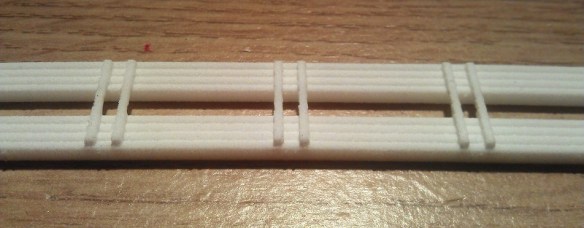
The three photos above show the short trestle stringers from the left hand side of the module.  The images below are the three parts that make up the large trestles to the right of the module.  The longest span from the front of the module has been split in two to make it easier to print and ship.

WS&F Trestle Parts 5

As you can see in the image above, none of the sections are straight, so having them 3D printed allowed me to ensure the trestle followed the correct path and landed at the right spot on the other side of the module.  As expected, the accuracy of the 3D printed parts was perfect, and when I laid the parts over a scale drawing I had printed out, they were a spot on match.

To join the two ends of the long trestle section together, I designed a finger joint into the middle.  Each stringer is made from four timbers. So as you can see in the image below, with the top section, I lengthened the middle pair and shortening the outside pair.  This was reversed on the connecting section.

WS&F Trestle Parts 6

Because I wanted a good tight and strong fit I did not allow any tolerance between the parts intending them to be held in place by friction as well as glue.

WS&F Trestle Parts 7

In the test fit below you can see they fitted very well.  To permanently fix these parts together I used tacky wood glue (white glue) in the joint, push fitted them together on a flat surface and left them overnight.

WS&F Trestle Parts 8

Although this material has a nice roughness to it which helps it look like timber the shocking bright white color does not. This is very easily resolved and in the same way I colour my timber for the rest of the trestle.

A have done this several times before as I have scratch built timber trestles before, although entirely out of wood, such as the one below.  This is part of the James Canyon Trestle on the Golden State Model Railroad Museums’ massive N Scale layout.  You can see more shots of it in the gallery here.  This trestle is made from bass wood and was stained rather than painted.  I used Woodland Scenics‘ Burnt Umber C1222 to stain the timber and black weathering powder at the intersections.

WP over James Canyon Trestle

A good supplier of Bass wood is Black Bear Construction who specialize in scale lumber and jigs for making trestles in all scales.

Because the bass wood is stained rather than painted the hue of the colour can easily be varied depending on the amount of stain you use.  I also recommend staining all your timber before building the trestle, this is much easier than trying to get a brush into all those tight spaces.

For my new trestles I am using balsa wood.  This is not as strong as bass wood but I have a good supply and I was able to cut all the required scale sizes at Model Railway Solutions here in the UK.  It was partially because balsa is not as strong as the bass wood that I decided to 3D print the main deck or stringers; at this scale the WS&F material is much stronger than wood.  Surprisingly dispite its softness, balsa wood is a hard wood. Hard woods and softwoods are designated from the family of tree not from a hardness test.

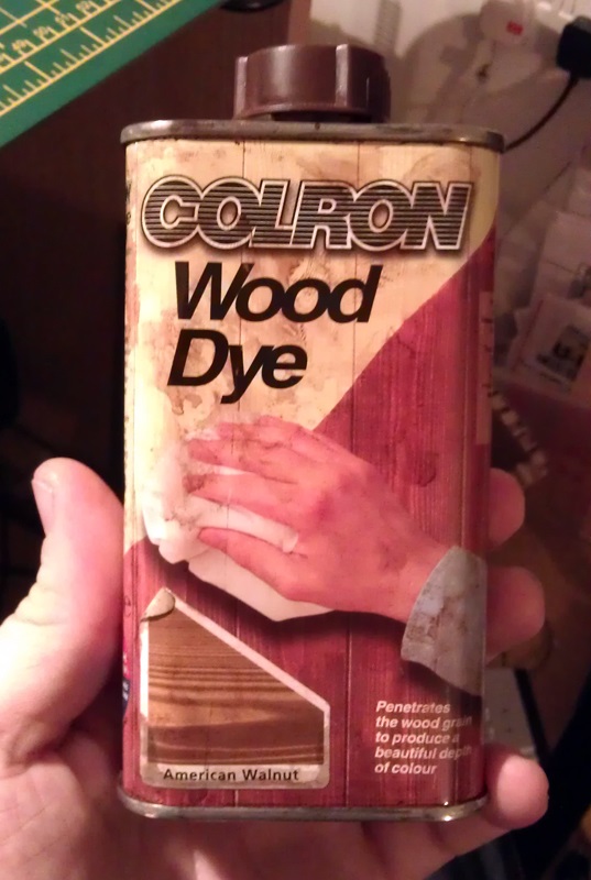
Again I used a stain, or in this instance, I used American Walnut wood dye from Colron.

WS&F Trestle Parts 13 As with the balsa wood, the WS&F material is very absorbent to paints and stains and sucks up the color.  A small amount on a brush when touched to the WS&F will cover a big area and just about seeps through to the other side.  As with the bass wood trestle, you can get different hue effects by altering the amount of stain or dye applied.  Below are some shots of the stained decks or stringers.

WS&F Trestle Parts 9 WS&F Trestle Parts 10 In hindsight, I should have stained the two long trestle sections before I glued them together.  The tacky wood glue I used forms a barrier that the stain will not penetrate or cover,  so at the joint there are some white spots as you can see below.

WS&F Trestle Parts 11 WS&F Trestle Parts 12 However this can easily be covered with brown paint and weathering, so when finished it will not be visible, but this is a good reason for staining all the parts first which I did with all the rest. Construction could then begin.  Below are some shots of parts of the smaller trestle in place. It is not finished yet as there are still lost of braces and details to add, but it gives you a good idea of how the 3D printed parts and the balsa work together.

WS&F Trestle Parts 14 WS&F Trestle Parts 15 WS&F Trestle Parts 16 WS&F Trestle Parts 17 WS&F Trestle Parts 18 WS&F Trestle Parts 19 WS&F Trestle Parts 20 WS&F Trestle Parts 21

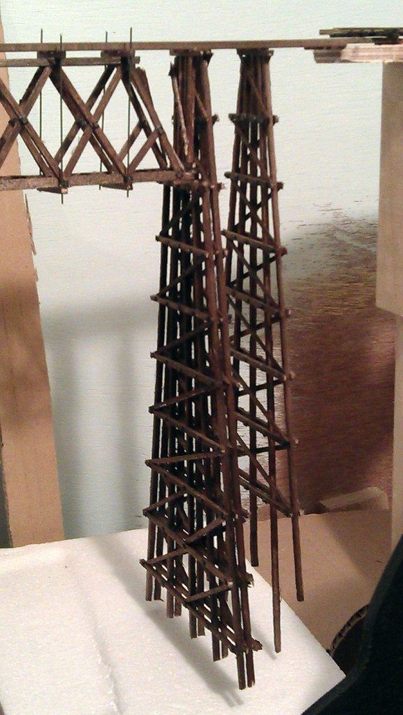
I now have a lot of bents to make and landscape to form to complete the trestle which will keep me busy, but I will share my progress with you in the coming weeks. This module will be finished for this year’s NMRA (BR) annual convention in Derby later this year and will be part of the Gosport American Model Railroad Group’s layout Solent Summit.  Maybe I will see you there.

Bridging The Gap Between Materials Part 1

With 3D printing becoming more and more useful in the model railroad world I have started to look at the scratch built projects I am working on and wonder how I can use 3D printing to do the same job.  This has been great for projects which need complex parts or very bespoke and detailed items.  But sometimes simply making them with a 3D printer can take some of the enjoyment out of model making.  A good example of this is bridges, or to be more precise, timber trestles.  I have always enjoyed scratch building trestles using real wood and in this post I am going to share with you how I have combined 3D printing and real timber to scratch build a new trestle.

The project I am currently working on is a module for the Gosport American Model Railroad Groups N Scale layout.  The module, called Warsash Wye, is five feet long and one foot deep and has a ‘U’ shaped river running through it. Below is a computer model of my module and you can see the river bed at the bottom.

Trestle Module 2

As the railroad passes through the module it crosses the river twice and also has a diverging line that splits off and runs out of the back of the module.  Below is a plan view showing the track centers.  The diverging line also crosses the river before entering a rock tunnel.

Trestle Module 3

I wanted to create a scene similar to the famous Keddie Wye trestle, which is near the California and Oregon border, but using timber instead of steel.   As with the Keddie Wye the diverging tracks leave the turnout directly onto the trestle high above the river.

There are all sorts of ways to make a timber trestle but the fundamentals are always the same.  There is a main deck or floor that the track is fixed to; it is made from timber sat on a pair of timber stringers which run the length of the trestle.  The stringers are then supported on sets of timber legs called bents.  The bents are spaced at typically 14′ intervals and braced together with horizontal timbers called girts and diagonal timber bracing.

In the computer model below I have placed typical bents in the correct place leaving gaps where the river runs through.  These gaps will have bridge sections built into the trestle. Where the two trestles run together the bents will be twice as wide supporting both parts.

Trestle Module 1

Very little of the trestle is straight, by design, and to accurately space out the bents the set out would normally be fairly complicated.  But with the computer it is a fairly simple operation.  Each line extending off the drawing below represents a change in the radius of the trestle deck.  At the end of each line is the center of the curve.  By using this geometry I can set out all the bents so they are all perpendicular to the stringers in the computer model.

Trestle Module 4

I have made curved trestles before and one of the issues I had was ensuring the bents were all evenly spaced and perpendicular around the curve.  Even though I have set this trestle, out on the computer when it comes to making it there is still a chance of getting the spacing wrong, so to make this trestle easy to build I am going to 3D print the stringers and scratch build all the bents out of timber.  The girts and bracing will also be made from timber

Doing this has several advantages.  Firstly, by 3D printing guides onto the stringers I can ensure all the bents will be set out correctly.  Secondly, curved stringers can be complicated to make and 3D printing them will greatly decrease the construction time and increase accuracy.  Thirdly, as this module will be regularly transported around, having the stringers made from one piece will help protect the trestle by strengthening it, as well as ensuring it holds up to the biggest rolling stock and locomotives we have.

Normally the stringers are made from three or four timbers with packers between them.  Considering that this trestle is for N Scale and also to give them strength I have made the stringers solid along their length instead of making the packers intermittent.  Below is a cross-section through the stringers.  I have also modeled the bolts that run through the stringers at the pack locations.

Trestle Stringers 1

The two stringers are tied together by the guides as shown in the images below, the stringers are shown upside-down.  These have been positioned so the top bent timber, known as the top cap, fits between them.  In the image below there is a triple set of guides.  This is because at this location there will be a double bent as this will be where the trestle crosses the river.

Trestle Stringers 2

I have also notched the end of the stringers so they will lap over the end of my bench work. My track is laid on top of a cork road bed and when the trestle is fitted in place the top of the trestle will be at the same level as the top of the cork allowing a smooth transition.  Below you can see a close up of where the trestle will meet the bench work and a double bent.

Trestle Module 6

With all the geometry worked out and all the bolt details and notches modeled the parts which will form the trestle deck can be separated out and sent off to be 3D printed.  Because the largest part of the trestle will be very long I have split it in two.  Where the two ends are to be joined together I have designed them so they will finger together for strength.  You can see one of these connections at the bottom right of the image.

Trestle Stringers 3

These parts have now been 3D printed in Shapeways’ White Strong & Flexible material.  I chose this material because it will be, as the name suggests, strong.  It is also fairly cheap as it’s Shapeways’ basic material.  The level of detail is not as high as their other materials but for my purpose that is not a problem as the top will be covered with track and I want it to have a weathered wooden look rather than a crisp finish.

These parts have now been delivered and in next week’s post I will show you how they came out and what I did to make them look like timber, blending them into the rest of the trestle.

Replacement N Scale Horns

As a lot of my N Scale diesel locomotives are older and have been acquired from train shows over the years, a few of them have, at some point, lost some of their detailed parts; particularly their horns.  So every now and then as I am ordering parts for other projects I have been drawing up horns and adding them to the order so that I can repair my fleet.

Below is a rendering of some horns originally drawn for the Baldwin RT-624.  The horn on the left is the one which comes with the RT-624 kit.  I rotated one of the cones to make a bi-directional set to use on another switching locomotive which has been with out horns for a while.

N Scale Horns Render

Each set has a peg in the bottom so it can easily be inserted into a hole in the locomotive shell.

Although these are very small they printed very well in Shapeways’ Frosted Ultra Detail material.  I did have to make a few sacrifices with size in order to meet the minimum printable thickness but overall I am happy with the result.

N Scale Horns 1 N Scale Horns 2

Once the last of the powdery residue has been removed and they are sprayed the right colour I will fit some to my locomotives.  Below is a photo of one sat on an atlas GP loco to give a size comparison, I think they will be just fine.

N Scale Horns 3

The next set of horns I need is for a Life-Like Alco FA2.  This are single cone horns and I will be drawing a set and adding it into my next order.  Given the size of a single horn I will probably need to join them together for the print processes.  Then they can be cut apart and fitted into the holes in the FA2 cab roof.

Once I get a good selection of horns drawn and printed I will make them available too buy through Shapeways in packs.

Replacement Eccentric Rods for a MRC/Rowa N Scale 2-8-4

As well as the complete locomotive shells and bigger kits I also use 3D printing to make replacement parts for a whole number of repairs and improvements to my trains. In this post I will share with you my 3D design to replace a missing part from an old MRC/Rowa 2-8-4 steam locomotive.

The 2-8-4 Berkshire locomotive, pictured below, was made by Rowa who were a German manufacturer of European model trains. In 1969 they released this US model along with their impressive 2-8-8-2 Y6b. Both these models were imported to the US and sold by Model Rectifier Corp (MRC) and were very popular as they were and still are good locomotives. Compared to today’s offerings they are a little bit dated and smooth running at slow speed can be hard to achieve. There is no DCC readiness but a conversion is not tricky to do and they are still good-looking models; and if still running well are also reasonably good pullers.

Rowa 2-8-4 Berk Acc Rod 1

Around 1977 Rivarossi acquired the tooling for this model and re-released it using Con-Cor as the importer.   Rivarossi made some improvements to the locomotive; the relevant one to this post was to the side rods and valve gear of the locomotive. Rowa’s locomotive had plastic side rods and valve gear which were colored gray. Rivarossi changed this to metal.

My 2-8-4 is one of the early ones made by Rowa with the plastic side rods and valve gear. As I have often seen when looking at second-hand Rowa 2-8-4 models the eccentric rod was missing from one side of mine. Below you can see one side with the eccentric rod and one side without.

Rowa 2-8-4 Berk Acc Rod 3

Rowa 2-8-4 Berk Acc Rod 2

The eccentric rod drives the valve gear in the top of the locomotive steam cylinders. This opens and closes the valves at the right position to allow steam to push the main rod in and out of the piston chamber. Although the eccentric rod has no real effect on the running of this model locomotive it is an important cosmetic part; the real locomotive could not operate without it and I would like to see this locomotive working properly.

The original plastic eccentric rod simply clipped into the C shaped mounts you can see in the photo above. There is one offset on the third driver, where the main rod connects to the side rod. The other is between the first and second driver just under the bell crank. The plastic eccentric rod has pins on the rear that fit into the C shaped mounts. It fits with a snap and the C shape holds it in place but allows it to rotate. Below is one of the eccentric rods removed from one of my other Rowa 2-8-4s.

Rowa 2-8-4 Berk Acc Rod 4 Rowa 2-8-4 Berk Acc Rod 5 Rowa 2-8-4 Berk Acc Rod 6

I think it’s because the eccentric rods can snap out so easily that so many are missing from the secondhand models.

This was a very quick 3D model to draw and I was able to keep the part sizes the same as the original Rowa part without going below the recommended sizes for the material I want to use.

Oddly enough the pins on the rear of the eccentric rod are not in the center of the rounded ends but offset towards the ends as you can see from the rendering below.

MRC Berkshire 2-8-4 Eccentric Rod Render

These will be test printed in Shapeways Frosted Ultra Detail material which will give the best detail and should also ensure a smooth surface on the rod. As these parts are very small they can’t be printed individually so when I make them available it will be pairs.

These should be going to test print soon along with other small parts like the O Scale F9 gears from last week’s post. Once I get them I will share with you the results as well as some video of the new 3D printed eccentric rods powering my Rowa 2-8-4 Berkshire.

New Gears for an O Scale Rivarossi F9

A few months ago at the NMRA (BR) convention in Bournemouth I was asked by a fellow modeller, Mike Dobson, if 3D printing could be used to produce some replacement gears for one of his O Gauge locomotives.  In this post I will share with you how we achieved just that.

The locomotive in question is a Rivarossi O Gauge F9; although the test locomotive is a Red Caboose GP9 shell with a Rivarrossi F9 chassis in it.  Below is a shot of the locomotive on Mike’s layout.

Rivarossi F9 (O Scale Gears 3 (Mike Dobson)

The gear which Mike wanted printed is the final gear in the transmission.  This is the gear is on the locomotive axles.  The original plastic gear had split, as you can see in the picture below, and no longer clamped onto the axle but simply spun in place.  The gear is press fitted onto the metal axle and friction between the plastic and the metal means the axle will rotate with the gear.  The plastic Rivarossi used for their gears is rather brittle and it’s a common problem for this to split like this.

Rivarossi F9 O Scale Gear

The first thing to do was to measure and draw the gear in the 3D model.  Below is a rendering of a pair of gears.

Rivarossi F9 Scale Gears Render

Then it was off to the printer and for these gears I used Shapeways Frosted Ultra Detail material, the first set is shown below.  As well as being Shapeways highest detail material it is also one of the most accurate.  And it has very similar properties to the original gear material although not so brittle, but mainly that it has a hard finish so should be long wearing. I felt that the White Strong & Flexible material, despite being cheaper, may lead to the gear teeth being uneven and also may wear down very quickly.

Rivarossi F9 Scale Gears 1

With the gears successfully printed it was time to try them out on the F9 chassis.  Below you see the underside of the F9 with a new 3D printed gear on each chassis axle.  As this was the first run of gears there was a bit of trial an error involved with the fit onto the axle.  If the hole through the middle was too small then pushing the gear onto the axle will cause the gear to split.  If the hole is too big there will not be enough friction to rotate the axle.  With the first print I was slightly too big on the hole.  This has now been corrected and the next set should be spot on.  However the main test was to see how well the 3D printed gears stood up to the punishment of an O Scale motor so Mike friend and fellow O-scaler Steve Morris reamed out the gears and fitted a brass sleeve inside.  The gear was now a tight fit onto the sleeve and the sleeve was a tight fit onto the axle.

Rivarossi F9 (O Scale Gears 1 (Mike Dobson)

Below are some close-ups of the gears in place and you can just make out the brass sleeve.Rivarossi F9 (O Scale Gears 2 (Mike Dobson)

Rivarossi F9 (O Scale Gears 5 (Mike Dobson)

With the gears in place and the locomotive fully reassembled it was time for a test.  As well as the nicely scened sections of Mike’s layout he also has a staging area above which is reached by a 2.5% curved grade.  You can see this below along with Mike’s test train of six loaded ore cars, four box cars and a caboose.  This grade also forms part of a continuous run so the test locomotive could be left to trundle round with its train for a few hours.  This was a good check for wear on the gears, and after several hours there was none. Rivarossi F9 (O Scale Gears 4 (Mike Dobson)

Here is video of the train running through the station and then up that curved grade.

The second set of gears with the correct hole size will be going to print soon and Mike will be doing some more tests with them.  Once we know that they are correct I will make them available for everybody who needs replacement gears for their locomotive.

If you have similar gears on a locomotive that need to be replaced and would like to try a 3D printed replacement please contact me through the contact page or drop me an e-mail.

Drawing an Alco C-855 for N Scale Part 2

In last week’s post I started showing you how my new N Scale project is coming on, Alco’s C-855.  And as promised in this week’s post I am going to show you how I intend to lengthen the donor chassis for this locomotive.

The chosen chassis, as modeled below, for the C-855 is going to be Con-Cor’s 4500 Gas Turbine/GE U50 chassis.

Con Cor 4500-U50 Chassis Render 6

Although the chassis has the right trucks etc for the C-855 they are at the wrong centers and need to be spread apart by 10mm.  That doesn’t sound a lot but in N scale it can make a huge difference visually, it’s 1.6 meters (5′ 3″) on the real locomotive.

I looked at several ways to do this and each time found a reason why it couldn’t be done that way.  The main issue is the motor; it is centrally positioned in the chassis with two drive shafts powering the two furthest sets of trucks.  The two inner ones are not powered.  Spreading the trucks will also mean the drive shafts will no longer reach them. And if only one end is lengthened it may cause an unbalanced load to be applied to the motor.  The motor hangs down in the frame and on the 4500 Gas Turbine/GE U50 this is concealed by a fuel tank mounted between the trucks.  On a side note, the 4500 Gas Turbine didn’t have a fuel tank but a battery box in this location and I already offer a 3D printed replacement part to correct the 4500 Gas Turbine which you can find here.

The C-855 side frames hang down in this location which is a visual aspect quite unique to the C-855.  You can see this on the shell render below.  Again if the donor chassis was only extended at one end the areas where the motor hangs down would be visible on one side of the frame.

Alco C-855 WIP Render 3

Therefore my only choice is to leave the motor in the center of the chassis and extend it in both directions.  Because the chassis provides the strength and weight for the locomotive I need to do this in such a way that it doesn’t compromise the chassis.  Also I want to make it easy to do.

I decided to totally remove the center section which holds the motor in place and replace it with a longer 3D printed part.  Below you can see a rendering of the chassis showing were I plan to remove the section.

Alco C-855 Chasses 5And then below is a rendering showing the main parts in the correct place.

Alco C-855 Chasses 6

The new section in the middle will actually need to be two parts, as pictured below.  This is because the top of the chassis conducts electricity from one rail and the bottom from the other.  Also adding more material into the 3D print adds unnecessary cost.

Alco C-855 Chasses 4

The two new parts have been drawn to match the sections which have been removed so they will clamp the motor in the right place, as you can see in the rendering below.  The new parts will be printed in stainless steel which will maintain the weight required by this locomotive.  I will also offer the extension pieces in plastic as a cheaper alternative.  Where I plan to cut the chassis will form a natural step, making the joint to the new sections stronger.

Alco C-855 Chasses 7

The last part of the puzzle are the drive shafts which will now be equally 5mm too short.  To resolve this I will be 3D printing an extension piece for both.  Below is a rendering of one of the standard drive shafts.  The circular cup gear on the end fits over the drive gear on the motor.

Con Cor 4500-U50 Chassis Render 2

To extend this I have simply designed a part that will fit into this cup gear with the same configuration on the outside as shown below.

Alco C-855 Chasses 8

The new part will be glued into the drive shaft completing the extension.

Alco C-855 Chasses 9

With the whole thing assembled the lengthened chassis should look like this.

Alco C-855 Chasses 2

One more modification to the chassis will also need to be made at the cab end so that it fits into the C-855 shell.  But until I finish the design work for the shell I won’t know the extent of the modification, so I will share that with you once I have 3D printed the new parts and have a real C-855 chassis to show you.