Adding Lights to a HO Scale Union Pacific Water Tender Part 1

My 3D printed tender kits for Union Pacific’s excursion trains are now available in several scales.  The kits come with 3D printed headlights, or more correctly, backup lights.  In this post I will share with you how I finished a set of HO tenders with working backup lights.

Only one headlight will work on each tender.  This will be the one at the rear and will only come on when the locomotive and tender or tenders are backing up.  The headlight on the front of the tenders will be a dummy.  I need the lights to work in both DC and DCC modes.  To do this I am going to use Digitrax single function decoder TL1.  This simple decoder only has four wires, two which go to the track and two which go to the lamp in the headlight.

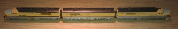
The kit, as shown below, has several parts printed in two different materials.  All the high detail parts can be printed in Shapeways Frosted Detail or Frosted Ultra Detail materials.  The low detail parts such as the chassis are printed in Shapeways White Strong & Flexible material.  When the kit arrives from Shapeways the headlights are attached to the loop that joins the ladders together; in the image below I have cut the loop and removed the ladders.

HO UP Tender Parts

The first thing to do is to work out how to collect power from the rails and get it into the body of the tender.  To do this I am going to use metal wheels with axle wipers.  One truck will collect power from the left rail, the other will collect from the right rail.

The trucks that come with the kit, as pictured below, are designed to take Proto 2000 33″ metal wheels from Walthers.  The trucks are fixed to the chassis with 3D printed bolster pins that simply push in.

HO UP Tender Power Pickup 1

Although the Proto 2000 wheel sets have metal wheels the axle is made from plastic which is no use for picking up power.  A good alternative are Intermountain’s 33″ wheel sets.  These have metal wheels and a metal axle and one of the wheels is electrically isolated from the axle.  However using these does cause a problem.  The point to point dimension of the Intermountain wheel sets is slighty smaller than the Proto 2000 ones.  This means that the wheel sets will fall out when the tender is picked up.  To solve this I have used small off cuts of solid copper wire superglued into the V grove below the axle sockets as pictured below.  When the trucks are the right way up and sat on the track the wheel set axles will be resting against the top of the axle socket; the copper wire simply stops them from falling out.

HO UP Tender Power Pickup 2

The next issue is how to transfer the power from the axle wipers up into the tender.  A flexible wire is the easiest way but the position of the wire can cause complications.  The further away from the bolster pin the wire is the more it will rotate as the tender runs around a bend. A crescent shape will need to be cut into the chassis to receive the wire.  The maximum radius that the tender will be able to negotiate will depend on the size of the crescent.  An alternative to this is to run the flexible wire up through the bolster pin.  Because the HO kit is a scaled up version of the N Scale kit the bolster pins are quite big.

HO UP Tender Power Pickup 3

I used a small drill bit in a pin vice to drill a pilot hole through the bolster pin.  The head of the bolster pin was printed with a hole through the thicker section to reduce material, which helps guide the drill through squarely.

HO UP Tender Power Pickup 4

Then I fitted the bolster pins into the chassis and used the larger drill bit to drill all the way through.  The size of the drill bit depends on the wire and wants to be just a bit bigger to allow the wire to pass through easily.HO UP Tender Power Pickup 5

The bolster pins were then removed and any swarf was removed from the holes.

HO UP Tender Power Pickup 6

Next come the fitting of the wheel sets.  It is very important to note their orientation.  In the image below the wheel set on the left is electrically connected to the wheel at the top.  The wheel set on the right is electrically connected to the wheel at the bottom, you can see the plastic isolator where the top wheel joins the axle.

HO UP Tender Power Pickup 7

It is important to get all the axles in the same truck orientated the same way around. otherwise the truck will cause an electrical short.  Because the trucks are the same, just rotated 180° you can insert the wheel sets the same way round in both, then when they are fitted to the tender one will pick up on one rail and one will pick up in the other.HO UP Tender Power Pickup 8

The trucks can now be fitted to the chassis as shown below.

HO UP Tender Power Pickup 9

Doing a rolling test at this stage is a good idea to ensure the wheels run freely.

HO UP Tender Power Pickup 10

To make the axle wipers I have used 1mm wide phosphor bronze strips about 45mm (1.771″) long.

HO UP Tender Power Pickup 11

The wiper strip is pushed through the axles.  It goes under the two outer axles and on top of the middle one.  That way it will utilize all three axles to collect power.

HO UP Tender Power Pickup 12

Then using my fingers I bent the ends of the wiper strip around the outer axles.  This will stop the strip from rolling out and moving as I work on it..

HO UP Tender Power Pickup 13

Using my soldering iron I tinned up the strip just above the hole in the bolster pin.

HO UP Tender Power Pickup 14

Then one of the wires from the DCC decoder was fed through the chassis and bolster pin.  A small section at the end of the wire was striped back and tinned with solder.  The end was then bent over by 90°.  In the image below this has been done to the black wire.

HO UP Tender Power Pickup 15

This hook can then be positioned over the tinned wiper strip and with a quick touch of the soldering iron they can be joined.

HO UP Tender Power Pickup 16 HO UP Tender Power Pickup 17

There is a risk with this configuration that the axle wiper will rotate and run diagonally across the axles.  If the wiper strip touched a wheel that is isolated from the axle it will cause a short.  There are two things that can be done to prevent this.

The first is to remove one of the end wheel sets, this will cause the wiper strip to fall out.  If you gently roll the ends of the wiper strip around a bit further between your fingers and then refit the wheel set not only will it be a tighter fit almost preventing the wiper strip from going diagonally, it should also improve the contact with the axles thereby improving the power pickup.  This can add drag to the wheel sets and you should check that the tender still rolls well once this has been done.

The second is to add a guide which the wiper strip will run between.  To do this I used some of the same solid copper wire I used in the V slots of the trucks.  I bent the wire into the shape shown below.HO UP Tender Power Pickup 18

This bent wire shape fits down through the second hole in the truck frame as shown below.  Once I was happy with the fit they were superglued in place .

HO UP Tender Power Pickup 19

The forked ends protrude down on either side of the wiper strip giving some room to move but preventing it from going diagonal.  The other end is held in place by the wire coming through the bolster pin.HO UP Tender Power Pickup 20

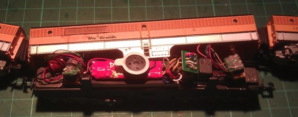
Below is a close up of a finished truck with a fixed axle wiper collecting power from all three axles.

HO UP Tender Power Pickup 21

This now completes the tender chassis, in next week’s post I will show you how the working tender headlights were fitted and how the tenders were finished.

Discovering the Possibilities of Etched Brass Part 3

Following on from last week’s post, where I showed you the first two sets in my new ‘Additions’ series of etched brass details, I promised to share with you some photos to demonstrate how effective the ‘Additions’ details really are. So in this week’s post I have some of the current work-in-progress photos for you.

So far we have only been working with the EMD DD35 Additions set; the weather here in the UK has been unusually fantastic so we’ve been making the most of it!

The DD35 set, pictured below, comprises of two long handrails for the sides and four corner handrails that need to be rolled into shape as I showed you in last week’s post.

DD35 Additions Set

DD35 Additions 1

DD35 Additions Parts

Below are some photos of a DD35 using the stock 3D printed handrails which will still be provided with the kits should you wish to use them and I think they work well when using the DD35 with a Con-Cor U50 as the stock handrail sizes match.

DD35 & U50 1

DD35 2

Having already cut out a set of Additions for a DD35 and having a new one under construction it was simply a matter of glueing them on.  They were a good fit using the same mounting locations on the side of the shell as the 3D printed rails and, as you can see below, they look very realistic.  They still need the final coat of paint to finish the model but I think the brass Additions really finish it off nicely.

EMD DD35 With Brass Etched Additions 1 EMD DD35 With Brass Etched Additions 3

EMD DD35 With Brass Etched Additions 5

Once complete I will have some more photos of this model to share with you as well as some of the Baldwin DT6-6-2000 with its brass Additions.

In the meantime, if you would like to purchase one of these brass Additions kits please drop me a message using the Contact page.

Discovering the Possibilities of Etched Brass Part 2

A few weeks ago I shared with you my designs for etched brass handrails and details to improve my Baldwin DT6-6-2000 and EMD DD35 locomotive shells.  These etched brass sets are the first in my ‘Additions’ series which will be available for all my locomotive shells.  Now that the first batch have arrived I wanted to share some of the results with you.

DT6-6-2000 Additions Set

DD35 Additions Set

The sets pictured above are etched from a sheet of 0.2mm or 8 thou brass and this has given me the ability to make handrails the correct actual scale size.  Although the brass is very thin I recommend using a very sharp, if not new blade in a craft knife to cut the parts out because pressure applied to remove them with a blunt blade will distort the parts.

The parts have small tabs which are only half thickness showing you where to cut them out, and making it easer to cut.  Depending on how close to the part you can make the cut it is likely there will be a small bur which can easily be removed by carefully filing the area with a flat needle file.  I found the best way to handle the parts was with a set of tweezers with a flat end.  Even between my fingers I could see the parts had the potential to bend out of shape. Below is one of each part from the DT6-6-2000 set.

DT6-6-2000 Additions Parts

The center leg of the end handrails, shown in the center above, is designed to be bent to form a dog leg as shown below. At the bend line the brass has again been etched to half thickness to mark the bend and make it easer to do.  I used my flat end tweezers to grip the brass at the bend line and pushed it over with my fingers.

DT6-6-2000 Addtions End Handrail

The sun visors for the DT6-6-2000 also have two stay bars that are designed to be bent back as shown below.  This again was done simply with the tweezers and there is an etched section at the bend point.

DT6-6-2000 Addtions Sun Visor

This can then be glued directly above the window as shown below on a different locomotive.

DT6-6-2000 Additions Sun Visor 2

These particular sets only have additional etched details on one side, for example the real DD35 handrail stanchions, as pictured below, are made from a folded plate made into a channel section.

EMD DD35 Handrail stanchion

To accurately model this detail I etched the middle of the stanchion to give a fluted effect as shown in the 3D rendered image and photos below.

DD35 Handrails Additions Close Up Render

DD35 Additions 1

DD35 Additions Close Up 1The small handrail sections shown above are for the ends of the DD35 and there is one for each corner.  Once they have been carefully cut out as shown below, again using the half thickness brass as a guide, they need to be shaped.

DD35 Additions Parts

To shape the end rails I rolled the brass handrail around the handle of a watch mender’s screwdriver handle which had the radius I was looking for.  As you can see from the results below the handrail section is now ready to be fixed to a DD35 Shell.

DD35 Additions End Rail 1 DD35 Additions End Rail 2

The ‘Additions’ series are designed to complement my range of 3D printed locomotive shells, enabling you to model in finer detail to suit your budget, and in a later post I’ll show you how effective the ‘Additions’ details really are.

In the meantime, if you would like to purchase one of these brass Additions kits please drop me a message using the Contact page.


Discovering the Possibilities of Etched Brass

With two locomotive shells already available to buy and several more in the pipeline I have started to look at what can be done to develop them further.  The most frequent request I have had from customers has been for brass handrails so in this post I want to share with you how I’m working on that.

3D printing offers many advantages over other forms of modeling; one of them is the level of detail which can be achieved.  My current locomotive shells and parts have been designed to be printed with a detail level of 0.1mm which for parts such as small vents and door handles is perfect.  But when it comes to self-supporting items, such as handrails, they need to be thicker in order to survive the print and handling process.  Typically a wire part such as a handrail has to be at least 0.8mm in diameter.  Now I know that doesn’t sound a lot but in N scale at 1:160 that is equivalent to 128mm which is very big, and although it is passable, compared to injection molded or wire handrails on a lot of the new ready to run models, it is huge.

The 3D printed handrails on the EMD DD35 pictured below are clearly much larger than the injection molded ones on the Atlas C-628 model pictured underneath.

Locomotive Shells

Atlas C-628 1

The answer lies in brass etching.  Referred to as acid-etching, resist-etching and photo-etching, it’s a process of removing metal in varying layers around a design, leaving behind the composite parts of the model. The main advantage to this is we are dealing with metal which allows it to be incredibly thin and detailed.  The brass metal sheet which I will be working with is only 0.2mm thick and I can etch out parts that are only 0.24mm wide.  This is ideal because I can model handrails at actual scale size.  Although the parts are etched from a flat sheet, once the handrails are painted their ‘squareness’ will be smoothed out.  They can be also designed to be bent in the correct places to achieve the shapes we need.

To begin with I looked at the handrails for the Baldwin DT6-6-2000. There are four side rails and two end rails on this locomotive and I needed to find an efficient and cost-effective way to lay them out so they didn’t take up too much room on the sheet but still had enough metal around them for support.  At this point I realised there would be some spare space on each handrail set so I looked again at the DT6-6-2000 to see what else I could add.  Looking at the photos of the original locomotives working up and down the country I noticed a lot of them had sun shades over the cab windows.  So I have included a set of sun shades with each set of handrails.  Below is the rendered image.

Baldwin DT6-6-2000 Additions Render

I’ve also designed a set of handrails for my EMD DD35 model as pictured below and will be making this set available soon.  The set includes the two main side rails and the four corner rails, there are no sun shades with this locomotive as it has no cab!

EMD DD35 Additions Render

The corner rails also shown below will be etched flat and once removed from the sheet can be bent to form the correct shape.

DD35 Handrails Additions Close Up Render

As you can see from the images above the brass etched parts will form part of my new ‘Additions’ series, which will be available alongside my established range of Shapeways products soon. You’ll have the choice to buy the complete locomotive kit from Shapeways and then if you choose you can add further detail by using the Additions products which will be available direct from this site. I’m striving to make both options as affordable as possible, and at the same time giving you a working, detailed locomotive model to suit your budget and modeling choice.

If you’re interested in being the first to try these brass etched details drop me a message through the Contacts page, I look forward to seeing these in action!

Making your own DCC plugs and connectors

With a lot of DCC installations, particularly on older locomotives, the wires and plugs need to be modified in order to make them fit.  This often creates weak wire joints, especially in areas where the wires can move, so I wanted to find a way to protect these areas.

Recently I have been installing single DCC decoders in multiple locomotive consists; below is a set of Con-Cor Alco PA/PB units.

Con-Cor DRGW PA-PB-PA

Both the PA (Cab units) are powered and the PB (Cabless booster) is a dummy.  Inside the PB I have installed a Digitrax sound decoder with the wires running through the corridor connections to the two motors, similar to the Con-Cor EMD E7 DCC installation from my previous post.

I decided to add connectors into the system so I could separate the units if required, which also made it easier to trace any faults such as short circuits whilst testing the units.  Below is an image of the wire harness before it was fitted into the PB unit.  The bit in the middle is a socket for the DCC decoder with a homemade plug fitted into it which joins all the wires together for DC operation and testing.

PA Wire Harnes

Although the wires are soldered to the pins, they are still delicate and given the limited number of strands, individually the wires could easily be broken off.  To prevent this from happening, after I had tested the harness I painted the soldered connections and wire ends with a PVA glue. I used a cheap PVA designed for school projects from a local art shop. The PVA went on well and as it went tacky it held in all the pockets between the wires.

PVA Socket

I also added a second coat a few hours later to ensure I had good coverage.  Once dried it went clear and held all the wires in place, plus it gave them a coating to prevent any shorting.  I also did the same thing with the plug ends.

PVA Plug

Once everything is assembled the PA units can be separated from the PB unit by simply pulling the plug without risking damage to the soldered wires at their weakest point.

Con-Co PA-PB with Sound

Another advantage of this is a second PB dummy unit (or possibly a powered unit) could be added into the consist as long as it had the same wires and plugs running through it.

Here is as short video of the D&RGW Prospector pulling into Solent Summit station.

Sadly the sound decoder speaker is not as loud as the noise from the older Con-Cor motors which drowned it out, but that is a challenge for another post.

Cost-effective DCC installs for consisted locomotives

With Digital Command Control becoming ever more popular more clubs and home layouts are switching to it, but it can be quite costly to convert all your locomotives to DCC, so I’ve been looking at ways to make this cheaper.

A lot of US outline trains run with several powered units forming one consist and using one DCC decoder for the whole consist is my plan.   A good example of this is the set of powered EMD E7 units below.

IMAG0242

These models, made by Con-Cor, will always be run as a set and although the middle unit is a dummy locomotive the other two would normally both require a DCC decoder.  This is because there’s no electrical connection between the three units and, despite both being good runners, the two powered units run at different speeds.   This is a problem because one locomotive will always be pushing or pulling harder than the other.

Below is a video of the two powered units (without their shells) on a DC test track.

Clearly you can see that the nearest locomotive runs much faster than the other.  This is because the motor in the nearest locomotive has a much lower starting voltage.  If both locomotives had their own DDC decoder fitted they could be speed matched.  This is done by adjusting the DCC configuration variables using a DDC controller or a system plugged into a computer.  Doing this effectively alters the starting voltage of one or both of the locomotives to make them run at the same speed.  The drawback of this is that you would still need two decoders, an understanding of how to do this, and, if the train is run on a DC layout, the problem would still be there as the CV settings do not have any affect under DC control.

An alternative is to increase the starting voltage of the faster locomotive motor.  An easy way to do this is to add some resistance into the electrical circuit, but this can cause other problems as resisters do this by turning the unwanted power into heat.

A better way is to add a diode into one of the motor feeds.  A diode works by only allowing DC power to flow in one direction whilst causing about a 1.5 volt drop.  Of course this would mean the motor could only run in one direction so a second diode will also need to be used at the same location but positioned in the other direction.  This meas that the power going to the motor will always pass through a diode irrelevant of the direction of the locomotive but with a reduced voltage.

Depending on the speed difference you have between the two locomotives, you may need to use more diodes to give a bigger voltage drop.  For this particular pair of locomotives three diodes, giving a voltage drop of 4.5v, were required in order to make the two motors run at the same speeds.  There is room between the main chassis and the shell so I constructed the diode circuit to fit in this space using 6 diodes; three for each direction.

Diodes E7 Chassis E7 Chassis With Diodes

E7 Chassis Ready For Shell

With the diode circuit fitted into one of the motor feeds you can see the difference in this video, also on a DC test track.

Now the two power units run at the same speed I can use one DCC decoder to power both motors.  It is important to select a decoder that has a maximum current capacity that is more than the combined current draw of the two motors.  This can easy be checked with an amp meter.  With the shell removed from your locomotive, connect a DC controller to your locomotive, passing one of the motor feeds through the amp meter.  Then using your fingers, prevent the motor from turning and turn on the controller.  The motor will try to turn but will stall as you have it clamped in your fingers, and the amp meter will measure the maximum current drawn by the motor.  Do this with both motors and add the values together.  If the combined value is less that the maximum current capacity of your chosen decoder then it will be ok.

As there’s lots of space inside the dummy unit the DCC decoder is installed in there.  I used a Digitrax decoder and ran the wires through the corridor connections.  This causes a small problem in that the three locomotives are now permanently fixed together by wires; should they come uncoupled it could put too much strain on the wires and cause damage.  To solve this the couplings have been replaced with 3D printed permanent couplings.

Fixed Coupling 1

These have the same ends as Rapido-style couplings and are a direct replacement using the same spring.  A flexible corridor connection was also made using black foam and corrugated card.

E7 Coupling 1 E7 Coupling 2

The chassis for the dummy unit is actually a different make, Life-Like, but this is a bonus because it has power pickup on the trucks.  All three units have power pickups that can now be connected together which greatly improves the performance of the combined locomotives.  So this three unit EMD E7 set is now DCC converted using only one DCC decoder.  Here they are pulling ‘The City Of Los Angeles’ on the GAMRG’s layout at the 2014 NMRA winter meet in Benson, UK.

Hopefully this will save you money on upgrading your locomotives to DCC, which can become incredibly costly given some size layouts and train collections. I’ve been experimenting in a similar way with a sound decoder; if I make any notable progress I’ll post it here.