Improving Peco Points for DCC Operation

In this week’s post I will show you how I modify Peco points or turnouts to use with DCC, and explain why I make the changes.

Peco make a variety of points in all the common scales and I have used them for many years.  Personally, having used them for American and British trains in both N and OO scales, I think they are the best ready-to-run points available.  However I always make modifications to them rather than use them directly out of the packet.  You can use them directly from the packet and they will work just fine, but I find for lasting reliability a few improvements are needed.  For my example I am using some brand new OO/HO large radius points as shown bellow.

Peco Points DCC Conversion 1

This point, as it states on the packet, is an Electrofrog.  This means that the area where the rails cross, commonly called the frog, is metal, allowing the maximum amount of electrical connection with the pickup wheels of your trains.  Peco’s other points are called Insulfrog and these have a plastic frog. Insulfrogs are the easiest to install because the plastic frog isolates all the rails so you don’t have to make any electrical brakes in the track or do any special electrics. But the downside is the large electrically ‘dead’ section over the plastic frog which can cause stalls with slow-moving or small trains.  So I always use Electrofrog points.

To use the point shown below all you need to do is connect the two inner rails using a plastic rail joiner.

Peco Points DCC Conversion 2

Below is an extract from the back of the Peco packet showing how to wire this up for DC or DCC power.  With DC power if you don’t include the isolating rail joiner the point will also switch the power on and off in the two sidings.  It does this by making the polarity of the rail connected to the frog the same as the stock rail (outside rail) for the route that is not selected.

Peco Points DCC Conversion 2-1

As I said before, using this point directly out of the packet and connecting it as shown above should work just fine but the drawback is how the power is delivered to the frog.

As supplied, the frog relies on electricity travelling from the stock rail into the point blade via the contact of the two surfaces.  Then it travels up the blade rail to the frog.  When the point is changed the other point blade makes contact with the other stock rail and the power is fed from that side, also reversing the polarity of the frog.  The point throw bar has a built-in spring which keeps pressure on the point blade, holding it against the stock rail.  When the track is new and shiny this is fine, but over time dust and grime will get inbetween the two and the electrical connection will become weaker.  And if you weather and ballast your track this connection will probably stop working altogether.  It can be cleaned by using a piece of fine sand paper or a file but this is not an ideal solution or a permanent fix.  Plus the point blade can easily be bent and it’s next to impossible to get it back to straight again.

There is also another problem that can occur.  Electricity will always follow the path of least resistance.  For example if you had a bit of track with two power connections and one was badly soldered, although you can’t tell, the electricity would flow through the good connection.

So imagine you had a point connected as described above with dirt or dust inbetween the point blade and the stock rail; it’s just about working and the locos will travel over it.  But the train you are pulling has a coach with a light in it powered from the track and there are pick-ups on all wheels of the coach.  As the coach spans the point blade, i.e with one truck or bogie on the stock rails and one on the frog the electricity will elect to travel through the coach and not through the points.  If the lighting circuit in the coach is only a 1.3v LED with a tiny current draw it will not be designed for a lot of power and there is a chance that it will blow.  This could happen as the full voltage being pulled by the loco is now passing thought the coach circuit.  With a DCC powered layout it may also have the current from several locos running through the coach and I have seen a coach that was parked across such a point that got so hot that the truck actually melted.

So now you know why I modify the points, but what do I actually do?

The first step is to decide how else you can power the frog because it needs to be fed from one stock rail or the other, depending on the direction it’s set in.  This can be done in a variety of ways.  Peco make an accessory switch that can be fitted to their point motors to power the frog.  Seep point motors and Tortoise slow motion point motors both have a built-in switche that can be connect directly to the frog.  Peco also make an electronic switch called a smart frog, this will only work with DCC.  The smart frog is connected to the power bus and the frog. As a train wheel makes contact with the frog, if the polarity is wrong, it will detect a short faster than the DCC control system and reverse the polarity, allowing the train to continue as if nothing was wrong. Other companies like Tam Valley make the Frog Juicer which works in a similar way to the Peco smart frog.

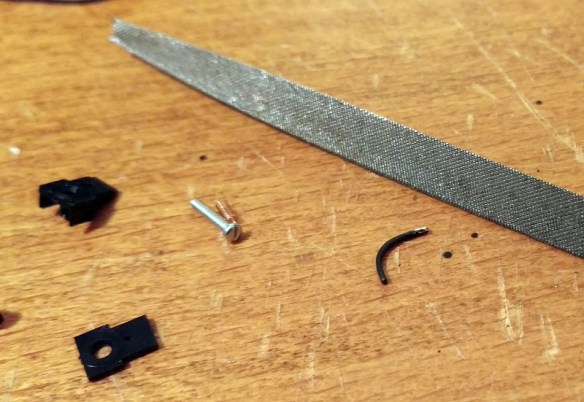
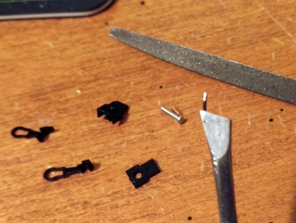
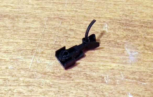
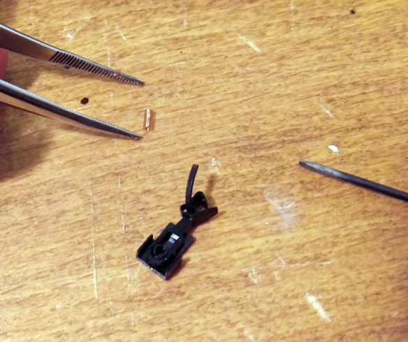
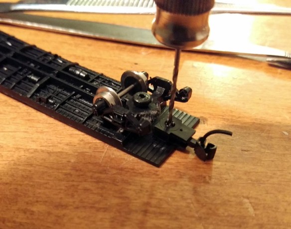
Simply feeding the frog will greatly improve the performance of the point because the power will run up into the frog and back down the point blades but there’s still an issue.  The point blade that’s not touching a stock rail will be a different polarity, as both point blades and the frog are all the same, and there’s the possibility with wide flanged rolling stock that a short could happen as a train passes by.  To overcome this Peco have given access to the connecting wires on the underside of the point.  In the picture below you can see two small slots in the plastic, each with a connecting wire in.  These wires join the frog to the point blades. I remove these wires; as they have been spot welded in the factory you can simply put a small flat ended screwdriver into the slot next to the wire joint and twist.  The spot weld will break, repeat for the other end and the wire will fall out.

Peco Points DCC Conversion 3 
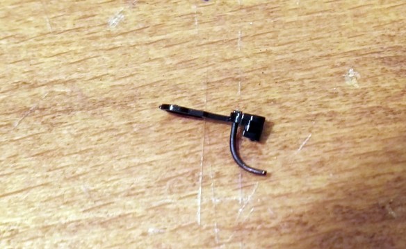
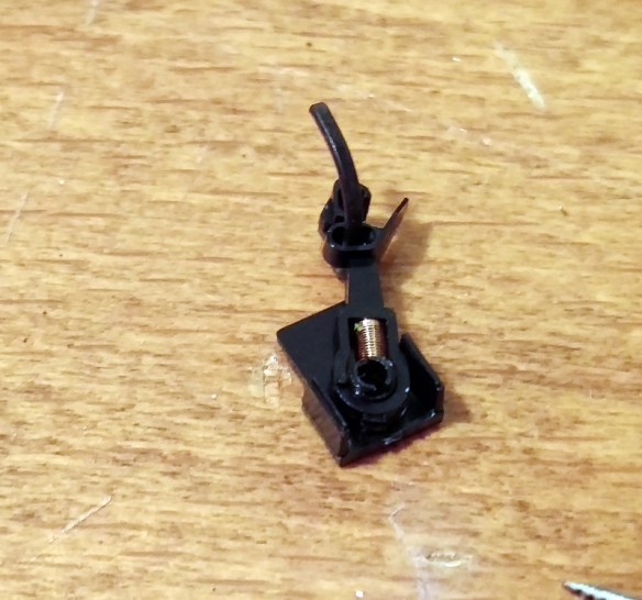
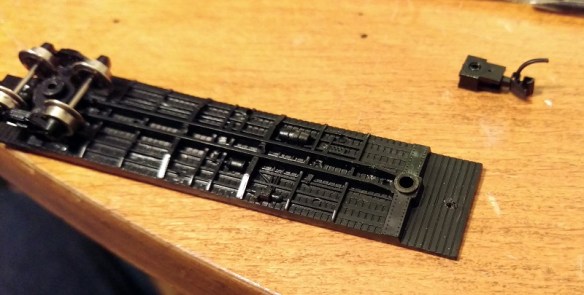
The problem now is the point blades are again reliant on the contact with the stock rail, however Peco have made this easy to fix.  As you can see in the image below, next to the slots where we removed the connecting wire, they have omitted some of the plastic allowing access to the underside of the stock rails and the top of the point blades.  On older points this access is not there but can easily be made with a sharp knife.

Peco Points DCC Conversion 5

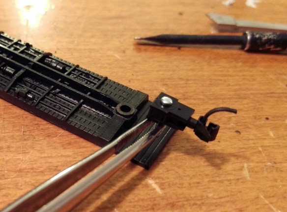
Using a soldering iron I tinned the underside of the rails with solder.

Peco Points DCC Conversion 6

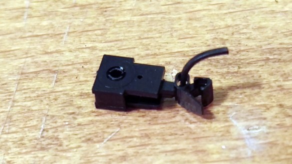
I then stripped the insulation off some solid core wire and cut it into strips, the same length as the distance between the stock rail and nearest point blade.

Peco Points DCC Conversion 7

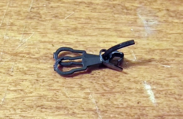
Then I placed the wire over the gaps and used the soldering iron to attach each end to the tinned area.

Peco Points DCC Conversion 8

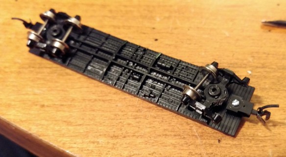
Repeating this on both sides means that the point blades are permanently connected to the stock rails.

Peco Points DCC Conversion 9

And there you go; the point is ready to be installed on the layout.  There’s no danger of a bad connection to the point blades, or a short between the free point blade and the stock rail and the frog is powered via a switch.  This point will be electrically reliable even when weathered and ballasted .

Peco Points DCC Conversion 10

So although Peco points work straight from the packet, in my experience making these improvements up front will make your layout more reliable and keep your trains running well for years.

Converting An N Scale Bachmann F7 to DCC

The N Scale Bachmann F7 has had three revisions to date and the most recent one, made available in 2013, is supplied with DCC.  But what about the first two?  In this post I will show you how I add DCC to the locomotives in a cost-effective way.

The Bachamm F7 over all is not a bad locomotive; it has great polling power and the body work, although not as good as the Intermountain model, is nice.  They do tend to run a bit noisily so installing a sound decoder for me was not an option. As I have several of these, installing a basic decoder in each starts to add up, so again I am going to use one decoder to power two locomotives.  When doing this it is important that the locomotives run at similar speeds when used together on DC power.  Luckily these do, but if yours don’t I have already covered a topic like this and you can read about it here.

Bacmann F7 DCC Install 34

The F7 A & B set I am converting to DCC, as shown above, is the second version but both first ‘Plus’ version and the second ‘Spectrum’ version are very similar in chassis shape and design so this method will work for both.  You can read about the difference in Spookshows N Scale encyclopedia here.

With the shells removed, as you can see below, both the A and B units are exactly the same with the exception of the A unit having a light bulb pushed into the hole at the front.  To remove the shells simply spread them at the fuel tank and they will un clip then lift off.  You will also see that the chassis totally fills the A unit shell leaving no room for a DCC decoder to be installed.  But because the B unit has the same chassis there is space in the B unit where the cab would have been so I will be putting my decoder there.

Bacmann F7 DCC Install 1

There are no wires inside the chassis, which is split into two, and the light bulb simply picks up power by touching the chassis halves.  A down side to this when running on DC is the light comes on in reverse as well.  And for DCC,  the motor picks up its power in the same way so we will need to isolate it.

To take the chassis apart is fairly simple.  First remove the fuel tank by undoing the screw in the middle.

Bacmann F7 DCC Install 2

Then undo the two chassis screws in the left half and it will lift off.

Bacmann F7 DCC Install 3

Turning the left half over you will see a spring projecting out of the chassis.  This is the bottom motor contact that connects the left half to the motor.  This spring needs to be removed simply by pulling it out.

Bacmann F7 DCC Install 4

With the two halves separated the whole assembly will come apart.  The motor simply lifts out and the truck assemblies will already be free.

Bacmann F7 DCC Install 5

The right half of the chassis has a stub that sticks out and connects to the top motor contact.

Bacmann F7 DCC Install 37

This stub needs to be removed.  This can done with a good pair of large side snips and a file.  The chassis is made from a fairly soft metal so it files down quickly.  In the photo above you will also see the inside of the black tape that has been put across the holes in the chassis. I believe Bachamnn added this to the second version to prevent particles getting into the motor winding.  Also as it is sticky on the inside it will catch any particles thrown off the motor brushes.  You can see some of those just below the stub. Filling the stub will create metal fillings which you also don’t want to get in your motor so once the stub has gone remove the black tape and clean the chassis half to remove all the filings.  A stiff brush will normaly do this.

With the chassis half clean, you can do a test fit with the motor to make sure the motor contacts to not touch the chassis.

Bacmann F7 DCC Install 6

To do a proper test the chassis can be resembled with just the motor in it and you can do a continuity test with a volt meter.  Dont forget to put the little plastic spacers back in, there is one for each screw and one in the fuel tank.

Bacmann F7 DCC Install 7

Next we need to create a path for the bottom motor wire.  As there is no room inside, the wire will have to come up the outside of the chassis but as the shell is a snug fit around the motor, there is still no room.

Bacmann F7 DCC Install 8

So in order to make room I have filled a V grove up the side of the right chassis half.

Bacmann F7 DCC Install 9

The grove also continues round under the fuel tank.  The grove needs to be just big enough to take the wire you are using so the face of the chassis and wire will be flush.

Bacmann F7 DCC Install 10

Once any metal fillings have been removed the chassis is now ready and we can turn our attention to the motor.  The motor body is already isolated from the contacts so all we need to do is add our wires to the contacts.  Although we can change this later it is useful to add the right wires onto the motor now so we know which is the positive side.  Normally orange is the positive motor wire and gray is the negative.  But there is no indication on the motor as to which is which.  On my work bench I have a DC controller with a test track and a pair of wires.  When a train is running forwards and to the left the right rail is my positive, colored red, and the left is my negative, colored back.  Touching the red and black wires onto the contacts will make the motor spin and in the configuration shown below you want the motor to spin anticlockwise.  That would be the same as forwards to the left.

Bacmann F7 DCC Install 11

To add the wires I quickly heat the contacts with the soldering iron, for one to two seconds, then add a little bit of solder just to tin the contact. You don’t want to over heat the contact is it is a perfect conductor of heat and there are plastic parts inside. Next I tin the end of my wire, hold it to the contact and quickly touch it with the iron.  The two tinned areas fuse and you have a good connection.  Note the wires need to be long enough to run up inside the locomotive and across to the B unit.

Bacmann F7 DCC Install 12

Before re-assembling the chassis I also change the couplings on the loco.   When these where being run under DC I used Unimate couplings from Red Caboose.  These provide a nice close couple that will not come undone on the track however as I will now have wires running between my locos I don’t want them to come uncoupled at all.  To do this I will replace the Unimates between the A and B unit with one of my fixed link couplings.

In the image below you can see the underside of the Bachamnn power truck.  Just to the right of the tuck and before the coupling box are a pair of pins that can be squeezed together with a pair of needle nose tweezers.  This will cause the coupler box to pop off.

Bacmann F7 DCC Install 13

Inside the coupler box is a spring that fixes over the peg on the back of the coupler.

Bacmann F7 DCC Install 14

My 3D printed fixed coupler is a direct replacement for the old Rapido style couplers so drops right into the Bachmann coupler box.

Bacmann F7 DCC Install 15

For now I only fixed one truck to the fixed link but you could do two, one from the A unit and one from the B unit, at this point.

Bacmann F7 DCC Install 16

Now the chassis can be reassembled.  Note the wire form the bottom motor contact is coming out the bottom of the chassis in front of the plastic spacer. (I know the wire is brown and not gray but I have run out of gray!).  Also when you refit the tracks make sure the metal contact for power pickup is rubbing against the underside of the chassis not the inside as this will prevent the trucks from rotating.

Bacmann F7 DCC Install 17

The brown wire (bottom motor connection) can now be placed in V grove that was filed earlier and the fuel tank can be replaced.  Also I have put some Kapton Tape over the holes in the chassis to replace the black tape I removed, this also holds the wire in place.

Bacmann F7 DCC Install 18

Now the motor is isolated and wired up the next two wires are the power supply.  On top of the chassis are four nubs that the shell sits onto.  Interstingly these are slightly narrower on the bottom than they are on the top so all I do is wrap the end if my wire around the base of the nub a full 180° and solder it in place.  I have yet to have one of these fail.  And as long as there is nothing sticking up above the top of the nub the shell will still fit.  The red wire goes to the right side and the black, or purple in my case, goes to the left.  I must order some more different colored wire!

Bacmann F7 DCC Install 23

The last wires, for the A unit, are for the light.  The standard light is a light bulb and these can be power-hungry and get hot.  So I replace mine with warm white LEDs. Below is a comparison with standard 3mm LED on the right and a 1.8mm LED on the left which I will be using.

Bacmann F7 DCC Install 19

As all LEDs need a resistor in line I make the resistor a part of the headlight by folding one of the resistor legs back onto its self and soldering it to the LED.

Bacmann F7 DCC Install 20

Then I wrap it all in Kapton Tape to prevent it shorting.

Bacmann F7 DCC Install 21

Finally I trim back the legs ready to solder on the wires.

Bacmann F7 DCC Install 22

The LED will sit in the same place as the light bulb.  To protect against shorts I put a strip of Kapton Tape over the nose then cut out the hole with a sharp knife.

Bacmann F7 DCC Install 24

The LED light assembly then pushes into the hole and the legs, sitting on top of the Kapton Tape, can be soldered too.  As LEDs only work in one direction it is important to know which is the positive and negative.  The blue wire, matching the decoder, is the positive.

Bacmann F7 DCC Install 25

With all the wires in place they can now be taped down with Kapton Tape so they are tidy and clear of the shell.  Check to make sure the trucks rotate freely.

Bacmann F7 DCC Install 26

To fit the shell I you could simply run the wires through the window in the connecting door at the back but this can be really tricky so using a sharp knife I simply remove the plastic under the window.

Bacmann F7 DCC Install 27

This allows the shell to be lowered onto the chassis without pulling or pushing on the wires.

Bacmann F7 DCC Install 28

When it comes to the B unit I do exactly the same, except the wires run to the front and there is no light.

Bacmann F7 DCC Install 29

To join all the wires up I like to uses little bits of cooper strip board.

Bacmann F7 DCC Install 30

These are then superglued to the nose of the B unit.  You could use one piece and glue it to both sides of the chassis but this would mean the unit could not be taken apart for repair if needed.  You also need to make sure the DCC decoder will fit behind the cooper strip boards and they do not protrude out side of the chassis so the shell will still fit.

Bacmann F7 DCC Install 31

Once you are happy with the placement of the cooper strip board, solder the wires together, orange to orange etc. The red and purple (black) can go directly onto the B unit chassis.  At this stage there are a few checks that you should make.  First, using a volt meter set to a continuity check, check that the left B unit chassis is connected to the left A Unit chassis, and repeat for the right.  Secondly check that the left and right chassis are not connected to each other.  Thirdly check that none of the chassis are connected to any of the cooper strip board terminals.  Then using 12v DC wires from a controller test that both motors are running the same direction when you connect them to the orange and brown (gray) wires and finally test the headlight works when you connect the 12v DC wires to the blue and white wires.

Bacmann F7 DCC Install 32

I also connected the fixed link coupler to the front truck of the B unit at this stage.

The last stage is to solder the six decoder wires to the copper strip board terminals and chassis points.  I have used a Digitrax DN163, it was a bit of a tight fit because this decoder has a plug on it making it thicker than normal but most N or Z scale decoders will fit.

Bacmann F7 DCC Install 33

I cut the front door of the B unit shell to fit over the wires the same as I did with the A unit and fitted it onto the chassis.  And there you go; two powered locomotives connected with a draw bar, which is prototypical, and one decoder.

Bacmann F7 DCC Install 35

But there is one more thing that you can do to make this even better and that is to have four locomotives with two decoders.

Bacmann F7 DCC Install 36 Normally the locomotives would all have different numbers but to make things easy I have configured the two DCC decoders to be both the same address and switched the rear pair to run in reverse as their forward direction.  This means you don’t have to consist the locomotives, and they won’t take up two slots in your DCC command station. This can all be done by changing the configuration variables or CV values; which can be fairly in-depth subject so it is something I will cover in a later post.

Re-powering A Dapol Semaphore Signal

Recently I have been working on a British outline OO layout which had some working semaphore signals.  Sadly some of these signals had suffered some electrical damage which rendered their control circuit boards inoperative. In this post I will be sharing with you a few simple methods of repairing Dapol semaphore signals.

The Dapol semaphores, as shown below, are nice looking signals and have a fairly basic drive system which is self contained in the tube below the signal.  Above ground there is a nicely detailed rectangular post with the rotating arm on top.  The arm is connected via a crank to a push-rod that runs down behind the post.  You will be able to see this in some later photos.  The glass lenses in the end of the arm are transparent and a small LED shines through creating the correct color.

Dapol Signals 1

Below ground is where all the clever parts are.  Interestingly the drive system on these OO signals is also used for their N Scale signals; Dapol have simply changed the size of the signal on top.  In the large threaded tube at the bottom of the signal is a circuit board, electric motor, gear rack and worm gear.  After the large nut has been removed there is a tiny screw at the base of the signal which holds the two halves of the tube together.  Once that has been removed the tube can be separated.

Dapol Signals 2

The motor is in the left half and the circuit board is in the right.  You can also see the push-rod that runs up behind the signal pole in front of the ladder.  And if we zoom in you can see below the push-rod is a spring.  This spring is attached to the push-rod and when it’s moved up and down the signal arm moves up and down.

Dapol Signals 14

The two pairs of metal contacts are part of the circuit board; as the motor spins the worm gear it drives the rack either up or down pushing the rod.  A spigot sticking out of the rack touches one of the pairs of contacts creating a circuit and telling the circuit board that the rack is at the end of its travel.  However as the circuit board is damaged these are of no concern to us.

As new, the signals work by providing 16v AC power to the red and black wires.  This powers the circuit board and the LED at the top of the signal pole.  Then by simply touching the two yellow wires together, using a momentary Push-To-Make switch, the signal will change. Even when you let go of the switch the motor will keep going untill the rack gets to the end of its travel.

On the first of the two damaged signals only the motor drive function was inoperable, the light still worked when 16v AC power was applied, so the circuit board was still producing low voltage DC which is also needed to drive the motor.  In the picture below you can see the wire connections.  The red and blue are the DC feed to the motor.  The tiny red and, hard to see just above the yellow, tiny black are the LED feed that run up inside the signal pole.  The big red and black are the 16v AC power in and the yellows are the activators.

Dapol Signals 4

So to fix this signal I removed the motor wires from the circuit board and extended them by soldering on some more wire and heat shrinking the joint.

Dapol Signals 5

Then I removed the yellow activator wires from the circuit board and added a pair of wires to the LED feed connection points.

Dapol Signals 6

The signal was then reassembled with the new wires coming out of the bottom.

The next step was to take the low voltage DC power, coming from the new blue and green wires, out to the layout control panel. Then, using a momentary double pole double throw (DPDT) switch, return the power to the motor wires, in positive or negative, to make the motor go one way or the other. The DPDT switches I use are toggle switches as shown below.

Dapol Signals 16

These have six connections on the bottom.  When it is thrown one way it joins the middle pair to the top pair and the other way joins the middle pair to the bottom pair.

So, if the incoming low voltage DC power is connected to the bottom pair, then reversed and connected to the top pair, throwing the switch one way or the other will reverse the DC power.

Dapol Signals 15

The motor is then connected to the middle pair of terminals, not shown above, and the signal can be manually controlled. My apologies as I got a bit carried away with the work and so didn’t take any more photos of this particular signal.  As the switch is a momentary, when you let go it springs back to the middle and stops the motor.  There’s no danger of pushing the motor too far as when the rack gets to the end of its travel it simply stops, although the motor keeps spinning.  The spring on the end of the push-rod, and there is another one on the bottom of the rack, supply just enough pressure to make the rack re-engage with the worm gear when you want it to run the other way.

This fix, although functional, is not ideal as you are still relying on a damaged circuit board and all the small parts inside the tube.  Plus you have to hold the switch untill the signal has reached its position.

The second fix I have for these signals is a bit moire drastic but I think in the long run is a more durable solution.

The second signal’s motor and circuit board had failed so I removed all of the parts from inside the tube.  Sadly the LED had also blown on this particular signal so the wires for that will go as well.

Dapol Signals 7

As all the points on this layout are powered with Seep point motors it made sense to power the signal in the same way.  Seep make a special point motor with a latching spring which is designed to work with hand-built points that don’t have a latching spring of their own.  The latching spring means the motor will stay in the required position even though the spring on the push-rod will be pushing back.  This latching point motor was mounted to a ‘Tee’ shaped mount as shown below.

Dapol Signals 8

There is a slot for the motor throw bar to pass through and the large hole above the throw bar is for the signal tube.

Dapol Signals 9

You can see the latching spring under the motor cross-bar.

Dapol Signals 11

As the tube on the bottom of the signal was now empty it could be reduced in length; this was also necessary so it didn’t hit the throw bar.  The last thing to do was to connect the throw bar to the signal push-rod.  However there is a problem in that the point motor movement is more than the signal needs, and as the point motors are powered by Capacitor Discharge Units the motor bangs over very hard which will damage the signal.

To counteract this I made a very basic omega ring out of thin nickel rod.  One end was superglued into the spring on the bottom of the push-rod, the other was looped around the motor throw bar.

Dapol Signals 13

Although basic, this omega ring absorbs the sudden shock from the point motor as well as any extra movement while still supplying enough force to move the push-rod.  The two shorter tube halves were glued together and the ‘Tee’ mount was screwed to the underside of the layout.  The signal was then put though the hole in the layout and mount.  Before the large nut was tightened up the signal could be tilted to one side to alow the omega ring end to be slid over the point motor throw bar. Once tightened up the omega ring could not slide off the throw bar, but as an extra measure I glued a small washer onto the end of the rod.

This second fix was a lot better because the signal changed quickly with a single touch of the switch and any wiring is the same as a standard point motor.

These signals have also been modified in a similar way with servo motors which gave a very nice smooth action and this might be something I will try next time.  If I do I will share it with you.

Adding N Scale Wheelset Resistors for Circuit Detection

As well as 3D printed models I do a lot with DCC and model railroad wiring.  Recently I have been building computer controlled DCC layout and this adds a whole new level of requirements to the layout such as circuit detection.  In this post I will share with you how I get rolling stock ready for circuit detection on an N Scale DCC layout.

Circuit detection is fundamental to computer control as it tells the computer where trains are on the layout.  It is also useful if you have hidden sidings and you want to know where your trains are.  There are several companies that produce circuit boards for circuit detection and on this layout I have used Digitrax’s BDL168 boards.  The boards work by measuring a resistance across the track; this can be anything from an LED to a DCC chipped locomotive.  So if you have a locomotive in a section connected to a BDL168, even though it’s not moving, the board will detect a resistance and turn on the output for the section.  The output could be connected to a display panel or a computer could pick it up through the Digitrax Loconet system.

This is fine for locomotives and rolling stock with illumination but what about basic freight cars or wagons?  The computer controlled layout I’m building is a British outline model railway and has a lot of coaches that will all need to be modified so the circuit detection can pick them up.  A lot of the coaches, as shown below, are made by Graham Farish and luckily have metal wheels, obviously plastic wheels sets are no good for circuit detection..

Wheel Set Resistor 1

If you do have rolling stock with plastic wheels you can get replacement wheel sets for just about all ready-to-run stock.  Although metal wheels usually run better you don’t have to change all the wheel sets for metal ones, only the ones you intend to modify.  In fact you only need to modify one wheel set per item of rolling stock.  Because of the length of the coach I am going to modify one wheel set in each truck.  If it was a short wagon I would only do one.  Ideally I would like to modify the two outer wheel sets but as the axle is so close to the coupling box there would be no room.

Wheel Set Resistor 2

Adding lighting to the coach would be one way of creating a resistance across the coach but by far the simplest way is to add a resistor to a wheel set.

Wheel Set Resistor 13

As you can see from the images above with N Scale, and OO/HO, a standard resistor is a bit big and would be very impractical.

To overcome this, tiny resistors called ‘Chip Resistors’ are available, and are also very cheap to buy.

The best size of resistor for this job is a 10K Ohm.  The Ohm rating is the measurement of resistance and it is important to get this correct as the wrong resistor may cause heat which might warm up the wheel set and melt your train.  The chip resistors are usually supplied in strips as shown below.

Wheel Set Resistor 3

Close up you can see the tiny chip resistor, each one is in a pocket in the strip and covered by plastic film.

Wheel Set Resistor 4

Below is a comparison of the strip with an N Scale 3 axle tender truck.

Wheel Set Resistor 5

Once the chip resistor is popped out of the strip you can see just how small it is.

Wheel Set Resistor 6

And immediately you can see the advantage over the traditional resistor.

Wheel Set Resistor 7

The next issue is how to fix the resistor to the wheel set.  If you attempt to solder it on I guarantee it will go wrong.  The heat from the iron will heat up the wheel set and melt the plastic spacer between the wheel and the axle.  This will cause the wheel to become out of line and wobbly.  It may even cause a direct short across the wheel set.  The other option is to glue the chip into place.  This also has a few problems because if you get glue between the metal contact of the chip and the wheel or axle, the chip will not be able to conduct electricity.  To overcome this I have used Wire Glue made by Anders Products.

Wheel Set Resistor 8 Wheel Set Resistor 9

This is glue that has been designed so once it sets it will conduct electricity.

Unlike superglue or CA the wire glue needs time to dry, normally overnight, and that means it needs to be left where it won’t be knocked or moved.  Sitting one of those tiny chips on an axle that rotates is not very practical so I pop out the wheel sets and gently hold one of the wheels so the set can’t roll over.  Make sure what you are using to clamp the wheel set is not too strong as you don’t what to damage the wheel.  I would also recommend checking the wheel centers are correct before gluing the chip in as you won’t be able to move it once the glue has set.

Wheel Set Resistor 10

Once you are ready, and have stirred the wire glue, use a tooth pick to put a tiny amount on the axle and the inner face of wheel making sure you don’t bridge the plastic spacer with the glue.  Then using a pair of tweezers position the chip so one end touches the axle and the other touches the inside of the wheel.Wheel Set Resistor 11Once it has dried a little I put a bit more glue over the top to ensure everything makes contact.

Wheel Set Resistor 12

If, like this particular wheel set, both wheels have a plastic spacer you will also need to bridge the other side.  I have done this simply by spreading some of the glue across the spacer from the wheel to the axle.

Once dry you can check the resistance across the wheel set with a multi-meter.

This glue generates a fair amount of resistance itself so it would not be good for main DCC wires etc but for this purpose it does the job nicely.  I also don’t think it’s as strong as most glues so to make sure the chip won’t come off you could also put some superglue or CA over the top once you know it works okay.

Then it is a simple matter of fitting the wheel set back into the truck and the coach is ready for use on any layout and will trigger track detection on layouts with circuit detection.

Fitting Micro-Trains Body Mount Couplers To Older N Scale Freight Cars

With the NMRA (BR) Convention coming up this weekend I decided that some of my running stock needed some attention before the show.  A lot of my older rolling stock still has the Rapido style couplers and some of the newer stuff has Atlas’ Accumate couplers.  My preference for couplers has always been to use Micro-Trains as I have found them to be the most reliable.  In this post I will share with you how I convert older rolling stock to MT couplers in a fairly cheap way.

The box car below is a typical 40 foot car with Rapido couplers fixed to the trucks.  By far the simplest way to convert this car would be to buy a set of MT trucks, which come with couplers pre-mounted, to replace the originals.  However this can become very expensive if you have lots of cars to convert.

Micro-Trains Body Mount Coupler Fitting 1

Another slightly cheaper alternative is to buy an MT conversion kit that will replace the coupler in the truck.  These can be a bit tricky to fit but work very well and you get to keep the original wheels.  The car I’m converting has metal wheels which are clean and in good order, making it a good runner.

For me the cheapest option is to use body mounted couplers.  Again this means you get to keep the existing wheels and trucks but the existing couplers are removed totally.  The new couplings are fixed to the underside of the car chassis.  This is actually more prototypical and transfers the weight of the train through the chassis, bypassing the trucks and bolster pins.

The MT body mount couplers are available in pairs or in bulk packs as shown below which is certainly the cheapest way to buy them.

Micro-Trains Body Mount Coupler Fitting 2

To make the change you will need a few basic modeling tools as shown below.  I use a small watchmaker’s screwdriver, flat file, craft knife, needle nose tweezers, flat end tweezers, MT gauge, pin vice with a drill (from the MT Tap & Drill Set – 00-90), side cutters & pliers.

Micro-Trains Body Mount Coupler Fitting 3

To start you should check that the car is in good running order.  You can see I have already changed the left hand coupler.

Micro-Trains Body Mount Coupler Fitting 4

The body should simply pull off the chassis and can be put to one side.

Micro-Trains Body Mount Coupler Fitting 5

While the body is off it’s a good chance to check that the weight inside the car is properly secured; it’s normal for this to be rusty as it’s simply a strip of unprotected steel.  If the weight is loose simply glue it back into place before continuing.

Micro-Trains Body Mount Coupler Fitting 6

Next remove the truck by pulling out the bolster pin.  You can do this either with the pliers or by simply pulling on the truck.  Make sure the bolster pin does not fly off.

Micro-Trains Body Mount Coupler Fitting 7

With the truck removed the front wheel set can be taken out by gently pulling the truck side frames apart.

Micro-Trains Body Mount Coupler Fitting 8

Then using the side cutters snip off the coupler leaving enough material surrounding the bolster pin hole.  You won’t be able to do this in one snip as the truck side frames will be in the way.  I find five snips normally does the trick.  Once finished the top of the truck needs to be flush otherwise it may hit the new coupler.  If the area where you sniped is a bit rough you can use the file to smooth it out.

Micro-Trains Body Mount Coupler Fitting 9

The truck can then be loosely re-fitted, there is no need to push the bolster pin in hard as it will be removed again shortly.

Micro-Trains Body Mount Coupler Fitting 10

The bulk pack of couplers contains lots of parts but to assemble one coupler you need the five laid out below.  They are the coupler hook and catch plate, coupler box and top plus a spacer, screw, spring and drop pin.

Micro-Trains Body Mount Coupler Fitting 11

Using the craft knife remove the coupler hook and catch plate as well as the coupler box and top from the sprues.  The spacer is the flat part on the right and may be required later so put it to one side.

Micro-Trains Body Mount Coupler Fitting 12

With the parts removed there’s one small thing I like to do before assembling the coupler and that’s to use the file to deburr the top of the drop pin.  This simply makes it fit easily without too much force which can break the coupling hook.  The end that fits into the coupler hook is the longer leg.

Micro-Trains Body Mount Coupler Fitting 13

I tend to hold the pin in the tweezers or pliers and run the file on four sides of the pin at 45°.

Micro-Trains Body Mount Coupler Fitting 14

With the pin still in the tweezers or pliers push the filed end into the small hole in the coupling hook.  The pin should be at an angle which is parallel to the side of the hook.  The pin only needs to go through the hook so the end is just poking out of the top.

Micro-Trains Body Mount Coupler Fitting 15

With the pin fitted slide the coupler catch plate over the pin.

Micro-Trains Body Mount Coupler Fitting 16

With the coupler box on its back place the assembled parts over the tube in the box.

Micro-Trains Body Mount Coupler Fitting 17

The next part is the most tricky.  There are several ways of doing this but for me I like to use a pair of needle nose tweezers and a watchmaker’s screwdriver.  The risk is that the spring will ping off and, given how small these are, you usually can never find it.  Luckily MT provide several spares in the kit.  I find it’s best to get the spring close to the coupler and almost in the same orientation.  Then carefully compress the spring with the tweezers and place it over the slot between the coupler box tube and parts.  Using the screwdriver push the spring down into place and release the tweezers.

Micro-Trains Body Mount Coupler Fitting 18

Once in, the spring will stay there, but the assembly is very delicate so don’t knock it or the spring may ping out.

Micro-Trains Body Mount Coupler Fitting 19

Using the tweezers place the box lid on to the box and press down with your finger.  It should clip into place.  The lid only fits on one way round and the underside has groves to fit onto the box.

Micro-Trains Body Mount Coupler Fitting 20

Once the lid is clipped on the coupling is fairly robust and can be moved about.  Check that the coupling moves in the box and bounces back to the same central position.

Now it is time to fit it to the car chassis.  The particular set I am using are medium length, for a 40 foot box car. A short length might have been better but they will work just as well.

Place the coupling on the underside of the chassis and pass the drill through the box tube.  Once the coupling is as far back as you want it, ensure the truck can rotate and the coupling is centered, and use the drill to mark the chassis.

Micro-Trains Body Mount Coupler Fitting 21

Then remove the coupling and truck so you can easily drill through the chassis.  Depending on the make of the car the distance from the edge will vary, but I tend to find the hole needs to be halfway between the third and forth plank counting from the edge.  As this car has a plastic chassis the metal screw will cut its own thread.  However if the chassis is metal you may want to use the tap that came with the MT tap and drill set to cut a thread in the chassis.

Micro-Trains Body Mount Coupler Fitting 22

Next push the screw into the coupler box hole from the underside.

Micro-Trains Body Mount Coupler Fitting 23

I find pushing the screw all the way though and holding it with the needle nose tweezers helps keep the screw straight when you start to tighten it up.

Micro-Trains Body Mount Coupler Fitting 24

Once the screw is started you can let go with the tweezers and tighten it up.  Make sure the coupler is square before you fully tighten it. You will notice that the screw is now sticking through the floor of the chassis.  This is not a problem as it will be inside the box car but if your car has a veranda, such as you get on a caboose, or is simply a flat car, you will want to shorten the screw with the side cutters first. Note: you will also need to use a big set of side cutters for this as you may break a modeling pair.

Micro-Trains Body Mount Coupler Fitting 25

The truck can now be installed.  If the truck can rotate freely push the bolster pin in all the way and refit the wheel set.

Micro-Trains Body Mount Coupler Fitting 26

The last thing to do is check the height of the coupler.  Using an MT gauge as shown below this is very easy to do.

Micro-Trains Body Mount Coupler Fitting 27

Simply clip the gauge to the track, shutting off the power first, and test the new coupling with it.  Should the coupling be too high simply unscrew the coupling and add the spacer that we put to one side earlier. This will lower the coupling.  In the unlikely event that the coupling is too low then remove the trucks and add a washer to each; this will raise the whole box car correcting the coupling height.

Micro-Trains Body Mount Coupler Fitting 28

The box car is now ready for service.

As I said at the beginning the NMRA (BR) Convention is this weekend at Derby, England and I will be there along with my fellow modelers running the N Scale modular layout ‘Solent Summit’, and my new modules will be there.  The convention is open to the public on Sunday and it would be great to meet anyone who is coming along. If you can’t make it I will be giving a full report here in the coming weeks.  This week I will leave you with a taster from my new modules, below is a video of a ‘short’ train crossing the Warsash River on the Warsash Wye trestle.

Ballasting up to a Trestle or Bridge

As I am now nearing the end of my module build I am concentrating on some of the details that make my modules realistic.  I have already shared with you how I ballast my track and you can read about it here.  In this post I will share with you how I ballast my track up to trestle ends where the ground suddenly drops away.

In the model world the ballast is glued down so there is no problem placing ballast right on the edge of a drop as the glue will hold it in place but in the real world wind, rain run off, train vibration and general movement will cause the ballast to fall of the edge creating a weak spot in the trackage.  Where the ground gently slopes away, as in the image below, this is less of an issue as the ballast will simply form a shoulder; as it does on the sides of the track.

Baslisting at edges 1

However areas where land drops of steeply or as in my case vertically the ballast needs to be contained.  There are all sorts of ways to do this from using concrete to earth banks but as my trestle is made from timber it would make sense that the containing barrier would be made from timber as well.  As you can see in the picture below I have created a C shape where the trestle starts.

Baslisting at edges 2

There would be no timber between the rails because the bridge ties will provide the required barrier.  I have repeated this at all the trestle ends where the land drops away as you can see in the images below.

Baslisting at edges 6 Baslisting at edges 3 Baslisting at edges 4 Baslisting at edges 5

The timber has simply been glued to the scenery using white glue.  Once the glue had dried it was time to add the ballast and using the same techniques as before I ballasted up to all the barriers.

Baslisting at edges 7 Baslisting at edges 8 Baslisting at edges 9 Baslisting at edges 10 Baslisting at edges 11

With the trestle end meeting the land on a gradual slope the ballast simply runs into a shoulder as you can see below.  The end of the trestle is founded on a timber frame full of rock and ballast that has been cut into the bank.

Baslisting at edges 12 Baslisting at edges 13

The overall effect is a well ballasted track section with clean bridge track.

Baslisting at edges 14

The final stage to complete the trestles will be to add the check rails and safe refuges which I will cover in a later post.