Alco C-855 N Scale ESU LokSound Install – Part 2 – Stay Alives

At the beginning of July I showed you how I install ESU LokSound decoders in my C-855 kits.  You can find the post here.  This week I’ll show you how I added a small stay alive system to improve the performance of the locomotives.

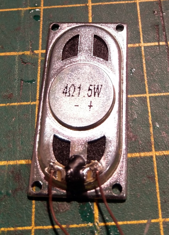
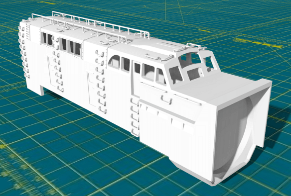
With just the ESU LokSound decoder and speaker installed in the C-855 chassis, as shown below, the loco ran reasonably well but it did hesitate a few times on some point work.

This hesitation was down to dirty contacts in the pickups.  As the power supply was briefly removed from the decoder the locomotive came to a stop and the sounds went off, then it went through its start up cycle again.  As the other two locos in the set are still trying to run, this can be fairly annoying.  As well as cleaning the contacts and wheels I decided to add some stay alive capacitance to each locomotive.  A stay alive system is just what it sounds like; it keeps the decoder alive when the power is briefly lost.  ESU do sell their own stay alive devices, which are very good, but they’re fairly expensive, so I prefer to make my own which also allows me to make them to fit whatever space I have.  The only components I use are capacitors, a resistor and a diode.

The capacitors are 220uF 16Vdc Tantalum capacitors, the resistor is a 100Ω 0.25w and the diode is a 1N4007.  These are all parts which are readily available from most electrical stores or online.

The capacitor is designed to be fitted to a circuit board and is very small, which is ideal for N Scale locomotives. 220uF means the unit has a capacitance of 220 micro farads. You can get similar size capacitors with more capacitance such as 330uF but the price goes up. The 16Vdc refers to the maximum amount of voltage the capacitor can handle; because N scale DCC systems run between 12v and 16v, and the decoder drops the voltage by around a 1.5v, the capacitor will be receiving between 10.5 and 14v, so I find these are fine.

Be careful when buying these Tantalum capacitors; there are a lot of cheap ones out there with a low quality control.  It may say 16Vdc but if they’re cheap that may be an approximation.  If you put too many volts onto a Tantalum capacitor it will blow up, very loudly and dramatically.  The best way I can describe it is like a Roman candle.  And you don’t want that happening inside your locomotive!  The SOO SD50 below just had that happen with some cheap capacitors and the flames went up in the air by about a foot and blew a hole in the shell before I had a chance to cut the power.  So I would recommend a quality supplier.

The Tantalum capacitors have two metal tabs on the rear to solder to and a strip on one side to indicate the positive connection.

For these locomotives I’ll be using a bank of three Tantalum capacitors connected in parallel, which will give 660uF.  That isn’t a lot and won’t keep the motor turning, but it will give a few seconds to the decoder to keep the sound running, which is all I need. With all three locomotives working together the momentum and power of two out of three will jog a stalled loco enough to get it moving again without the decoder losing power and restarting itself.  I’ve glued these three together with superglue.

I’m going to put the capacitors in front of the speaker.  There is room to put in more, and normally the more you have, the better, but I want the space for the other parts.

The resistor and diode perform two important tasks. They are both connected to the positive capacitor terminal and positive (blue wire) connection on the decoder.  The resistor is used when the system is charging.  Power flows from the positive connector on the decoder into the capacitor to charge it.  As it passes through the resistor the current is reduced, which causes the capacitor to charge slower than normal.  Otherwise the DCC command station would detect the inrush of current and think there’s a short circuit when you first put the loco on the track.   The diode is there to bypass the resistor when the stay alive system is in use.  If the track power is lost the power flows from the capacitor back into the positive connector, but we don’t want any resistance.  As the diode wire is thicker than the resistor’s I wrap the smaller wire around the larger, as shown below.

I then solder the connections.

And lastly trim off the excess.

The new ESU Loksound V5 Micro decoders have a Next 18 plug, as described in the earlier post, as well as six solder pads.

The two we’re interested in are shown below.  I have tinned the solder pads with solder.  The one on the right is the positive connection, which is the same as the blue wire.  The left pad is the DC negative or common ground for the decoder.

To join all the parts together I start with the capacitors.  Using the off-cuts from the resistor I join the capacitors together by soldering the wire to each pad.

I then solder the diode and resistor to the positive side ensuring the band on the diode is on the far side from the capacitors.  This is because DC power only flows one way through a diode, towards the band, and we want it to flow out of the capacitors to bypass the resistor when in use.

I then solder a wire to the diode and resistor and another to the negative side.

The assembly is then wrapped in Kapton tape, ensuring there is no connection between the negative and positive terminals, and fix it into the loco.

At the other end I solder the wires to the corresponding solder pads on the decoder, ensuring there is enough wire to allow the decoder to be plugged back into the socket.

The decoder can then be plugged back in and the chassis is ready to go.

All three chassis have now been fitted with stay alive units and the bodies have been fitted, but you’ll need to wait until next week to hear what they sound like when I’ll also show you how to program the decoders so that each of the six Alco 251C prime movers sound slightly different.

Plugging it all Together With Anderson Powerpoles

In July of 2016 I shared with you how we join our modular layout, ‘Solent Summit’, together electrically using ‘Chock Blocks’.  You can find the post here.  Since then we’ve improved on this system by using Anderson Powerpole plugs.

The ‘Chock Blocks’ worked well for several years but the more we used the layout, and the larger it gets, we started to notice more and more that wires would get pulled out, the pins in the male sections would need spreading to ensure a good contact, and we were chasing electrical problems.

So we looked around for another solution.  There are several out there and they vary in design and price, but in the end we settled on Anderson Powerpole.  These are not the cheapest but the quality and reliability, so far, has been outstanding.  These have also been the standard connector for the NTRAK Modular Railroading Society since 2005.

There were three things that stood out to us, other than the quality of the product.  Firstly, the plugs are universal, which means there is no Male or Female sections, just one plug which connects to any other Powerpole.  Secondly, the plugs can be assembled in any order to make a connector to suit your needs; if you connect a wire to the wrong location you can simply move the Powerpole.  Thirdly, the Powerpole casings are the same size for the three different wire size fittings so you can easily combine different wire sizes.

The only disadvantage to the system, apart from the cost, is you need a special crimp tool, but that’s it.

The basic system looks like this; a crimp tool, plastic connectors and wire crimps.

The connectors come in a variety of colours.

The crimp tool is fairly large but very easy to use, as you’ll see later on.

The crimp connectors come in three sizes; 15 amp, 30 amp & 45 amp.  As we’re working with model railways 15 amp is more than sufficient, but we also have some of the 30 amp crimps simply because they are designed for larger wire.  Below are the 15 and 30 amp crimps.  The circular part is for the wire and the shaped section fits into the plastic connector.

For my new Tehachapi Loop modules I’ll be using the 15 amp crimps.  This orange wire needs to be linked across the two modules.

I strip the wire back by about the same length as the circular section on the crimp using a regular set of wire strippers and twist the ends together.  Twisting the ends ensures there are no stray strands.

The crimp tool has three positions, one for each crimp size.  The tool is ratcheted so it won’t spring open, allowing you to place the crimp in the jaws without it falling out.  The wire can then be placed into the crimp and the tool squeezed.  Once the tool reaches the right amount of compression on the crimp the ratchet releases and the tool opens up.  As I said before, it’s very easy to use.

The end of the wire is now crimped and is very securely fixed.

The plastic housing has a metal plate inside which the shaped section of the crimp pushes over.  Once it’s in it won’t pull back out; the cutaway image below (from Wikipedia) shows how it fits.

The plug can then be added to a plug block which can be assembled in any configuration.  Each plug has grooves on two sides and a raised section which fit into the grooves on the the other two sides.  And as I said before should you get one in the wrong place, one of the greens for example, it’s easy to slide them apart and correct the positioning.

To make unpacking and packing the modules quicker, as well as protecting the wires in transport, we’ve glued a singe Powerpole plug to the underside of the modules so the connector group can be secured.

The Powerpoles push together easily and hold well, but when you want to pull them apart it can be done without a lot of force.

As you can see they’re ideal for modular layouts.  In the main connector I have several small wires and the larger main bus wires, which use the 30amp crimps.

The Anderson Powerpoles are available from lots of places including Amazon and Ebay as is the crimp tool.  We have now converted all of our modules to this system and so far it has proved to be well worth it.

Alco C-855 N Scale ESU LokSound Install – Part 1

As well as being an iconic-looking locomotive the huge Alco C-855 also had an individual sound being powered by two Alco 16cyl 251C prime movers.  Together they developed 5,500 horse power and would’ve really rumbled as they passed by.  ESU have captured the right sounds and made them available for their V4.0 and new V5 LokSound decoders so in this post I’ll show you how I install sound into these locomotives.

Although the chassis has a step down section at the rear of the locomotive I wanted to add a good size speaker to ensure the sound has some bass to it.  The easiest solution is to cut a section out of the top chassis as you can see below.

Cutting the chassis just behind the inner screws leaves enough room for the speaker and provides a plastic shelf for it to sit on above the worm gear. The worm gear is below the top of the plastic so it won’t catch the speaker.  The chassis has already had parts cut out of the chassis making it lighter.  But given the sheer size of the locomotive, the fact that it pulls like a tractor anyway, and it will be running in a set of three, a little more removed will not be a problem.

The new Lokssound V5 micro sound decoder is a neat package and comes with a good 4 ohm speaker already attached and parts to assemble a speaker enclosure.  This chip came with an 8 pin plug, but as it will be hardwired in, the plug will be cut off.

Unlike the V4.0 Micro decoders which had different plugs soldered to the decoder all the V5 decoders are actually the same.  Below you can see copper pads on top of the chip.  This is actually a removable part with a Next18 socket underneath.  Next18 means it has 18 wire connections.

The chip looks like this.  The six copper solder pads next to the plug are for auxillary functions 5, 6 & 7 as well as stay alive connections.

The underside of the socket has no connections.

The flexible cable can be cut off leaving the socket section and copper solder pads.  The pads include track power positive & negative, motor positive & negative, speaker positive & negative, front & rear headlights, auxillary 1 & 2 and the common positive.

I will be mounting the decoder at the front of the locomotive behind the cab.  There are two ideal power fixing points to connect to.  Bridge wires will also need to be run to the corresponding screws at the rear of the chassis because the glue used to extend the chassis isolates the parts.  See the previous post about fitting a decoder to read more about this, which can be found here.

The original chassis came with a light bulb for the headlight which was attached to the screws via a contact plate.  But as this will need four connections, and I’ve lost the original plates, it’s easy to make some more.  For this I tend to use the excess solid core wire from a resistor, as shown below.

I wrap the wire around the screw.

Solder the ends together.

Cut off the rest of the wire and it’s ready to go.

The one screw which is sunken into the chassis, behind the one with the new contact, can’t be modified in the same way.  For this one I simply strip off enough insulation from the wire and wrap it around the screw twice.  Then as the screw is tightened down it grips the wire.  Make sure you wrap the wire clockwise so as the screw is tightened it doesn’t undo the wire.

With all the connections soldered to the pads the socket can be seated into the area behind the front screw.  But as the chassis is metal it will short out on all the solder pads, so cover the area with Kapton tape first.

The socket can then be put in place and the wires taped down.  Remember to set the wires in the middle of the chassis otherwise the shell will not seat properly.

One thing to note is the decoder will be sat directly above the screws which are delivering track power so the decoder should also be wrapped in Kapton tape, except for the Next18 plug.

The ESU speaker enclosure comes in four parts.  A base, two thin sections and one thick allowing different heights to be made.  Even with the chassis cut down one of the thin sections will need to be left out.  I use superglue to fix the enclosure together and to the speaker frame, ensuring not to get any on the actual speaker.

The assembled speaker can then be placed at the rear of the chassis with the wire connections at the top facing forwards.

The top of the speaker is just about in line with the top of the decoder which sits just under the roof line of the shell.

You may have also noticed the brown wires from the decoder socket were not quite long enough.  I could’ve replaced them but it was just as easy to extend them, covering the joint with heat shrink. If you’ve never worked with heat shrink before I did a ‘how-to’ on it which can be found here.

With the decoder plugged in the chassis is now ready for its trucks and then testing.  This particular chassis is for a C-855 B unit so I haven’t added any headlights, but both the C-855 A units will have lights, so I added wires from the socket and included a resistor which is tucked under the front of the decoder.  Below you can see all three chassis ready to be fitted to their respective shells.

The chassis have been tested and sound very good but installing the shells will add an extra level of resonance, increasing the volume. Once they are totally finished and fitted I’ll share a video with you so you can hear all six Alco 251C prime movers running.

Choosing The Right Speaker For Your Sound Decoder

This week I have a ‘how to’ post to share with you about speakers and the importance of choosing the right one.

Sometimes I get locomotives in for repair which have been fitted with a DCC sound decoder and the sound simply doesn’t work.  There are several reasons for this and hopefully it’s something simple like a broken wire.  But sometimes the wrong speaker has been used and it’s damaged the decoder beyond repair.

Most manufactures supply speakers with their decoders, but as they often don’t know what you intend to fit it in, the speaker is a generic size, and in N scale this is never going to fit.  There are all sorts of sizes available as well as shapes as you can see below from this selection I had in my bits box.

Two of these speakers are supplied with ESU V4.0 decoders, the smaller speaker comes with the V4.0 Micro.  However, both are fairly large and it can be struggle to find room for them in many locomotives.  So they are often swapped for smaller speakers.  These then become available to be used with other decoders, after all they’re good speakers, but now there’s a potential problem which could damage the decoder, because they may not be compatible.

Speakers are measured in wattage, this is how much power they can handle, and impedance, which is the property of a speaker that restricts the flow of electrical current through it.  This is measured in Ohms.  If you put too many watts through a speaker, you normally just blow the speaker.  But if the impedance of the speaker is too low then more power is used in the amplifier than sent to the speaker and the amplifier over heats and blows.  The amplifiers on DCC sound decoders are ‘solid state’ which means they are made from electrical components only, no form of valves or vacuum tubes as you used to get in guitar and stereo amplifiers, but given how small the sound decoders are that is not surprising.  But this means there really is no tolerance for getting the impedance wrong.

Some speakers, such as the ones used by ESU with their V4.0 decoders have both values written on the back; 1.5w and 4Ohms.

If this speaker was used with a standard Digitrx, Zimo or Hornby TTS sound decoder it would blow the amplifier right away as these decoders are normally only rated at 8 Ohms.  The lower the Ohm value the more power runs through the amplifier.

All sound decoder manufactures should list, either in the decoder manual or on their website, what the max Ohm value is for their product.  But what if you have a speaker and you don’t know what the Ohm value is?  This can easily be measured with a multi meter which can read Ohms.  Below you can see I have the multi meter set to read up to 200 Ohms and when connected to the ESU speaker it is reading 4.3 Ohms.

So now you can select the right speaker to go with your sound decoder.  But going with the smallest isn’t always the best idea.  Normally the smaller the speaker the quieter it gets and it will have less bass.  One of the best ways to increase the volume and bass, without electric amplification, is to add a chamber to the speaker for the sound to reverberate in.  Putting a speaker inside a locomotive shell will do this naturally as the shell forms a box.  But the shell will not be airtight and as a speaker makes noise by pushing air the increase in sound will be small as the air escapes.  Adding a chamber directly to the speaker is the best way and the ESU speaker I measured earlier has just this.  The speaker clips into the box.  But due to the screw holes in the speaker plate and the wire holes it still isn’t airtight.

Digitrax supply their N Scale speakers with a pull-off strip which leaves a sticky surface around the speaker.  It can then be stuck to the chassis or inside of the shell.  But this doesn’t leave a lot of air for the speaker to push against.

I like to use cell phone speakers for my N scale locomotives as cell phones can be very loud!  Below is a Zimo sound decoder with a 8 Ohm speaker.  When soldering the wires onto your speaker remember that a speaker has a large magnet in it so as the soldering iron gets close make sure to hold the speaker down so it doesn’t jump up and attached itself to the iron.  They tend to get very hold and melt very quickly; don’t ask me how I know this!

In cell phones the speaker normally sits over a cavity and is stuck on to form an airtight box.  This is why some phones sound very loud and appear to have good bass.  I 3D print boxes to go with the speakers in different depths depending on how much room I have to work with.

This particular sound decoder is going into an old Rivarossi Challenger and that has lots of room in the tender so I’ll be using the larger box.

I use superglue to fix the speaker but it’s important not to get any on the actual speaker.  So, using the speaker bag, I put some superglue down and rub the box in it ensuring I get some glue on all sides.

Then I place the box onto the speaker and hold it till the glue sets.  Being superglue this doesn’t take long.

The speaker is now ready to fit into the tender and it will be considerably louder than any of the speakers in the first picture.

The thing to remember is to check the impedance.  Most new decoders now support 8 Ohm speakers, ESU going up to 4 Ohm. But a lot of older decoders, even ESU, may be 32 or even 100 Ohm only.

If anybody is interested in 3D printed speaker enclosures or cell phone speakers please get in touch via the contact page.

Alco C-855 R-T-R Build – All Together

Happy New Year!

2019 is here and what better way to start than to see a project completed.  My C-855 Ready-To-Run set of N Scale A-B-A Alco C-855 locomotives have been a challenging build but fun to do and I think the outcome is very good. This set are now on their way to their new owner.

The complete How-To series for the build of this A-B-A set can be found here.

Looking forward I have some more projects which need to be wrapped up and the next big one is the Union Pacific Rotary Snow Plow 900081.

I also have some updates for the DD35 as well as several replacement parts to share with you once we get stuck into the year.

So for now it’s back to the digital drawing board and on with 2019.


Alco C-855 R-T-R Build – Part 13 – Handrails

This week I’m covering the next part of my step-by-step build of a set of N Scale A-B-A ready-to-run Alco C-855 locomotives.  You can find part one of the build here.  This step is all about adding the etched brass handrails and ladders.

The handrails on these locomotive run between the sand boxes which are fixed to the outside of the bodies. To make painting the sides of the shells easier the sand boxes are separate parts.  Each locomotive has eight sand boxes; four on each side.  The A units have two cranked sand boxes which fit behind the cab.  The other six are rectangular.  The B unit has eight identical rectangular sand boxes.

The red stripe was created with a decal and will be finished with paint.

Because both the shell and the sand box have been painted it may be a very tight fit, so you’ll certainly want to do a test fit before you attempt to glue them on.  On the rear of the sand box is a lug which fits into the slot on the side of the shell: if the sand box doesn’t fit it could be because of the paint around the lug and gentle scraping with a craft knife will remove this.

To fit the sand boxes I use a toothpick or similar to add a drop of superglue to the slot then press the sand box into place.

The sand boxes on the other side of the A unit are a mirror image.  (And yes the shell above is a different locomotive, number 61, to the one below, number 60).

The brass etch fret has six handrail sections to install as well as four ladders.

The center handrails, and the longest, have four posts which fit into the top of the sand boxes.  Both handrails are the same.

The sand boxes have square holes 3D printed in the tops to accept the handrails which not only makes it easier to get them in the right place but also makes them a lot stronger, as with the sun visor installation described in my previous post about detail parts.

However as the sand boxes have been painted it’s possible the square holes are blocked with paint.  If that’s the case they can be opened up with a 0.4mm drill in a pin vice as shown below.  No 3D printed material needs to be removed and a few twists should cut through any paint blocking the hole.

The handrail can then be test fitted.

As both ends of the handrail are fixed by the sand boxes you may find that the handrail bows which it has done in the image below.  This could be due to several reasons such as the sand boxes being slightly too close together or the 3D printed shell may have shrunk slightly which can happen if removed from the printer too quickly.  But it’s hardly noticeable except in the handrail. In this situation I remove the handrail, dab some superglue onto the four posts and fix them into the sand boxes.  Once the glue has set I use a pair of tweezers to increase the crank next to the sandbox which will stretch out the handrail and remove the bow.

The crank in the image above is rotated clockwise and the crank in the image below is rotated anticlockwise by the same amount.

Each of the eight posts in the center of the handrail can now be glued to the shell.  I do this by dabbing a small amount of superglue under the post with the toothpick and holding in place until set.  I tend to use a small flat blade watchmaker’s screwdriver to hold them down.  The posts or handrails for the ladders are not stuck down yet to allow correct positioning of the ladders.

The next sections to be fitted are the handrails behind the cabs; the B unit doesn’t have these.  There are two in the fret and they are both the same.

As with the center handrail this part has two posts which fit into the top of the front sandbox.  There is also a square notch in the side of the cab, level with the sun visor, which the end of the handrail fits into.  With the exception of the ladder handrail section this part is glued in place, again with small amounts of superglue dabbed on with a toothpick.

The last two section are for the rear of the locomotive.  Although both parts are the same shape they are different.  Below is the left-hand side handrail as viewed from the outside.

From the inside you can see two reduced sections which are bending points.  The first is just before the first crank on the left and the second is just before the second post from the left.

This section of railing fits into the top of the last sand box and the other three posts have square notches in the 3D printed shell to fit into.

The very end of the handrail fits inside the lifting lug and lines up with the short section of handrail that was fitted in my last post.

The front of the B unit has the similar handrails to the rear, the difference being they are slightly longer.  So if you test fit them and the posts don’t line up vertically with the notches you have the wrong end.

Now all of the handrails are installed I fit the shell to the chassis, remembering to locate the headlight and secure with some Black Tack as described in part 11 of this build.

I fit the shell to the chassis now because the next parts to be added are the ladders and these are probably the most delicate part of the model and will be protected, to some degree, by the chassis.

The ladders are all the same but on the rear are two reduced sections.  These are not bending points but rather locating points for the handrails.  In the image below the ladder on the right is showing the rear side.

To fit the ladders I dip the top in a spot of superglue and place onto the side of the shell.  There are two locating lugs 3D printed on the shell and the ladder sits on either side of them.

The handrails are then glued to the reduced section behind the ladder, but they can also be glued to the shell if you like.

There are a few other parts on the fret which were added to it not knowing if they were needed.  These are some Multiple Unit or MU hoses which could possibly be used on the pilots and two tiny pipes, L shaped, which were designed to go from the cylinder on the fuel tank to the pipe 3D printed on the shell.  But as the existing pilots have MU hose molded onto the original Con-Cor parts I’ve decided not to use them.  As for the tiny pipes; these would prevent the shell from being removed if installed and from experience they get knocked off so easily I’ve also decided to leave them off.  However they are there to be used if you wish.

As for the assembly of the A-B-A set, that’s now it.  I still need to do a little paint touch up.  I also want to add some blackening on the vents and grills and also the number boards need to be sorted out.  Next week I’ll have some proper photos and hopefully some video of the finished set but for now here are a few shots taken whilst their still on the work bench.

As I said, in next week’s post I’ll have some shots of the finished set to share with you.