Bachmann N Scale 4-8-4 Replacement Gears – Part 2

In February of this year I shared with you my set of replacement 3D printed gears for the Bachmann N Scale 4-8-4, 3rd Generation.  You can find the post here.

At the end of the post I needed to make some modifications to the gears as the axels were still a little too loose on the wheels and the twin transfer gear was way too loose.  These changes were made and another set was 3D printed.

This time all the gears fitted well into the chassis, but I think I still have a problem with the twin gear as the motor struggles to drive all the gears.  Either the larger set are oversize, causing resistance between the gear and the worm, or the smaller set don’t have a deep enough trough between the teeth, which means the axel gears push the twin gear up into the worm.

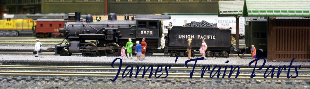
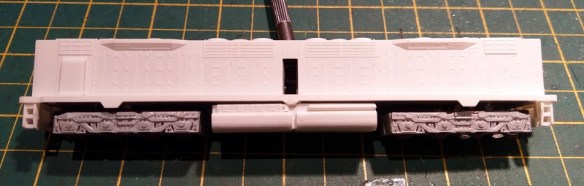
With the original twin gear fitted, and all the other 3D printed gears fitted, the assembly runs smoothly.   Below you can see the axels fitted onto the wheels with the chassis plate installed.

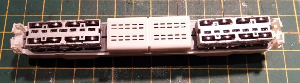
With the entire chassis assembled I started testing the gearing and discovered that there was a bind at the same point in every rotation.  After a little adjustment I was able to get it to run much smother.  However, on reflection the next time I do this when fitting the gears to the first set of wheels, as shown above, I’ll attempt to get the gears positioned at the exact same point on each wheel, as I think it was this that caused the issue.  If, as with diesel locomotives, there are no side rods, the position of the gears is not so critical as they will find their place.  Or if there are no internal gears, simply side rods as with the HO 4-8-4, then it’s just the quartering which needs to be correct.  But as this loco has both internal gears and side rods, the quartering needs to be correct as does the gear positions relative to each other.

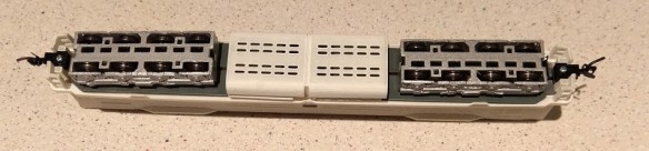
Below is a quick video of the chassis running with power supplied direct to the motor.

I’ll make the adjustments to the twin gears and do another test print, but in the meantime if you’re keen to get your N scale 4-8-4 back on the road and are happy to use all the other gears then a set is available here. In most cases, these 3rd generation 4-8-4 locos only need the axel gears to make a full repair as it’s the axels that split.

Once the new set arrives I’ll update you with the progress in a later post.

Bachmann HO US 4-8-4 Replacement Axle Shafts & Gear – Update

This week I have an update for the HO US 4-8-4 Replacement Axle Shafts & Gear set.

It appears I made a mistake with the hole diameter in the main drive gear, my apologies to anybody who has purchased one. The hole was larger than the hole in the axles meaning the rear wheels would not stay in the gear.

The good news is this has now been rectified and the current model on Shapeways is correct.  The parts are also available separately and they can all be found in my Shapeways Shop or via the links below.

Axles & Gears

Axles Only

Gear Only

However that doesn’t help anybody who has already purchased the gear set with an oversized hole. For those who did I will replace the drive gear for free. Please get in touch through the contacts page or email me directly at jamestrainparts@yahoo.co.uk and include the date which you purchased the kit.

Replacement gears seem to be in great demand at the moment and next week I should have some more to share with you for some UK OO locomotives.

EMD DD35 With Body Mount Couplers – Part 2

In last week’s post I shared with you my design and 3D print of an N Scale EMD DD35 with body mounted couplings.  You can find the post here.  In this week’s post I’m going show how well it worked.

The new EMD DD35 shell, as shown below, is sat on a modified Bachmann DDA40X chassis which has been shortened and had its pilots cut off.

The 3D printed pilots have pockets to receive a Micro-Trains body mount coupling.  This can either be a Type 1015 (Short shank) or a 1016 (Medium shank) and there’s a 3D printed hole in the pilot to receive the mounting screw.

I’ve used the 1016 as the extra length will help with the curves.  Because the coupling rotates slightly off of the screw, the longer arm will mean the coupling can swivel closer to the center of the tracks, which is the ideal location.  The further away the coupling gets from the center the greater the risk of it pulling the train off the tracks.

On our layout ‘Solent Summit’ the tightest radius is in the yards at 16″.  Below you can see the new DD35 coupled up to two originals with the truck mounted couplings.  The three run around the 180° bend with ease and there’s still slack in the couplings.

The middle DD35 has the standard McHenry couplings as supplied by Bachmann.

The McHenry sits a little high compared to the micro trains but the connection is good under tension.  Because the couplings naturally spring straight they will not couple up on the bend, they are way too far out of line, but they don’t seem to be affected once coupled.

In order to test the couplings properly I assembled a train powered by a GP35, GP20, GP7, the new DD35, a dummy DD35, a original powered DD35 and another GP20.  All followed by 42 cars and a caboose.

Apart from being lots of fun, the idea behind all the motive power, some 23,000 horsepower with the new DD35 in the middle, was to see how the couplings worked with pulling and pushing forces. The train, comprised of a lot of older rolling stock, had a lot of drag which added to the draw bar pull.  The big train made its way around the layout, through s bends and the 16″ radius yard curves, several times with no problems at all.

But as the other DD35s had truck mounted couplings, the GP locos being short and the box cars in the train also being short, all their couplings were close to the center of the track.  To make this a decent test the new DD35 needed to be connected to other long locomotives and freight cars with body mounted couplings.  And luckily there was one on the layout.  The train in the video below, built by my fellow modeller Chris, has two Kato SD80MAC locomotives pulling a long line of Atlas 85′ trash cars.

Both the SD80MACs and the trash cars have body mounted couplings so they will swing out further on the bends.

The trash car has Atlas Acumate couplings which as you can see work well with the Micro Train couplings.  There’s some swing on the Atlas coupling but it’s rotating about the end of the car, not the truck center point.

The Kato coupling seemed a little low, or the DD35 body may have lifted and I didn’t notice untill I got home and looked at the photos but it didn’t cause an issue.  The Kato coupling rotates about the end of the loco.

Leaving the East yard the train runs through an s bend, around at tight corner and out onto the layout and the DD35 with its body mounted couplings did this with ease.

It’s possible the shorter 1015 coupling will also work and if the tightest curve is 18″ or 20″ radius then it certainly will.  But I think 16″ is about the smallest radius for the new DD35.

I have a few other things to check and then I’ll make the new DD35 shell kit with pilots and body mounted couplings available to buy.

EMD DD35 With Body Mount Couplers – Part 1

This week I have a modified shell to share with you for my N Scale EMD DD35 project.  The new shell option incorporates body mounted couplers rather than truck mounted.

My DD35 3D printed shell is designed to fit onto a modified Bachmann DDA40X chassis which has truck mounted couplings.  Only the shell and fuel tanks are 3D printed, the trucks and pilots come with the chassis.  You can find the kit here.

The real DD35, and the DDA40X, has body mounted couplings, or rather chassis mounted, which allow the trucks to rotate freely under the chassis.  I originally decided to leave the truck mounted couplings on the model, simply because of the length of the locomotive.  As it’s so long, body mounted couplers will cause a problem with tight curves.  As the locomotive navigates the tight curve the coupling moves too far away from the center of the tracks and can pull the connected rolling stock off the rails or derail the locomotive. That’s also why Bachmann built the DDA40X model the way they did.

But some layouts have larger radius curves than others and I was asked if I could produce an extra part to allow body mounted couplers to be fitted.  So I did and they looked like this.

These came in the form of a pilot section with a cutout for a body mount coupling which, with a bit of modification, could be fixed to the underside of the shell.  You can read my post about them here and they can be found here.

But the ideal situation is to have the pilots 3D printed as part of the shell and that’s what I’ve done as you can see in the renderings below.

The new pilot section has the pocket and screw hole for Micro-Trains body mounted coupling.  The problem comes with fitting the new one piece 3D printed body section onto the chassis which is now too long.  As the pilot sections tuck under the chassis this makes it impossible to simply drop the body down onto it.

The original modified chassis, as shown below, has the pilots attached to the trucks and the chassis stops roughly where the pilots start.

To make the new shell fit, the first thing to do is remove the existing pilots.  These are held on with two screws which release the coupling and pilot.

The pilot mount is plastic and projects from the truck frame.

This needs to be cut off and that can be done with pair of side snips.

The chassis also had to be shortened by filing the ends.  From point to point the chassis needs to be 150mm (5.906″) long in order to fit inbetween the new pilots on the 3D printed shell.

With the chassis reassembled it now looks like this.  I also filed a chamfer on the four corners to ensure the shell was a good fit.

One other modification I made was to file off the four locating bumps on the sides of the chassis.  These normally located the DDA40X shell which has matching holes on the shell.  As the DD35 shell doesn’t have these holes and is held in place by the length of the chassis they are not required.  They will also cause the shell to spread if left in place.

The new shell, which is 3D printed in Shapeways Fine Detail Plastic, fitted onto the chassis and clipped into place, as did the fuel tank.

Once the shell has been painted I will fit the body mount couplers and get some videos of the DD35 traversing curves with its body mounted couplings. I’ll share that with you in another post.

N Scale Fixed Coupling Drawbar Update

This week I have another product update to share with you.  Unlike last week’s update, for the Minitrix eccentric rod crankpin, which was driven by improving the part, this time it’s simply about reducing the cost to you.

For many years I’ve offered N scale and N Gauge fixed link couplings or drawbars to use between rolling stock or, as I like to use them, between multiple diesels that stay coupled together.  This is really useful if you install a DCC decoder in one locomotive which drives both motors, you can read more about that here.  These drawbars are designed to fit into the Rapido style coupling pockets as you can see below.

To start with these couplings were offered in Shapeways FD (Frosted Detail) material but as that was removed from the available materials they automatically became available in FUD (Frosted Ultra Detail) and sadly the cost went up a bit.  When Shapeways restructured their material pricing again back in June of 2017 these became rather expensive.  However, just as with the Minitrix crank pins from last week I’ve combined the fixed links or drawbars into one piece making them much cheaper to order, as you can see below.

And I’ve also made the primary material BNVP (Black Natural Versatile Plastic) formally known as Black Strong & Flexible.  This is one of the cheaper materials; it’s already a good color for a coupling and can be used right out of the box.  Below you can see a set I’ve already ordered.

These are available in a variety of lengths and all come in packs of 6:

4mm
5mm
6mm
6.5mm
7mm
8mm
9mm
10mm
11mm
12mm
13mm

And if you’re not sure which lengths you need I do have two sample packs available:

Basic Sample Set – Containing 4mm, 5mm, 6mm, 6.5mm, 7mm, 8mm & 9mm.

Full Sample Set – Containing 4mm, 5mm, 6mm, 6.5mm, 7mm, 8mm, 9mm, 10mm, 11mm, 12mm & 13mm.

The length refers to the distance from the inside of the coupling pocket, for instance the 12mm is measured like this:

Next week I’ll have some real steam to share with you as I spent a day at ‘The Great Dorset Steam Fair 2018’.

N Scale Minitrx Eccentric Rod Crank Pin Replacement Update

This week I have an update to share with you regarding my N Scale Minitrix eccentric rod crank pin replacements.

Back in September of 2015 I wrote a post about repairing Minitrix steam engines which had suffered with broken eccentric crank pins.  You can find the post here.  These fit A3, A4, 7P (Britannia), 9F, US K4 and US 2-10-0 Decopod steam locomotives.

The crank pin, as illustrated below, has a square peg which fits into the actual wheel and a hole which receives a steel rivet linking it to the eccentric rod.

Although these worked and allowed the repair of the locomotive they did have a few issues.  Their small size made them rather delicate and it was easy to break one when attempting to refit the rivet.  So I originally offered spares in each pack as it was almost certain to happen on your first attempt.

This lead me to improve them by slightly increasing the size of the loop and the size of the rivet hole as shown below, the newer Mk2 pin is at the back.

This did help and made it much easier to reinstall the rivet.  But the issue of re-flaring the rivet was still a problem and I was finding it hard to do as I couldn’t get a supply of new rivets.  This lead me to start cutting part of the loop away to leave a ‘C’ shape which could be forced over the rivet.  As it is a ‘C’ shape it would not fall back off the rivet and the rivet didn’t need to be un-flared in the first place.  The original peg, what was left of it, could be cut away and the new one could simply be clipped in.

But it was hard to cut the hoop in just the right place without braking the hoop.  This lead me to upgrade the model again to include three Mk2 parts with a complete hoop and three Mk3 parts with a ‘C’.  Below you can see the Mk2 and Mk3 crank pins.  Supplying both, I thought, would give you the option as I was unsure as to how well the Mk3 ‘C’ type would work .

Then in June 2017 when Shapeways restructured their pricing system this model became rather expensive as each individual part had an additional $1 handling charge added to the cost.  But the answer is my new Mk4 version of the crank pin which you can see below.
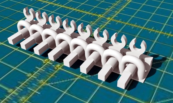
The crank pins are now supplied in a frame.  Although they are not attached to the frame they are 3D printed in the configuration shown above and the loops prevent the cranks from falling out.  The whole model is therefore treated as one piece.

There are eight cranks in each model, allowing for spares, and all have the ‘C’ shaped end which I’ve now used successfully on every loco I’ve repaired since printing the first ‘C’ shaped crank.  Also having spoken to several of my customers they confirmed they didn’t use the cranks with the full hoop at all.

And as the cranks are now held together it makes them easier to not lose!  When you need one simply cut the restraining hoop.

The new Mk4 crank pins can be found here.

Next week I’ll have an update on some of my 3D printed couplings.