Again this week’s post will be short as I haven’t had a great deal of time to work on any of the other current projects, but I did make some progress on the HO Baldwin DT-6-2000 body shell.
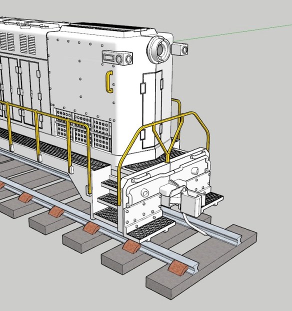
As this is a HO model, some of the details that were molded into the N scale body can now be made from brass, giving the larger model more detail. For example on the front of the loco, under the marker lights, is a grab iron which is now made from brass.
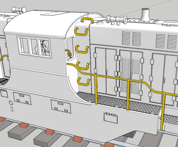
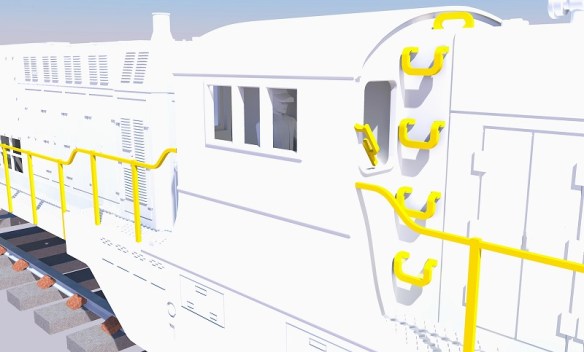
The grab irons which run up the side of the main body have also been widened. On the N scale model these were molded in, but when converted to brass, as shown below in a picture from a few weeks ago, I thought they looked too narrow.
I’ve now widened them and I think proportionally they look much better. Also on the image below, you can see I’ve reduced the size of the windscreen wiper as it was a bit too chunky before, making it look out of scale.
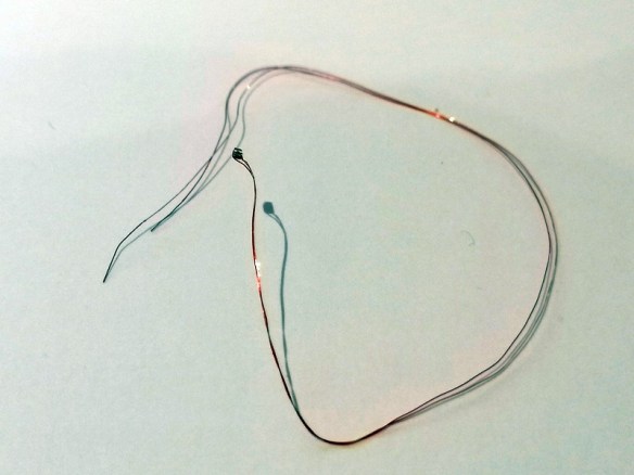
The last big addition for this week is the cab lights; for this I’m going to use a tiny surface mount LED. The LED itself only measures 0.9mm by 1.6mm and is 0.46mm thick. Luckily DCC Concepts sell these pre-wired as shown below.
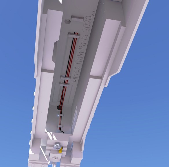
In the view below, which is a section through the cab, you can see the LED in the roof. I’ve designed a recess for the LED to fit into, and a route for the wires to pass through, keeping them clear of everything else.
The route for the cables positions them in the center of the shell directly over the DCC decoder and circuit board. The wires are also tiny so they and the LED can be glued into the recess to prevent them from moving.
Looking at the model for the HO scale, I keep finding little bits to re-design or change, but I think I’m now very close to ordering the first test print. Having studied a lot of the real locomotives in photos, I realized that different railroads had different features which were quite prominent. So as well as changing the shell to make it available as a Pennsylvania Railroad RT-624 I’ll also change it into a Trona Railway locomotive, for numbers 50 & 51, and maybe more if requested. Also for the Pensy, it’ll be available with the phone antenna, and in the later version, without.
Now it’s back to the drawing board to get it finished.
This week will be a short post as I haven’t had a great deal of time to work on any of the current projects, but I did make some progress on the HO Baldwin DT-6-2000 body shell.
The shell from the outside, as shown below, is complete, and this is mostly due to the fact it was already drawn for the N Scale version. The work I’ve been concentrating on is inside the shell.
Inside the shell, as well as the chassis, are lots of wires and these are often forgotten about when it comes to planning an install of a DCC decoder into a locomotive. This loco will have sound, lights, working couplings, and maybe a stay alive capacitor as well, which will create a lot more wires and take up space. Fortunately, being a HO scale loco there’s a good amount of space inside, but the wires can still be messy. It can be really frustrating to get everything fitted only to find the shell won’t push down that last 1mm because of the clump of wires in the way! So I’ve created loops for the wires to pass through which should hold them all in the right place and keep them tidy.
In the image below I’ve taken a section through the 3D model and you can see the wires running from the headlights and coupling motor up inside the shell and along the underside.
Each nose section has two loops for the coupling motor wires. These may prove tricky to feed through, but I think it’ll be worth it and will prevent the wires from being visible through the mesh grill. It’ll also keep them away from the truck towers.
The wires then pass through three, or four, if required, loops on the underside of the shell. I’ve allowed for more wire in case more things are added, such as number board lights or speaker wires. The black is the common wire with the reds powering a headlight and coupling motor each.
In the middle of the loco is the cab, and the cab interior will be the same part used for the N Scale version. My drivers, Bert and Ernie, will also be used again, one for each side. Normally you’d be able to see through the cab to the other side, but there’ll be a DCC decoder and circuit board in the way, as represented by the green block.
Having the crew and cab interior, I think, greatly improves the appearance of the loco. I may even put a cable path in to allow a surface-mounted LED to be fitted in the cab roof. Several HO scale locos I’ve come across have cab lights that automatically come on when the loco is not moving.
The shell is now very close to being finished, and I will get a 3D printed test model soon. There’s just a few more details I want to add and some checks to make, but then I think it’ll be ready. I still need to draw the brass etching tool so that it can be sent off to the etchers, and I may draw in a compartment for the speaker; I’m planning on fitting a new ESU V5 Loksound Decoder; these come with a small but powerful speaker and having a location for it to fit into will again make things tidy and easy to build. I’ll share the final 3D model with you when complete.
Atlas make lots of railroad locomotives and rolling stock in a variety of scales, and I have several of them because of their quality and they enable me to use the chassis for other builds. In particular, I use their C-628 and C-630 N Scale models as the donor chassis for my N Scale DT6-6-2000 and RT624 kits. The chassis has been revised over the years to make improvements, but one version has an issue with the driveshaft coupling to the motor failing. In this post I’ll share with you my fix.
Below are a pair of Monon C-628s; the rear one is actually a dummy using my 3D printed chassis kit.
The powered chassis is a standard design, used on many of Atlas’s N scale locos, with a central motor and flywheels.
The chassis is held together by the two screws near each end, and the fuel tank, which clips over both chassis halves.
Inside at each end is a driveshaft linking the flywheel and the worm gear, which drives the truck towers. These simply pull out.
The motor is clipped in a cradle which in turn is clipped into the chassis.
With the motor removed you can see inside the flywheel; there’s a plastic universal joint, and it’s cracked.
The universal joint is press-fitted over the axel and uses the friction to spin it with the flywheel. Even when cracked it’ll spin so the loco will probably run okay on its own. But as the load is increased, such as adding a train, the amount of force on the split universal is stronger than the friction, and the axel just spins. So if your loco seems to run okay, but won’t pull very much, this is most likely why.
The universal joint is a plastic tube with two pegs which fit into the driveshaft. The hole in the tube will be smaller than the axel to create the required tight fit but the constant pressure on this particular material causes it to crack.
Replacement universal joints are available from Atlas, but these have been known to fail as well. So I’ve 3D modeled the part and printed it in Shapeways Smooth Fine Detail plastic because it’s both accurate and also hard-wearing
The new part is a direct replacement for the original.
If the old universal is cracked it should simply pull off leaving a clear axel inside the flywheel.
I fitted the new universal by placing it with a pair of tweezers but not pushing it on fully, just enough to hold it in place. If it’s pushed at an angle it too may crack.
I then used a flat screwdriver, as to give even pressure, to push it on fully so the universal is all the way to the back of the flywheel.
And that’s it. The loco is ready to be reassembled.
These are now available in packs of two and four using the links below:
This universal is used in many of Atlas’ diesel locomotives and will fit all.
I’m juggling an HO project as well as testing recent 3D printed replacement parts, but my focus is on returning to work on customer’s layouts where possible, so who knows what I’ll be sharing next week!
Two weeks ago I shared with you the first 3D test print for my new HO scale DT6-6-2000, you can find the post here. As you may recall I had a few issues with the print, but this week the second test print arrived and the results are very good.
I reprinted the two truck center halves and the four gears as all had issues to be resolved. The final kit will need four truck center halves and eight gears.
The gears came out even crisper this time, I assume because the axel section of the gear is now a part of the gear rather than held in place by 3D print residue.
The gears up close are very accurate, but there’s still some residue on the axel which will need cleaning off. To do this I simply wipe it off with paper towel. The holes for all the gears will also need cleaning out and for this I use a drill to ream each hole. If it has 3D print residue in the hole it will cause the gear to bind and add drag to the motor. If all the holes bind it may even jamb up the gears.
This time everything fitted as planned. The clip covering the worm gear will need to be taken off, and the drive shaft removed, in order to fit it into the chassis.
The gears, as shown below, are simply positioned in place to check they are a good fit. Before I tested them under power from the motor I did all the cleaning mentioned above, and lubricated all the axel holes with light oil, from inside and out. Then, with the wheelsets removed, I checked that the sets of gears turned freely by running my finger along them. With the wheelsets refitted the whole assembly was a little tougher to turn, but this was expected given there are 3 more gears than in the original configuration. But once the driveshaft and worm gear was fitted I was able to turn the whole assembly by hand.
The test fit into the chassis was also good; below you can see the original truck on the left and the new one on the right now facing the right way for a DT6-6-2000 or RT-624.
The clip covering the worm gear holds the truck in place, and a pin in the underside of the chassis fits into a hole at the center of the truck, creating the pivot point.
The white of the truck center is barely visible through the truck side frames, but it can be painted, taking caution not to paint the axel holes. With the chassis reassembled, albeit with one new and one old truck, I lubricated the gears using oil designed for plastic gears from LaBelle. You can find a post about these products here.
The final thing to do was test the new truck, so I connected a basic DC controller to the chassis (there is no DCC chip fitted yet) to see how well it runs.
In the video below you can see I ran the chassis at full throttle in one direction then threw it into the other. Because of the two large flywheels, the direction change is not instant, but it’s still a heavy load on all the gears and they seem unaffected. The chassis is in a foam holder because the first time I did this the sudden reverse toppled the chassis over!
The new truck ran very smoothly and the slow speed looks okay, but the real test will be when it’s on some tracks. As I’m an N scale modeler I only have a short section of HO track at home, but later this week I’ll be able to test it on a layout. The chassis has an 8 pin DCC socket so I can plug in a chip and see how slow I can make it crawl, but I feel confident that I’ve resolved the issue with rotating the trucks, so now it’s just a matter of finishing the shell. I’m currently modeling the cab interior and I will share that with you when it’s finished and before we go to test print.
In January of 2019, I shared with you my design for a 3D printed axle set to fix Mainline steam locomotives with the large drive gear on the center axle. You can find the post here.
The manufacturer Mainline was incorporated into the Bachmann company and several of the designs stayed the same. These are what I call the large center gear models, and have the square shafts on the wheels, such as this modified Hall locomotive below.
But another popular brand which Bachmann also incorporated was Replica Railways. These locomotives, such as the LNER B1 below, have a similar design to the Mainline locomotives in that they are a split chassis design without wires, but the main difference is the motor and the power transmission to the wheels.
These have a totally different motor that drives the rear axle via a smaller gear than the Mainline locos. The side rods then drive the forward wheelsets which have ungeared axles.
Along with the rear gear being smaller, so are the axles, and sadly the wheels do not have square shafts. This causes the wheels to get out of quarter when the axles split and everything jams up. These are also made from the same material as the Mainline ones and it’s very common for them to crack and split.
This particular model had at some point been repaired in the past and the standard method for this was to glue the damaged axle in place. This means when the axle finally breaks down completely there is glue in the wheel which prevents a new axle being fitted. In the photo below you can see the pocket around the center stub is full of glue.
To get this out I drill several holes in the glue until it starts to break up and can be pulled out with tweezers. This also depends on the type of glue that was used.
Below you can see the holes I started drilling in the glue. Make sure you don’t go too deep and start drilling into the wheel. The way to check is to look at the swarf coming out. This particular glue was fairly transparent so as soon as a fleck of silver came out I knew I was as the bottom of the pocket.
Once all the glue is removed you should have something which looks like this. The rear axle, which has the geared axle, usually has traction tires. The center wheels have a larger connection for the side rods as this is also where the piston rod and eccentric rod attach.
The three axles have been drawn up and printed in my usual material, Shapeways Smooth Fine Detail Plastic. I’ve put them on a sprew, which doesn’t actually touch the parts, for ease of printing.
Because these axles have round holes it means unless the wheel is a good fit it can easily rotate inside the axle, but if it’s too tight the wheel will split the new axle, just like the original. Because the Mainline axles have square holes this is less of an issue. I’ve purposely drawn the hole in the axles ever so slightly smaller than the wheel center stub. I use a drill to carefully ream out the hole because, as I have shown in other posts, there will always be 3D print residue in the hole and it needs to be a perfect fit.
The axle can then be pressed onto the wheel; it needs to go all the way into the pocket.
The corresponding wheel can also be fitted but at this stage, it’s vital to get the quartering right. This means one wheel needs to be rotated 45° to the other. Each wheelset must be set in the same configuration.
All three wheelsets can then be replaced in the chassis.
Often at this point is I get asked which way round all the rods connect, so I’ll run through the sequence. Below you can see the simple side rod connects the center wheel to the front wheel. The joining side rod, shaped to represent a side rod joint, connects the rear wheel to the center.
The joining side rod is connected first, hooking over the connecting peg.
Second is the simple side rod sitting on top of the joining side rod.
Third is the spacer, with the grooved side facing up.
Fourth is the piston rod, which fits over the spacer.
And lastly, the eccentric rod fixes into the wheel with the special screw which holds it all together.
Testing the loco is always, hopefully, a happy moment and I like to test motion before the loco is put on the track. Below is a video of the first test. The slow speed is a little lumpy partly due to the motor but this went away once it had done a few laps of a test track.
Because the hole in the axles needs to be such a good fit and I’ve come across some variations in the size of the wheel pegs, I’ve provided a spare axle with the set so you can use this to check and see if it fits or whether it needs enlarging.
Despite being harder to install than the Mainline kit, mainly due to the quartering issue, these do work well as a repair and I’ve fixed many damaged Replica Railways locomotives which, without the part, would be redundant.
I have some more 3D printed gears in my latest test print and once I’ve installed and tested those I’ll share them with you as well.
Last Friday I had a delivery from Shapeways containing the new truck centers and gears for the HO Baldwin DT6-6-2000 project. They look good, and although there were a few issues, I thought I would share with you how they came out and what was wrong, rather than order some more and just show you the finished item.
I usually order several parts for different projects at the same time, with some of them combined on a sprew. Below you can see the truck center frames and lots of parts including the four new gears; they are located to the left of the sprew.
The four new gears are small and I didn’t want any parts of the sprew to touch them as it would need to be cut off, leaving a rough surface. So I surrounded them in a cage, which worked well.
The gears were free to move about, but couldn’t fall out.
Close up, the new gear is a good match for the original; the new gear is still covered in 3D print residue, which is why it looks a bit fuzzy.
The truck centers came out very well and appeared to be a direct replica of the original, with the desired changes.
The first problem came when I started fitting the gears into the holes. Each gear has a shoulder and an axel on each side. The axel fits into the hole and the shoulder acts as a spacer to position the gear in the center of the frame.
But in the 3D model, I’d forgotten to make the shoulder part of the gear, so it was 3D printed as a separate part which just happened to be close enough that the support material held it in place.
The axel and shoulder simply come off and you can see all the support material in the middle of the gear. The same thing happens on both sides so you end up with a flat gear with a hole in it.
Thankfully, this is why we print test pieces, and I was able to quickly fix the 3D model, so next time I print these gears they’ll be one whole piece. Sadly, for now, it means I can’t test all the new gears in the truck center. Interestingly though, once I had cleaned up all of the 3D print residue, the shoulder fitted into the hole in the gear so precisely I did wonder if I could make it work, but that made the axels too short and they wouldn’t stay in the right place. It does go to show how precise the 3D printer is.
The next test was the driveshaft and worm gear. These have brass bearings either side of the worm gear which clip or slot into the top of the truck center, and it fitted well allowing for good free movement, but without clamping the worm gear.
As you can see below I did try and fit it all together with the gears, and they did turn before they fell out. The big problem here is with the tubes which stick out from either side of the truck centers. The ones on the left are longer than the ones on the right. These tubes are the fixing locations for the truck side frames which hold the wheels and power pickups in place. One is longer than the other, because the shorter of the two also clamps the power pickups in place.
But as you can see below, I got these round the wrong way. The power pickup is clamped by the longer of the two tubes causing the truck side frames to flare out. And this made it impossible to properly test the trucks.
This error has also been fixed in the 3D model and a new set has now been ordered. To be fair, apart from the issue with the gears and the tubes, the truck centers came out very well, and with the corrections made, I feel we shall have a decent working truck with the asymmetric axels positioned the right way round. In the photo below you can see on the left truck, even though the side frames are flaring, the wheels are all in the right place.
These truck centers will work for both the Commonwealth and Tri-Mount Trucks, so they can be used for either the DT6-6-2000 or the RT-624 models. While the new truck centers and gears are being reprinted, I’ll finish off the 3D model of the shell, and I plan to share that with you next week.


You must be logged in to post a comment.