Drawing A Baldwin DT6-6-2000 Center Cab Part 3

So now the DT6-6-2000 is all drawn and the test print has been order it was time to think about the dummy version of the locomotive and how I was going to do it.  In this post I will share with you what I have decided to do.

Below is a rendering of the finished shell sat on the Atlas chassis along with the replacement truck side frames.

Finished Baldwin DT6-6-2000

The dummy version of this locomotive needs to look exactly the same as the powered version as I intend to run them together, recreating Mark McDowell’s image in the link below.

http://www.rrpicturearchives.net/showPicture.aspx?id=219383

The first part to do was the trucks.  Having already created the side frames with all their details and parts for the powered DT6-6-2000, I was able to use the same details for the outer face of the dummy trucks. The inside face of the frames are relatively smooth as they don’t require details, just axle pockets for the wheel sets.  I added the side frames to a similar arrangement I had already used with my UP Water Tenders.  Being a typical draughtsman I don’t draw anything twice if I can hep it.  The trucks for the tenders have evenly spaced wheels so I offset the bolster pin, I did this so the center wheel didn’t need to be removed to install in the pin.  For the DT6-6-2000 I wanted to do the same thing but as the wheels are already unevenly spaced in the trucks this meant the pin could be moved closed to the center of the truck as shown Below.

Baldwin DT6-6-2000 Dummy Truck

The truck has been designed to take 3 Fox Vally 36″ metal wheel sets (FVM3611), there are no couplings because they will be body mounted on the shell.

The truck for the other end is exactly the same, just rotated by 180 degrees.  As with my other trucks these are only printable in the Frosted Ultra Detail material from Shapeways.  This is because of the level of detail and the thin sections that are only achievable in this material, the bolster pins are also printed in the FUD to complete the set.

For the chassis I decided to make it out of the White Strong & Flexible material as I did with my DDA40X dummy chassis.  Because the DT6-6-2000 has those large side plates that hang down over the fuel tanks and air cylinders there is very little, if any, of the chassis that will be seen once the dummy locomotive is assembled.  WS&F is ideal because it is lot cheaper than FUD, it can be printed in black and it doesn’t need to be soaked in a solution to remove the waxy residue left on the FUD parts.

Although it is not really visible I still like to add what detail I can to parts so I included the fuel tanks and air cylinders to the underside of the chassis.  As you can see from the image below the fuel tank is hollow which allows extra weight to be added.  This will be important as the majority of the locomotive will be 3D printed and it will be very light.  With out the extra weight the locomotive will have a tendency to ride up over the rails and come off the tracks, especially if between the powered locomotive and a heavy train whilst going around a tight curve.

Baldwin DT6-6-2000 Dummy Chassis

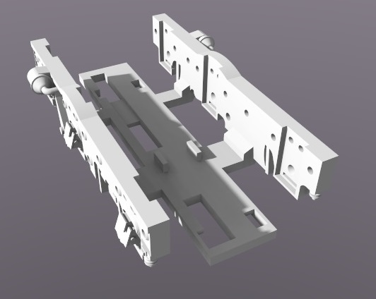
The chassis looks a lot chunkier than the dummy chassis I produced for my DD35 dummy.  This is because the design requirement for WS&F are thicker than FUD, and it also shorter.  I added the lip around the top of the chassis as a structural element, as with the tie across the top of the up stands.  The bumps on the up stands match the dimples in the shell, but rather than move them down for the dummy I left them in the same location, that way the same shell will fit on either the Atlas chassis or my dummy chassis.  Pictured below are the finished trucks and chassis, they will fit inside the shell using the same fixings and lugs as the Atlas chassis uses. Baldwin DT6-6-2000 Chassis & Trucks

And together the dummy and powered DT6-6-2000s should look something like this.

Baldwin DT6-6-2000 x2

The dummy is in the front, without the fuel and air tank detail on the dummy chassis there would be a big void under the locomotive from this angle.

The test print for the shell is due to arrive this week so in next post I should have an actual model of the DT6-6-2000 to share with you.

Drawing A Baldwin DT6-6-2000 Center Cab Part 2

Over the last few weeks I have been working on the 3D model for the Baldwin DT6-6-2000 center cab locomotive and it is now ready for a test print.  In this post I wanted to share with you some of the details I have included in this new model.

If you missed the first part of this model design you can find it here.  I finished the first part with the image below which showed an overall view of the shell at the then current stage.

Baldwin DT6-6-2000

Since then I have finished all the little details and fixed several of the issues that were not working.  The biggest issue was the size, or to be more precise, the length.  Although the 3D model has been accurately drawn, this shell has been designed to fit onto a powered chassis taken from an Atlas C-628 with the trucks rotated, as I illustrated in the first post.  The issue arose when the trucks were rotated they were not located in the same position as the DT6-6-2000’s trucks and they clashed with the bulkheads at either end.  To resolve this I have added 100mm at each end, which doesn’t sound a lot and in fact, in N scale, it works out to be an extra 1.25mm overall, but having tried to keep it as accurate as possible, suddenly adding 100mm made it look odd.  To hide this I dispersed the 100mm throughout the model by moving door sets up by 10mm etc and I don’t think you’ll be able to tell.  I also had to add about 60mm to the height because of the chassis being slightly taller but once again I don’t think it will be noticeable in N scale.

To make sure this would fit the power chassis snugly I also modeled it in along with all of its lumps, bumps and fixing points so these could be replicated in my 3D printed shell.  Below is an image showing the chassis fitted into the 3D model with half the shell removed.

Baldwin DT6-6-2000 Cut Away

I also modeled in the power chassis trucks without their side frames.  This is because I need to provide new side frames as the C-628 frames are not right for this model.  A fellow modeler has also produced side frames for this locomotive in cast resin and when this kit goes up for sale I will include a link to his website for anybody who would prefer to use those.

My truck side frames for this kit, pictured below, are designed to fit directly onto the power chassis trucks using the same fixing lugs.  The side frames also clamp the power pickup strips to the wheel tips so getting the size of the side frames right is very important; if they are loose the locomotive will have bad power pickup or even worse, will simply fall apart. If they are too tight the wheels may not turn easily and this will overstress the motor.

Baldwin DT6-6-2000 Truck 1

Another issue I ran into was that the C-628 trucks are not only taller but also have a lot more going on.  Consequently, when I put my frames over the power chassis trucks you can see way too much.  To resolve this I had to increase the height of the frames by 60mm and blank off some of the clear spaces. However, as pictured below, I don’t think they look too overworked, and on the plus side it adds strength to the print.

Baldwin DT6-6-2000 Truck 2

The other major detail I have added is the cab interior and engineer.  Just about all of the ready to run locomotives I have ever purchased don’t have engineers or crew in the cabs and given the capabilities of 3D printing it seems silly to leave them out.  The real DT6-6-2000 has a cab which stretches across the whole locomotive, and as there is an engine in each nose section, you can see through to the other side.  However with this model when you look into the cab from the side all you will be able to see is the C-628 metal chassis, so I have designed a cab section with a blanking wall that is a separate part.  As well as hiding the metal chassis this allows you to paint the inside of the cab and the engineer before fixing it into the shell.  I have provided a cab section with an engineer for both sides allowing either one of the engineers to be removed as required.

Baldwin DT6-6-2000 Engineer

The cab and controls look a little basic but remember this is for an N scale locomotive and they will only be visible through the windows, a bit like the image below.

Baldwin DT6-6-2000 Cab

And if the cab was illuminated with a nice yellow light from above this would look great!

The windows have a recess on the inside of the cab to make it easy to fit a small rectangle of clear plastic as glazing; I will provide a template in the instructions for cutting these to the right size. I have also included details such as the air horns, body lifting brackets and steps on the shell as shown below.

DT6-6-2000 Roof Detail

Behind the headlights I have included a cutaway so after drilling through the headlight an LED can easily be pushed in from behind.

The handrails are all separate parts and I have added holes in the shell which match up to lugs in the handrails, which makes them easier to install.  If you want to make your own handrails out of a thinner material, such as brass wire, the holes are designed to be in the right places so they can be used as guides.

And here is the finished 3D model

Finished Baldwin DT6-6-2000

The test print has now been ordered and in a later post I will show you how it came out.

Dummy Locomotive Chassis Kits

With the EMD DD35 kit being released earlier this year you may recall I designed a 3D printed chassis to be used with the spare EMD DDA40X shell.  Well the kit is now finished and complete with the correct trucks, as shown below, and available on Shapeways which led to a new section in the shop as well as on the blog site.

DDA40X Dummy Kit

The new section is ‘Dummy Locomotive Chassis Kits’ and can be found by clicking here or through the drop down menus at the top of the page.  Currently there are two kits available, one for an EMD DD35 which fits my 3D printed shells and one for an EMD DDA40X which fits a third generation Bachmann shell.

The kits are designed to fit directly under the shells, without the need for modifications, and include the chassis, trucks and bolster pins.  Wheels and couplings are the only extra things required and I also recommend some additional weight.  The wheel size and make depends on the model and that information will be available on the individual kit pages along with the coupling specification.

I recommend adding weight to the dummy locomotives as this will help them track better through turnouts/points and if you are using them between powered locomotives and a long or heavy train it will prevent them from pulling off the track on tight curves.  For the weights I often use old motorcycle wheel balancing weights; not only are these set weights but they are also very compact compared to car ones and fit nicely inside N scale shells.  Below is a selection of used weights from my local motorcycle mechanic, the bottom three are car ones so you can see how much better the motorcycle ones are.

Motorcycle Wheel Weigts 2

If you are lucky enough get new ones they have a sticky strip on the back that you just need to peel off.

Here you can see where I have used some of the weights to weigh down a Con Cor Alco PB dummy chassis which I fitted with a through wiring harness for DCC.  I did a similar thing with a set of Con Cor EMD E7s which you can read about here.

Motorcycle Wheel Weights

As I recommend metal wheels for the trucks it is also easy to add power pickups if required.  Some locomotives, like the DDA40X, have a flashing top light which will require power or, if the locomotive is going to be used at the rear of the train, red tail lights.

If, when using a power chassis for another project, your spare shell has details like a detachable fuel tank that are not required with your project, the new 3D printed chassis will have the same fixings so the details can then be attached in the same way.

The next dummy locomotive chassis kit will be for a Alco C-628 from Atlas. This is because I will be using the powered chassis form my new Baldwin DT6-6-2000 Center Cab and once again I will have a spare shell.  There will also be a dummy chassis for the DT6-6-200.

I also plan to do some dummy locomotive chassis kits for the odd shells I have laying around from other scratch build projects and they will be in a later posts.

Fordingbridge Model Railway Exibition – April 2014

This weekend Fordingbridge Rotary Club put on the first ever Fordingbridge Model Railway Exhibition and my club, the Gosport American Model Railroad Group, was invited.  So we brought our modular layout, Solent Summit, along with us and in this post I wanted to share with you some of the other layouts that were at the exhibition.

Fordingbridge is a Medieval town in the New Forest District of Hampshire, England and the local station, before it was closed on 4 May 1964, was part of the Southern Railway.  That being said the majority of the layouts were based on the Great Western Railway, a very popular modeling choice here in the UK.

As is often the case when we have our layout at a show, we get very little time to see  the other layouts properly, and I think I miss a lot of the true highlights and rolling stock they have to offer, but I have tried to get some shots that give you an overview.  Hopefully the layout owners will let me know if I have something wrong!Gorpeton Blymee  Fordingbridge - April 2014 1

The first layout I looked at was Gorpeton Blymee, this OO gauge layout belongs to members of the Wimborne Railway Society and they were also there to help operate it. The layout is a based on a fictional GWR station set between 1940 and 1950. Below is an overall shot of the layout, the main line emerges from behind the factory buildings on the left and runs through to the station area.  To the right of the picture are the yards for the factory.

Gorpeton Blymee  Fordingbridge - April 2014 11

The layout is setup so switching (or shunting in English) of the freight yards can be done without disrupting the main line movements, this meant that there was always something going on.  The controls for the yard were positioned at the front of the layout with the mainline being controlled from behind.

Gorpeton Blymee  Fordingbridge - April 2014 2 Gorpeton Blymee  Fordingbridge - April 2014 3 Gorpeton Blymee  Fordingbridge - April 2014 4 Gorpeton Blymee  Fordingbridge - April 2014 5 Gorpeton Blymee  Fordingbridge - April 2014 6 Gorpeton Blymee  Fordingbridge - April 2014 8

The layout was very nicely detailed with lots to look at, it had a nice feeling of being busy without being cluttered.  I found out that the factory buildings are actually US outline HO buildings but they worked perfectly in this situation.  I guess there is a shortage of large factory buildings for the UK market.

Gorpeton Blymee  Fordingbridge - April 2014 9 Gorpeton Blymee  Fordingbridge - April 2014 12

The next layout was Melcombe Abbas built by the Romsey and District Railway Modellers Society.

Melcombe Abbas  Fordingbridge - April 2014 1

This again is a OO layout and is based on a small terminus in Dorset.  The motive power and rolling stock is mostly Southern Railway but in British Rail livery used after nationalization of the railways.

Melcombe Abbas  Fordingbridge - April 2014 2 Melcombe Abbas  Fordingbridge - April 2014 3 Melcombe Abbas  Fordingbridge - April 2014 4 Melcombe Abbas  Fordingbridge - April 2014 5 Melcombe Abbas  Fordingbridge - April 2014 6 Melcombe Abbas  Fordingbridge - April 2014 8

Next to Melcombe Abbas was Aldermouth.

Aldermouth  Fordingbridge - April 2014 1

Aldermouth is an O scale layout built by James Edwards from the Farnham & District Model Railway Club.  It portraits a fictitious GWR station set in the 1930s.

Aldermouth  Fordingbridge - April 2014 2

Being O scale the level of detail is greatly increased and James has clearly spent a lot of time building up the scenes.

Aldermouth  Fordingbridge - April 2014 3

The front of the layout had an acrylic screen protecting the layout which made some shots a little hard to get.

Aldermouth  Fordingbridge - April 2014 4

Whilst I was watching the layout this little GWR 0-6-0 and shunter’s truck where working the yard.

Aldermouth  Fordingbridge - April 2014 5

In the station was one of my GWR favorites, their iconic diesel railcar.  Because of the shape and the colors of the GWR paint scheme they were affectionately named ‘The Flying Banana’ .

Aldermouth  Fordingbridge - April 2014 6

Several of the buildings also had interesting names, in the picture below the fish monger on the right is called C.P.L.Jones, anybody that has watched the BBC’s television program ‘Dad’s Army’ will understand.

Aldermouth  Fordingbridge - April 2014 7 Aldermouth  Fordingbridge - April 2014 8

The blue telephone box in the picture below is a police call box which was also made famous by the BBC with an unnamed Doctor.

Aldermouth  Fordingbridge - April 2014 9 Aldermouth  Fordingbridge - April 2014 10 Aldermouth  Fordingbridge - April 2014 11 Aldermouth  Fordingbridge - April 2014 12

Outside the entrance to the exhibition we also had a surprise visitor.

Bitza Steam Lorry  Fordingbridge - April 2014 2

Bitza is a freelance steam lorry that was fired up and running in the car park.

Bitza Steam Lorry  Fordingbridge - April 2014 1

The next layout was Bradbury Junction.

Bradbury Junction  Fordingbridge - April 2014 1

This is a OO layout of a GWR Country Junction.

Bradbury Junction  Fordingbridge - April 2014 6

The track work on this layout was really nice and it looked like it had been hand laid.

Bradbury Junction  Fordingbridge - April 2014 5 Bradbury Junction  Fordingbridge - April 2014 4 Bradbury Junction  Fordingbridge - April 2014 2

Kidwelly Castle was in charge of the passenger train sat in the station.

Bradbury Junction  Fordingbridge - April 2014 3

The layout had two loops running around the layout and around the back was a beautifully sceniced section of main line running through a cut on the hill side.

Bradbury Junction  Fordingbridge - April 2014 7

The color of the grass captured the full green we get here in the English summertime. Below is a video of Kidwelly Castle running through the cut with a GWR 2-6-2 small prairie tank going the other way.

In the same room as Bradbury Junction was the highlight for me.

Corris 1930 Fordingbridge - April 2014 1

Corris is a 009 layout built by Rod Allcock.  The layout represents the town of Corris in Wales on the Corris Railway in 1930.  This layout is simply beautiful and the level of detail is just stunning.  Talking with Rod he said he wanted to create more than just a layout, he wanted to create a picture that the trains run through, and I think he did just that.

Corris 1930 Fordingbridge - April 2014 2 Corris 1930 Fordingbridge - April 2014 3 Corris 1930 Fordingbridge - April 2014 4 Corris 1930 Fordingbridge - April 2014 5 Corris 1930 Fordingbridge - April 2014 6 Corris 1930 Fordingbridge - April 2014 7 Corris 1930 Fordingbridge - April 2014 8 Corris 1930 Fordingbridge - April 2014 9 Corris 1930 Fordingbridge - April 2014 10

The layout is very nicely finished in its own display stand, enclosing the picture.  The layout is lit by strips of LED lights.

Corris 1930 Fordingbridge - April 2014 11

Here is a video of a train running through the scene.

Looking from the left end of the layout you get a nice view through the station building and here is a video of the train coming towards you.

Rod either scratch builds or uses parts from kits to build his locomotives and they are very impressive.  They run smoothly and don’t have any issues with power pickup despite the limited number of wheels.

Corris 1930 Fordingbridge - April 2014 13

To give you an idea of the size, below are two photos with some of Rod’s locos in the palm of my hand.

Corris 1930 Fordingbridge - April 2014 15 Corris 1930 Fordingbridge - April 2014 16

What amazed me was the weight, the unpainted locomotive at the top of my hand weight more than many of my US outline diesels!  That helps explain why power pickup is not an issue with so few wheels.

The locomotive below was even smaller and is powered by a mobile phone vibration motor.

Corris 1930 Fordingbridge - April 2014 14 Corris 1930 Fordingbridge - April 2014 17 Corris 1930 Fordingbridge - April 2014 18

The final layout, not counting our own, was Holm.  This layout is a fictitious OO gauge  layout set between Wales and the West country in England and is based on the GWR.

Holm  Fordingbridge - April 2014 2 Holm  Fordingbridge - April 2014 3

The layout has some very nice detailing and felt to me exactly as it should, after all, I grew up between Wales and the West Country.

Holm  Fordingbridge - April 2014 10 Holm  Fordingbridge - April 2014 4 Holm  Fordingbridge - April 2014 5 Holm  Fordingbridge - April 2014 6

The layout even had that essential British building, the Pub!

Holm  Fordingbridge - April 2014 7

Holm  Fordingbridge - April 2014 8 Holm  Fordingbridge - April 2014 9

And to finish off the post I could not resist showing a few videos of our Layout, Solent Summit.  Here is a troop train headed by UP’s mighty Big Boy.

And finally, much to my surprise the troop train came out of the coal mine not through the main line, sack the signal man I say!

And that just about covers the Fordingbridge Model Railway exhibition for 2014.  A big thank you to the Fordingbridge Rotary club and to all the Exhibitors.


Drawing A Baldwin DT6-6-2000 Center Cab Part 1

A few months ago I was asked by a fellow modeller, through one of the model railroad forums, if I could draw and design a 3D printed shell for a Baldwin DT6-6-2000 Center Cab. So in this post I will show you what this locomotive is and how the design is coming along.

In 1946 the Baldwin Locomotive Works, who were already manufacturing small switching diesel locomotives, set about designing a locomotive with more power to be used as a transfer locomotive.  Its primary function would be to transfer rolling stock from one freight yard to another locally so it needed the power of a road locomotive but not the speed. It also needed to maintain the visibility and benefits of the smaller switching locomotives.  Baldwin’s answer was the DT6-6-2000 Center Cab.

Baldwin’s naming convention, DT6-6-2000, refers to several things: DT stands for “Diesel Transfer”, the first 6 refers to the number of axles, the second 6 refers to the number of axles powered by traction motors and the 2000 refers to the locomotives horsepower rating.

The locomotive, as the name suggests, has a centrally located cab allowing the engineer to see both ends which makes it easy to couple to rolling stock at either end. Road locomotives normally had a cab at one end with windows only facing forwards, they would either need to be turned at the end of the line or run in pairs with another road locomotive facing the other way.

Here is a link to a picture of Torna Railway No.51 out side the shops at Trona, California, November 7, 1970 courtesy of www.railpictures.net.

The DT-6-6-2000 is powered by two diesel engines, one for each three axle truck. The design was effectively two switching locomotives back to back sharing one cab.  The original prototype had a pair of 8 cylinder normally aspirated diesel engines (Type 608NA) but all the other production locomotives had a pair of 6 cylinder turbocharged diesel engines (Type 606SC).

Several railroads tried the locomotives and a total of 46 were made between 1946 and 1950, each with slight differences as the design improved. There is only one left now and it is preserved at the Illinois Railway Museum in Union, Illinois. The Elgin, Joliet and Eastern Railway purchased the most ordering 27 in total but for me I like the 6 ordered by the Atchison, Topeka and Santa Fe Railway mainly because of the fantastic black and white striped paint job, so for this model I am going to base it on AT&SF No.2601.

Here is a link to a great photo of 2601 at San Bernardino on the 18th April 1952

And another on the same day.

And again at San Bernardino on the 24th July, 1952

(The three links above are from http://www.snowcrest.net/photobob/ where you can buy prints of the photos)

As this is a locomotive that has never been mass produced in N scale before, not even in brass, there was no easy place to start.  The shell will be completely 3D printed so that is not a problem, but as to what power chassis to use we had to do some digging around.  The biggest problem with the power chassis is the trucks, unlike most other diesel locomotives the axles in the trucks are not evenly spaced.  The DT6-6-2000’s first axle is spaced further apart than the other two as you can see in the photo links above.  The answer came in the form of an Atlas model of an Alco C-628 as pictured below. ( The C-630 will also work as they have the same chassis).

Atlas C-628 1

The Atlas C-628 is a very good running model but the reason why this locomotive is perfect is because of the trucks as shown below.

Atlas C-628 2

On the C-628 they are the same as the DT-6-6-2000 in that they are not evenly spaced however they are facing the wrong way and the truck side frames are completely wrong for the DT-6-6-2000.  This is not an issue because the side frames are only cosmetic and pop off as shown below.

Atlas C-628 3

Also because of the way the trucks have been designed they can also be removed and re-installed backwards as shown below.

Atlas C-628 4

The chassis is now ready to be used for a DT-6-6-2000.  As the chassis is a bit shorter than the DT6-6-2000 I have designed the shell to fit onto it without any modifications, except for turning the trucks around.  The Atlas shell also has several areas designed to receive the lugs on the chassis so that it simply clips on and the DT6-6-2000 shell will be the same.  The couplings will be body mounted Micro-Trains.

The 3D model for the shell is almost finished and below is a screen shot showing the progress. Baldwin DT6-6-2000

The interior of the cab and trucks still require modelling and there are some small details to be added around the shell.  The hand rails look very chunky because they are modelled at the smallest diameter that can currently be 3D printed however they will be printed as a separate part so wire rails can be hand made if required.

Hopefully I will get the model finished over the next few weeks and get a test print ordered.  In a later post we will look at fitting the shell to the chassis and finishing up the model.


Running a Few Trains

The Gosport American Model Railroad Group had a running meet over the weekend for members to test new equipment and get part of the club layout ready for an exhibition in a few weeks time. So in this post I wanted to share with you some of the trains from the day.

I have mostly taken video this time and I am using YouTube to play them, for anybody who is not familiar with this you simply need to click on the video and it will start playing, also once it has started a symbol of a gear wheel will appear in the bottom right of the video, by clicking on this you can increase the quality of the video, which is recommended.

To start we have nice long Union Pacific coal train running past the power station.  The train is headed by two EMD DDA40X locomotives and an EMD DD35.  At the rear of the train there is another EMD DDA40X.

The first two DDA40Xs are Bachmann models, the DD35 is a 3D printed shell on a modified Bachmann DDA40X chassis, you can read more about this here.  The tail DDA40X is a dummy locomotive, it has been built from the spare DDA40X shell left over from the DD35 build and has been mounted on a 3D printed chassis and trucks.  You can read more about the DDA40X dummy chassis here.  As the dummy DDA40X has power pickups and the original lighting board, the flashing light on top still works, and the headlight has been replaced with a red LED as you can see at the end of the video below.

Keeping with the UP theme we also had an excursion train running on the layout headed by a UP 4-6-6-4 Challenger in two-tone gray, made by Rivarossi.

UP Excursion Train

This train has two extra water tenders, one pre-rebuild and one post.  These are both 3D printed and you can read more about them here.

The pre-rebuilt version, pictured above on the left, is slightly wider than the rebuilt version because a second sheet metal skin was removed in the rebuild.  In the pictures below you can just about see the difference in width.

UP Tenders 1 UP Tenders 2

The tool car behind the water tenders is a Con-Cor Amtrak express material handling boxcar that has been repainted.  The rest of the train is the Kato City of Los Angles set and I caught it rounding the corner past Ted’s farm.

Just before the excursion train left the station at Solent Summit a UP double header came through with  local freight.

Whilst at Solent Summit station the Canadian Pacific put in an appearance with a lumber train which had to wait for a passing mixed freight.

Over at the coal mine the Chicago & North Western trundles by with a local freight train.  Waiting in the team track is a Denver & Rio Grande Western 2-8-8-2 ready for a train.

The Burlington Railroad also runs through Solent Summit with a four car Zephyr as seen here and again over Hells Glen trestle.

Returning to the UP, and Ted’s farm, we have a set of EMD E7 with a streamlined passenger train.

The club layout is DCC powered and all the locomotives have a DCC decoder chip inside them, however these three locomotives share one decoder between them, you can find out more about this here.  They are also permanently coupled using fixed couplings which you can find here.

Whilst the E7s were in Solent Summit station the UP’s Portland Rose, it’s premier train on the Portland route, rolled into town.

The locomotive is another 4-6-6-4 Challenger in two-tone gray, this time an oil burner made by Athearn.  I think the photo below strikes a nice contrast between old and new as the steam powered heavy weight train was later replaced by the sleek yellow streamlined coaches and matching diesel power.

UP Portland Rose 1

And to finish up we have one more little coal train powered by the BNSF running past Ted’s farm.

The rest of the day was spent getting the layout ready for the public exhibition which I will share with you in a later post.