In last week’s post I started showing you how my new N Scale project is coming on, Alco’s C-855. And as promised in this week’s post I am going to show you how I intend to lengthen the donor chassis for this locomotive.
The chosen chassis, as modeled below, for the C-855 is going to be Con-Cor’s 4500 Gas Turbine/GE U50 chassis.
Although the chassis has the right trucks etc for the C-855 they are at the wrong centers and need to be spread apart by 10mm. That doesn’t sound a lot but in N scale it can make a huge difference visually, it’s 1.6 meters (5′ 3″) on the real locomotive.
I looked at several ways to do this and each time found a reason why it couldn’t be done that way. The main issue is the motor; it is centrally positioned in the chassis with two drive shafts powering the two furthest sets of trucks. The two inner ones are not powered. Spreading the trucks will also mean the drive shafts will no longer reach them. And if only one end is lengthened it may cause an unbalanced load to be applied to the motor. The motor hangs down in the frame and on the 4500 Gas Turbine/GE U50 this is concealed by a fuel tank mounted between the trucks. On a side note, the 4500 Gas Turbine didn’t have a fuel tank but a battery box in this location and I already offer a 3D printed replacement part to correct the 4500 Gas Turbine which you can find here.
The C-855 side frames hang down in this location which is a visual aspect quite unique to the C-855. You can see this on the shell render below. Again if the donor chassis was only extended at one end the areas where the motor hangs down would be visible on one side of the frame.
Therefore my only choice is to leave the motor in the center of the chassis and extend it in both directions. Because the chassis provides the strength and weight for the locomotive I need to do this in such a way that it doesn’t compromise the chassis. Also I want to make it easy to do.
I decided to totally remove the center section which holds the motor in place and replace it with a longer 3D printed part. Below you can see a rendering of the chassis showing were I plan to remove the section.
And then below is a rendering showing the main parts in the correct place.
The new section in the middle will actually need to be two parts, as pictured below. This is because the top of the chassis conducts electricity from one rail and the bottom from the other. Also adding more material into the 3D print adds unnecessary cost.
The two new parts have been drawn to match the sections which have been removed so they will clamp the motor in the right place, as you can see in the rendering below. The new parts will be printed in stainless steel which will maintain the weight required by this locomotive. I will also offer the extension pieces in plastic as a cheaper alternative. Where I plan to cut the chassis will form a natural step, making the joint to the new sections stronger.
The last part of the puzzle are the drive shafts which will now be equally 5mm too short. To resolve this I will be 3D printing an extension piece for both. Below is a rendering of one of the standard drive shafts. The circular cup gear on the end fits over the drive gear on the motor.
To extend this I have simply designed a part that will fit into this cup gear with the same configuration on the outside as shown below.
The new part will be glued into the drive shaft completing the extension.
With the whole thing assembled the lengthened chassis should look like this.
One more modification to the chassis will also need to be made at the cab end so that it fits into the C-855 shell. But until I finish the design work for the shell I won’t know the extent of the modification, so I will share that with you once I have 3D printed the new parts and have a real C-855 chassis to show you.
As I have said before I have a passion for the large locomotives of the Union Pacific Railroad and in this post I will share with you the first stages of my designs for Alco’s massive Century 855.
This locomotive, or rather set of three locomotives, were Alco’s answer to UP request for a 15000 horsepower set of locomotives to replace their Gas Turbines. The Gas Turbines were becoming increasing more expensive to run. 15000 horsepower could have been obtained by simply running six 2500 horsepower locomotives together such as GP35s. However UP were concerned that the running costs of six locomotives would be considerably higher than say three much larger locomotives producing the same overall power. So UP approached three of the main locomotive builders of the time; Alco, Electro-Motive Division (EMD) and General Electric (GE).
All three companies produced big locomotives for UP to trial that shared two main principles; they were all twin-engine units riding on a single chassis and they all had eight powered axles.
EMD’s offering as pictured below was the DD35, pre runner to the DD35A & DD40AX. The DD35 was effectively two GP35 bodies joined together riding on a pair of four axle trucks. It had no cab and was used as a booster unit. EMD’s demonstrator set consisted of two 2500 horsepower GP35 locomotives and two 5000 horsepower DD35 boosters. Together they gave the 15000 horsepower UP were looking for. This is a model I have already produced for N Scale and you can find it here.
GE’s offering was the U50, as shown below paired with a EMD DD35. This locomotive was built up from a pair of U25B locomotives on a singe chassis. The chassis and trucks for the U50 came from retired 4500 Gas Turbines that the UP had traded back to GE. So, as with the 4500 Gas Turbines, the U50 rode on four two axle trucks grouped in pairs and connected by span bolsters. Unlike the DD35 these had cabs and could be used as single 5000 horsepower locomotives or in a set of three to meet UP’s requirement. The U50 below is a production model made by Con-Cor.
Alco’s answer to UPs request was the C-855. The C stands for Century and this locomotive was part of their Century series of locomotive that covered everything from small switching locomotives to these massive road engines. The 855 refers to the numbered powered axles, eight in this case, and the horsepower. The pair of sixteen cylinder Alco 251C diesel engines put out 5500 horsepower and in 1964 this made the C-855 the most powerful locomotive for its time.
As with the U50 UP traded in retired 4500 Gas turbines but Alco only used the trucks for their new locomotive, the chassis was a totally new design. Alco built three locomotive as their demonstrator set consisting of a pair of A units with cabs and one cabless B unit. Together the set produced a formidable 16500 horsepower and had potential for being the dominant locomotive. But sadly due to poor performance UP did not order any more. The original set of three stayed in general service based out of North Platte, Nebraska for nine years before being scrapped in February 1972.
These locomotives are considered by many to be very ugly with their lumps and bumps and I am inclined to agree. However I think that they are so ugly they become interesting. These have never been mass-produced by a mainstream manufacturer in N Scale, probably because only three were ever made and they didn’t last that long.
The first thing I needed to sort out for this locomotive was the power chassis and for this I am going to use Con-Cor’s 4500 Gas Turbine/U50 power chassis as pictured below. This made sense as the trucks are the same.
The downside to using this chassis is it’s too short. As Alco only reused the 4500 Gas Turbine trucks and not the chassis they repositioned the trucks further apart. As this model is N Scale I did look at whether a bit of modeler’s license would be used, if the difference was small it may not be noticed. But as I started taking measurements it soon became clear that there was a fairly big difference and I wanted to get the locomotive right. To overcome this I will be 3D printing a metal extension piece to fit into the middle of the chassis. This will push the trucks further apart but keep the motor in the middle of the locomotive. I will cover that in a later post but you can read about how I drew the chassis ready for this in an earlier post which you can find here.
With the chassis decided upon and the modifications underway it was time to turn to the main body shell. Working from drawings and photos that I have been able to gather I have drawn the bulk of the main locomotive. Below are some work-in-progress shots of the 3D modeled shell.
There is still a lot of detail to add and finish off before it is ready to go for a test print but I am hopeful that this will happen by the end of February. As with my previous locomotive models the C-855 will have brass Additions which will include the handrails and roof walks as well as several other small details. The large sandboxs on the sides will also be separate parts to make painting an easier job. The shells for both the A and B unit will be available and both will fit onto an extended Con-Cor 4500 Gas Turbine/U50 chassis. I will also be making a dummy chassis available for each unit.
In next week’s post I will share with you the design for extending the chassis using 3D printed stainless steel.
This week, as promised in last week’s post, I will share with you some photos and videos from the Southampton Model Railway Society’s Exhibition which was held at Barton Peveril College on the 24th and 25th of January 2015.
This was a fairly big show and had twenty four layouts, twelve demonstration stands and lots of traders, all spread out over several big halls. The layouts were all British, except one, and covered all the major scales. As I was only at the show on Saturday I didn’t get a chance to see it all properly but I was very impressed with what I did see. This exhibition is also a very popular one and draws big crowds which meant that it was very hard to photograph several of the layouts. So if some layouts have more or better photos than others it is by no means a reflection on the layout.
Barton Hill
2mm/N Gauge layout built by Stan Potter from Swindon.
The layout is compact without losing the sense of a much larger railway; it reflects the EWS depot at Barton Hill as seen a few years ago.
The backdrop was also nicely painted giving sense of realism with a cloudy sky, typical for the UK.
Botleigh Old North Raod
4mm/00 Gauge layout built by Ian Corps of the Southampton Model Railway Society.
This is a fictitious engine shed on the Southern Region set in the 1960s.
Brighton East
4mm/EM Gauge layout built by David Smith from the South Hants Model Railway Club.
EM Gauge stands for Eighteen Millimeters. Although the scale is 4mm to a foot (1:76), the same as traditional OO, the spacing of the rails has been increased to 18.2 mm (0.717 in). This is an accurate representation rather than the OO track at 16.5 mm (0.65 in). The reason for this dates back to the early 1930s when manufactures had trouble fitting electric motors in small steam engines in the popular, now called HO, 3.5 mm to a foot (1:87). The manufactures increased the model scale to 4mm to a foot but left the track gauge at 16.5 mm (0.65 in) and OO was born.
The layout is set between 1998 and 2003 on a Southern Region rail terminus.
The hospital in the background is having some work done and the modeling of the scaffolding was a great detail.
Right at the front of the layout was a construction site scene which was also very nicely modeled.
Fairhaven
7mm/O Gauge layout built by Fareham & District Model Railway Club.
This layout is again set in the Southern Region and depicts a through station with a goods yard.
As well as very well modeled track work and scenery the attention to lighting nicely finishes the layout. The gentle glow coming from the signal box was very believable.
Hebble Vale Goods
4mm/EM Gauge layout built by Karl Crowther form Chitheroe.
This layout is also an EM layout so all the track had to be hand-built as well as all the rolling stock requiring wider wheel sets. I think the extra work was well worth it as this layout was superbly finished.
All the stone work was wonderfully done, I could not see any repetition in the stone pattern suggesting that commercially available wall panels hadn’t been used, neither could I see any joints. If there were any joints they were very well hidden.
Hollow Fosse
3mm / TT Gauge layout built by John Thomas from Cirencester.
This layout set in a fictions setting in the South-West Cotswolds represents a small rural branch line in the late 1950s and early 1960s. I particularly liked the track layout, it was very different for an exhibition layout.
Everything on the layout was scratchbuilt, although it was hard to see, all the tiles on the roofs of the buildings were hand laid, one at a time.
Leicester South GC
4mm / OO Gauge layout built by the Shipley Model Railway Society.
This was a big layout and was a big crowd pleaser with lots of trains running up and down the main line as will as in the big yard.
It is set between 1948 and 1963 and is modeled on an actual location a few hundred yards south of Leicester Central Station.
An interesting feature on the layout was the large goods warehous; not only was it a fantastic model but the tracks around it all worked.
Normally working tracks is not such a big thing but in this instance the builders had managed to model a working section where, in real life, box vans full of goods would have been moved by hand using pinch bars and the small turntables you can see in the photo below.
And to show you this working here is a video of a box van being moved from the back track to one of the front tracks.
As this was a big layout it needed a big yard, and as with all the trackwork in the front, all the trackwork in the yard was handlaid.
Here is a video of a passenger train leaving and a freight train entering the yard.
Another clever section of this layout was the engine shed link. As well as the main lines and yard there was another through track that in real life connects the engine facilities with the Lester Central Station where express engines were often changed, so on this layout locomotives running light would often trundle through.
Here is one more video of nice long trains running on this layout.
Littlebridge
7mm / O Gauge layout built by Norman Cronan from the Southampton Model Railway Society.
This fictional layout is set in the West Country and depicts a branch line in the 1950s to 1960s.
Lowe Quay
4mm / OO Gauge layout built by the Southampton Model Railway Society.
This layout represents a goods yard somewhere in the West of London in the 1950s and early 1960s.
The high line at the rear of the layout carried the local electric suburban trains that you can just see disappearing in the photo below.
Maindee East Shed
4mm / P4 Gauge layout built by Steffan Lewis from Barry, Glamorgan.
This layout was my favorite of the show, it was simply wonderful.
It is set in 1961 at Maindee East service area in Newport, South Wales.
The level of detail on the whole layout was amazing and it was finished off with a fantastic painted backdrop showing a really overcast cloudy day.
The layout also had its own lighting which helped create the gloomy effects.
Having worked on real steam engines I can confirm the level of dirt that comes with them and this layout has captured that perfectly.
And as it is set in 1961, when steam was approaching its zenith, the engines would have been worked hard and not cleaned as preserved locomotives are today.
This layout is P4 Gauge. It stands for Protofour and has a track gauge of 18.83 mm (0.741 in). Like EM Gauge, it is at a scale of 4mm to the foot (1:76). P4 is currently the most accurate fine scale for 4mm to the foot (1:76).
The layout also featured an integral smoke system which releases smoke all over the layout depending on where locomotive are at the time; sadly I was so mesmerised with the effect I forgot to take any pictures.
The painted backdrop also gave a great sence of depth to the scene.
Even the brambles and weeds encroaching on the edges of the site are fantasticly modeled.
The coal shoot at the back of the layout certainly looks like it has seen better days but the lights in the lower room really help bring it to life.
Masham
3mm Finescale/14.2mm Gauge layout built by Peter White from Salisbury.
This layout, similar to the EM layouts, is based on the TT Scale but with a correctly spaced track gauge of 14.2mm. With a scale like this everything has to be handmade.
The layout is set in Masham which lies in the lower reaches of Wensleydale in North Yorkshire. The scene is set in 1922.
Modbury Torr
3mm/TT Gauge layout built by Paul Hopkins.
This layout represents the proposed terminal of the Great Western Railway as it would have been at the end of the Yealmpton branch in South Devon.
Priors End
4mm/OO Gauge layout built by John Smerdon from Tadley.
This layout is a fictional terminal on the Southern Region set in the 1970s.
Tal-Coed
4mm/OO9 Gauge layout built by Chris Ford from Lewes.
The layout was built in a hurry to fill an exhibition space but was very nicely done. It is set in North Wales and influenced by the Tal-y-llyn and Ffestiniog railways.
Valencia
4mm/21mm Gauge layout built by Andy Cundick from Pewsey.
This layout was is set in County Kerry, Ireland. It depicts the end terminus of the line from Farranfore on the Mallow to Tralee. It was said to be the westernmost railhead in Europe. Although the scale is 4mm, the track gauge is 21mm because Ireland run on a broader gauge railway; theirs is 5′ 3″ instead of 4′ 8″1/2.
Wadebridge
4mm/N Gauge layout built by Salisbury & South Wilts Railway Society.
This layout is set in North Cornwall between 1955 and 1959.
Wherewithial Quay
4mm/009 Scale layout built by John Bruce from Ludgershall.
This layout had to be the smallest here. It measures 21″ by 18″. But it didn’t lack in anything for its size. The scene is set in Southern Cornwall and was built as a shunting (switching) puzzle. The operator has a set of cards which are shuffled, one is picked and the operator has to arrange the wagons in the correct order shown on the card. Then another card is picked and the wagons are re-sorted. It sounds easy but when space is limited it can be a bit tricky.
Yes Tor Junction
7mm Finescale/32mm Gauge layout built by Graham Hatton from Eastleigh.
This huge layout is O scale but again with the correctly spaced track gauge of 32mm. Once again this means all the track had to be handmade and the rolling stock had to have wider wheel sets fitted.
The actual station is fictious but the viaduct is modeled on a real one although at two-thirds the size, the viaduct is now a cycle way.
Here is a short video of a medical train rushing on with supplies after a quick stop at the station.
This lovely layout was very popular but I did manage to get a videos with something crossing that huge viaduct.
And lastly I want to give thanks to my friends at Model Railway Solutions (the baseboard people) for letting me use their stand throughout the day. Here is a short video of part of their display stand showing one of their helixes for N scale. This video has not been speeded up either, that poor little class 33 diesel was zooming up and down all weekend!
In next week’s post I will be getting back to the drawing board, well mouse and keyboard, and showing you the designs for my next big N Scale locomotive which will be coming out in a few months.
Back in December last year I shared with you my designs and 3D prints for a pair of O Scale Union Pacific Water Tenders for the excursion trains. You can find the post here.
In this week’s post, I wanted to show you how the finished tenders came out and tell you where you can get them.
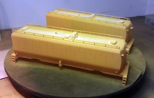
The computer models for these tenders, as shown below, are based on the HO version of this tender I had previously released. The main differences being that the handrails are part of the main body and details such as the ladders and steps have been thinned to make them look more realistic.
The trucks and chassis were also not 3D printed this time, unlike the N scale and HO Scale kits, but came from Lionel. They are spare parts for their Union Pacific Water Tenders: you can find the parts here. The reason for doing this is explained in the December post.
The kit, as shown below, has everything required from the chassis up to complete the tender.Once all the parts had been cleaned up, in the photo below, they were ready for spraying.
The first coat was done with Pollyscale’s (Floquil) UP Armor Yellow paint. These paints are perfect for spraying 3D printed models made for Shapeways’ Frosted Detail and Frosted Ultra materials as it’s an acrylic paint. Enamel paints do not dry properly when applied directly to the material and some other brands of acrylic paints don’t spray so well. Sadly this paint is no longer available. Straight out of the bottle it was a bit too yellow so for the second coat I added a spot of red into the paint which brought the right amount of orange tint to the color.
Once dry the yellow areas were masked off and the remainder of the tenders were sprayed with UP Harbour Mist Gray also made by Pollyscale.
Then, with the mask removed the tenders were ready for decals, well almost. I had a bit of gray bleed through onto the yellow which had to be brushed out. This was because a section of the mask had lifted. The trick with spraying is 95% of the time should be spent in preparation, the actual spraying part is really quick.
The trucks that come with the Lionel chassis are black so I stripped the parts down, then sprayed them with a basic silver. Again I used acrylic paint but as all these parts are metal I could have used an enamel paint.
I regularly like to do test fits as I go to check things are okay, and below you can see the assembled bodes and chassis with some of the detail parts laid out in front.
The yellow in the picture above still looks way too yellow for UP colors but this is a bit of an optical illusion due to the lights I have in my work room. Also once the red decals are applied it will greatly change the look of the color.
The next stage was to apply the decals. The lettering and flags where again supplied by Circusdecals, the red lining decals I made myself. The flag on the sides of Jim Adams is just about the same shape as the flag plate which is provided with the kit. This plate is very thin and I recommend gluing it to the tender before you apply the decal as decal setting solution will cause the plate to bend if unsupported. Wet slide decals also like flat surfaces to adhere to and these tenders are covered in rivets. Cutting out the decals as small as you can and then test placing them on the model is a good idea. If there is still a rivet detail under the decal I recommend carefully cutting that one-off with a sharp craft knife to create a flat surface.
I find taking pictures as I go also helps me check what I am doing. In the picture below you can see I had just finished setting the PACIFIC as the side of the tender is still wet. Looking at the photo I noticed I had the O in UNION rotated by 90°. As the O decal had not been down long I was able to lift it off and rotate it.
Once all the decals had dried I sprayed the tender with Testors Dullcote. This seals the decals to the tender. The last stage was to glue on the final details such as the tool boxes, ladders, cut levers and brake wheels. The cut levers and brake wheels were also spare parts ordered from Lionel. Below is an image taken halfway though this step. The tender in the background is a HO model.
Once complete the last thing to do was fit them to the chassis and take some photos.
And finally all three size tenders together; N, HO and O.
The O Scale tenders are available in two kits and in both FD and FUD materials from Shapeways.
The chassis and parts are available from Lionel here.
The decals are available on request from Circusdecals.
The price for Ready-To-Run models are available on request, please contact me through the contact page.
The new owner of the two O Scale tenders has promised some pictures and maybe some video of them running on his layout with big steam and I will share those with you in a later post. But for now there are more photos of this pair in the gallery.
In next week’s post I will bring you some photos and videos from my visit to the Southampton Model Railway exhibition which was held at Barton Peverill college in Eastleigh.
Towards the end of last year I shared with you my designs for a Baldwin RT-624 for the Pennsylvania Railroad, you can find the post here. In the post I said that the RT-624 would be the first of my kits to be available in the XHD material. In this post I want to show you how some of the XHD parts came out.
XHD stands for Extreme High Definition and is a term 3D Systems use for their 16 micron layer thickness setting on their Projet 3D printers. The majority of my 3D printed parts are printed by Shapeways in their Frosted Ultra Detail material. FUD is also printed on a Projet machine at a 29 micron layer thickness, 3D Systems call this UHD or Ultra High Definition. With 3D printing layer thickness, the lower the number the better the quality of the print. But that does come at a price, with a smaller layer thickness the 3D model will take longer to print.
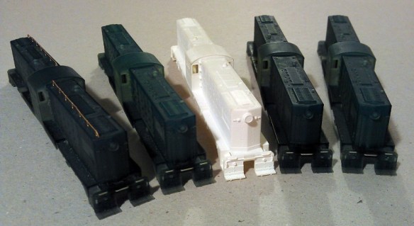
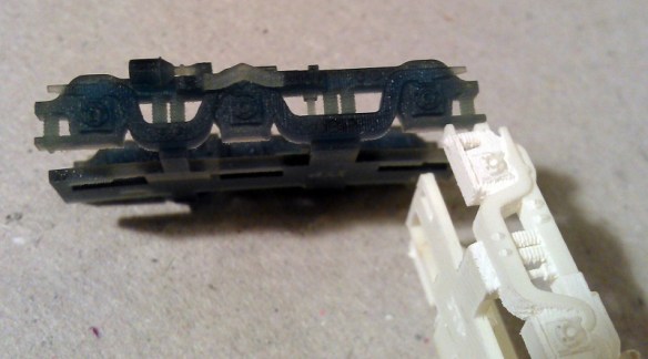
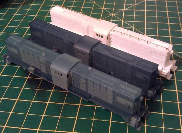
My first order of XHD prints was for four RT-624 kits as shown below. The shell in the middle is a Shapeways print in their FUD material and the shell on the left has a set of brass Additions train phone antenna test fitted in the roof. The four XHD shells are shown here as delivered from the printers.
The first thing you notice is that the XHD prints are blue, whereas up untill now all my prints have been white. They are not blue because they were printed at a 16 micron layer thickness but because they were printed in a different material. Shapeways use 3D Systems’ VisiJet® M3 Crystal material for the FUD prints but my 3D printer in London uses 3D Systems’ VisiJet® M3 Procast material. The main difference, apart from being blue, is that the Procast is designed for lost wax jewelry casting and is perfect for very small details. It is still as permanent as the Crystal but it has a slightly lower tensile strength and higher tensile modulus, which means that it is just that little bit more flexible and therefore less brittle.
The main question is how much better is the 16 micron layer thickness compared to the 29 micron? I must point out that the FUD shell used for this comparison has not been cleaned as thoroughly as normal; it still needs some of the powdery residue cleaning off. Below are the kits in both layer thickness. Initially they look pretty much the same. The Shapeways FUD model has all the detail, everything fits perfectly and it has been used to make some fantastic models, please see the RT-624 Gallery here.
It’s only when you get very close that you can start to see any differences. Looking at the two images below the roof of the locomotive is curved and in the FUD the curve is not quite as smooth as in the XHD.
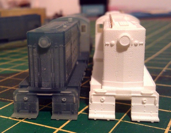
Orientation also plays a big part in how well a 3D print comes out. The top of the print will always be the best finish and any area that comes into contact with the support material also runs the risk of a slightly rougher finish. These XHD prints were printed as if they were sat on the locomotive chassis. This is the most expensive way of doing it because, just as if you were printing an upside down bath tub, the whole of the locomotive shell had to be filled with support material to print the top. The benefit of this is that all the detail on the top comes out very clearly. In the photo below you can see the lifting brackets and bolts around the exhaust stack are crisply printed. The details are still printed on the FUD model and are just as visible but they are just a little bit fuzzy. Don’t forget these details are tiny, the lifting ring is only about 1mm (0.039″) wide.
With smaller parts such as the fuel tanks, as you can see in the image below, it is very hard to see the difference between the FUD and the XHD prints.
With the trucks the two differences I could see were firstly that the XHD had a better definition on the tiny springs cast into the frame, and secondly the FUD has a better overall look. Both printers have heads that move over the print and the higher the definition, the more any offset calibration will show up in the print as vertical lines. So although the XHD print has better detail, the lower definition FUD print doesn’t show these vertical lines. Both prints show the horizontal lines made by layering the material as they print and the XHD layers are much smaller, but it has the added vertical lines from the moving print head.
Again with details like the cab interiors and horns it is very hard to tell the difference between XHD and FUD as you can see below.
Another advantage with specifying the XHD orientation is the quality around the sides is uniform, that is to say it is the same on all four sides. Sometimes with the FUD prints one side can be rougher than all the others if it was on the bottom next to the print tray.
As with the FUD prints the XHD has to be cleaned to remove the waxy material left over from the print process. Below is a shot showing a FUD print, an XHD print in the middle and a cleaned XHD print on the left.
The cleaning process has taken some of the blue colour out of the print, here are some more shots of the model after it has been cleaned.
As you can see in the photo above the XHD can still suffer from roughness under overhanging details, and as with the FUD this area will need a little scrub. I find a toothbrush does this nicely.
So all in all is the XHD print better than the FUD? Well, I think it comes down to personal preference as well as your budget. Currently the XHD prints are about three to three and a half times the price of the FUD prints. The really fine detail is sharper on the XHD but once painted the difference may not be so clear. The XHD has the advantage of having a uniform finish on the sides but it can still suffer from rough areas which come into contact with support material and under overhangs. The calibration of the particular print machine can affect the quality of the 16 micron print head, causing vertical lines. It may also depend what you want to use the 3D printed shell for; on smaller, more personal layouts where you are closer to your trains it is important to have as much crisp detail as possible, whereas on larger layouts when you are at least a few feet away from the trains such small detail may not really be visible.
I think the detail on the XHD prints is superb, and I’m really excited that 3D printing is able to offer such high definition, particularly for us N-scale modelers. However, in my particular layout the cost of these prints is a little high compared to the FUD which is still a very good print. I anticipate that this level of XHD printing will become more viable to mid-budget modelers like myself in the future. If you have the budget, I would recommend these XHD prints.
If you would like any of my products printed in XHD please contact me through the contacts page and I can give a quote.
In next week’s post I will be sharing with you the finished O scale UP excursion train tenders and letting you know how to get them.
This weekend I was at the Gosport American Model Railroad Group’s running meet and we set up several layouts including most of our N scale modular layout, Solent Summit. This gave me the perfect opportunity to test out my new 3D printed chassis and trucks for my spare Atlas C-628 shells.
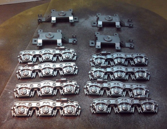
The new chassis, as pictured below, has been designed to fit under either a C-628 or C-630 shell made by Atlas. I now have a few of these spare as the powered chassis have been used for my 3D printed Baldwin DT6-6-2000 and RT-624 (DT6-6-2400) shells.
I also designed the chassis so it could be used as a simple dummy without any working light or electrics. Alternatively it could be used with custom power pickups to supply the original lighting board or maybe a sound decoder. The power pickups, as shown below, are axle wipers and are made from 1mm wide phosphor bronze strips. They fit into the groves and guides printed into the underside of the trucks.
In addition to the axle wipers a circuit board mount has been 3D printed to hold the original circuit board in the correct place. This are the white parts you can see in the first two photos above and they fix into the chassis using sprung hooks. There are holes in the chassis at the hook locations so the parts can be removed by pushing the hooks from the other side with a small screwdriver.
The chassis shown above is the third version I have developed. For the first I used parts that I had already drawn for another dummy chassis but this put the bolster pin, which is the swivel point of the truck, in the wrong location. This meant as the chassis tried to negotiate corners the trucks swung out too far and fouled on parts of the shell which hang down beside the trucks.
The second version was reconfigured to put the bolster pin in the correct place but although the trucks now rotate correctly the brake pistons, protruding from the cylinders on the side of the trucks, were ever-so-slightly too long. These also fouled on the hanging parts of the shell on tight corners.
With the third version all the issues have been fixed and below is a trio of Alco C-628 locomotives. Two of them are dummys; can you tell which ones?
The Southern Pacific Loco, No 7102 on the left is a dummy, but what about the other two?
The Monon locomotive on the right is the dummy. The only visible difference is the colour of the trucks; I painted the dummy trucks with a silver instead of a gray, but with a light weathering on both of them they will become almost identical.
The SP Loco No 7102 is fitted with the circuit board mount and the original circuit board. Our N Scale layout, Solent Summit, is a DCC (Digital Command Control) layout and as such the track is powered with 16v AC. This means that both front and rear lights on the dummy locomotive will be on at the same time as shown below. On a DC (Direct Current) layout the lights will only come on in the direction of travel as normal. The Monon locomotive behind SP 7102 is fitted with a DCC decoder and is currently set to the forward direction with the lights on.
For most of the day I only ran the pair of Monon C-628 locomotives with the powered locomotive in front and the dummy behind. Below is a short video of the pair running through Priddys Yard, past Ted’s Farm and into Solent Summit station. As you can see the dummy unit has no issues with the curves or drag though the couplings from the train. The slight hesitation is due to a short elsewhere on the layout, the dummy loco was not phased by the jolt.
In Solent Summit the pair did some switching, and here you can see the dummy being propelled through the crossovers without any issues.
Here is another short video of the train leaving Solent Summit.
This dummy locomotive is ideal for mid train helpers, rear pusher service or for simply adding to your locomotive roster by saving your spare C-628 or C-630 shells.
The dummy chassis kit for the Atlas C-628/C-630 is available here.
A small bit of trivia: The Monon Railroad ran through the state of Indiana before it was incorporated in CSX Railroad. The Monon line actually passed through a town called Gosport at Gosport Junction so running them at the Gosport American Model Railroad Group’s running meet seemed very appropriate, even if it was in the UK.
In a future post I will share with you some videos of dummy units working as mid train helpers & rear pusher on much longer trains.


 And then below is a rendering showing the main parts in the correct place.


 There is still a lot of detail to add and finish off before it is ready to go for a test print but I am hopeful that this will happen by the end of February. As with my previous locomotive models the C-855 will have brass Additions which will include the handrails and roof walks as well as several other small details. The large sandboxs on the sides will also be separate parts to make painting an easier job. The shells for both the A and B unit will be available and both will fit onto an extended Con-Cor 4500 Gas Turbine/U50 chassis. I will also be making a dummy chassis available for each unit.


 This layout is also an EM layout so all the track had to be hand-built as well as all the rolling stock requiring wider wheel sets. I think the extra work was well worth it as this layout was superbly finished.


 Everything on the layout was scratchbuilt, although it was hard to see, all the tiles on the roofs of the buildings were hand laid, one at a time.

 This was a big layout and was a big crowd pleaser with lots of trains running up and down the main line as will as in the big yard.


 And to show you this working here is a video of a box van being moved from the back track to one of the front tracks.


 Masham


 And lastly I want to give thanks to my friends at

 Once all the parts had been cleaned up, in the photo below, they were ready for spraying.


You must be logged in to post a comment.