Fitting Micro-Trains Body Mount Couplers To Older N Scale Freight Cars

With the NMRA (BR) Convention coming up this weekend I decided that some of my running stock needed some attention before the show.  A lot of my older rolling stock still has the Rapido style couplers and some of the newer stuff has Atlas’ Accumate couplers.  My preference for couplers has always been to use Micro-Trains as I have found them to be the most reliable.  In this post I will share with you how I convert older rolling stock to MT couplers in a fairly cheap way.

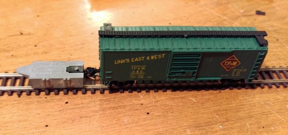
The box car below is a typical 40 foot car with Rapido couplers fixed to the trucks.  By far the simplest way to convert this car would be to buy a set of MT trucks, which come with couplers pre-mounted, to replace the originals.  However this can become very expensive if you have lots of cars to convert.

Micro-Trains Body Mount Coupler Fitting 1

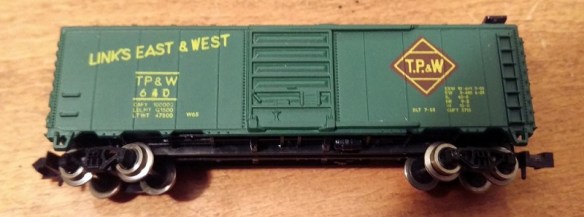
Another slightly cheaper alternative is to buy an MT conversion kit that will replace the coupler in the truck.  These can be a bit tricky to fit but work very well and you get to keep the original wheels.  The car I’m converting has metal wheels which are clean and in good order, making it a good runner.

For me the cheapest option is to use body mounted couplers.  Again this means you get to keep the existing wheels and trucks but the existing couplers are removed totally.  The new couplings are fixed to the underside of the car chassis.  This is actually more prototypical and transfers the weight of the train through the chassis, bypassing the trucks and bolster pins.

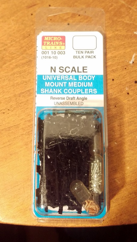
The MT body mount couplers are available in pairs or in bulk packs as shown below which is certainly the cheapest way to buy them.

Micro-Trains Body Mount Coupler Fitting 2

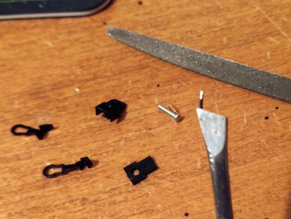
To make the change you will need a few basic modeling tools as shown below.  I use a small watchmaker’s screwdriver, flat file, craft knife, needle nose tweezers, flat end tweezers, MT gauge, pin vice with a drill (from the MT Tap & Drill Set – 00-90), side cutters & pliers.

Micro-Trains Body Mount Coupler Fitting 3

To start you should check that the car is in good running order.  You can see I have already changed the left hand coupler.

Micro-Trains Body Mount Coupler Fitting 4

The body should simply pull off the chassis and can be put to one side.

Micro-Trains Body Mount Coupler Fitting 5

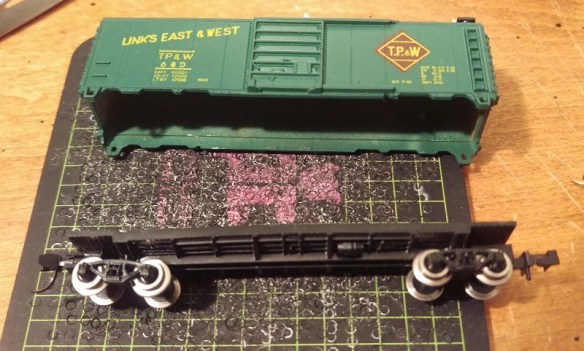
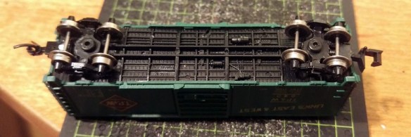
While the body is off it’s a good chance to check that the weight inside the car is properly secured; it’s normal for this to be rusty as it’s simply a strip of unprotected steel.  If the weight is loose simply glue it back into place before continuing.

Micro-Trains Body Mount Coupler Fitting 6

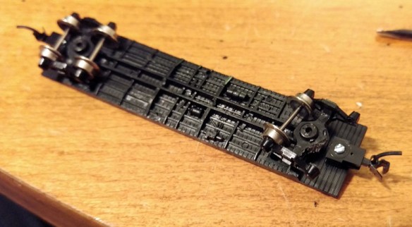
Next remove the truck by pulling out the bolster pin.  You can do this either with the pliers or by simply pulling on the truck.  Make sure the bolster pin does not fly off.

Micro-Trains Body Mount Coupler Fitting 7

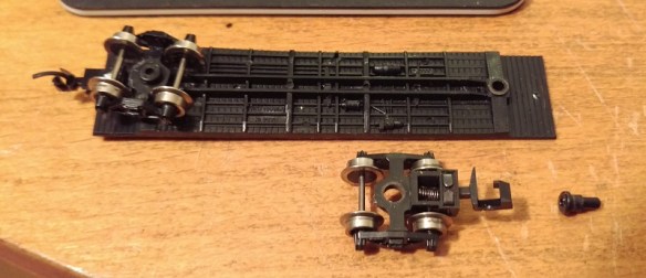
With the truck removed the front wheel set can be taken out by gently pulling the truck side frames apart.

Micro-Trains Body Mount Coupler Fitting 8

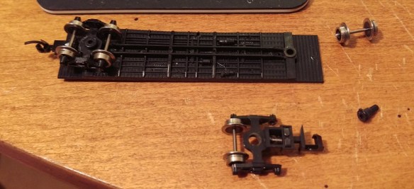
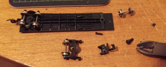
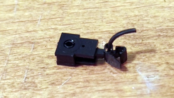
Then using the side cutters snip off the coupler leaving enough material surrounding the bolster pin hole.  You won’t be able to do this in one snip as the truck side frames will be in the way.  I find five snips normally does the trick.  Once finished the top of the truck needs to be flush otherwise it may hit the new coupler.  If the area where you sniped is a bit rough you can use the file to smooth it out.

Micro-Trains Body Mount Coupler Fitting 9

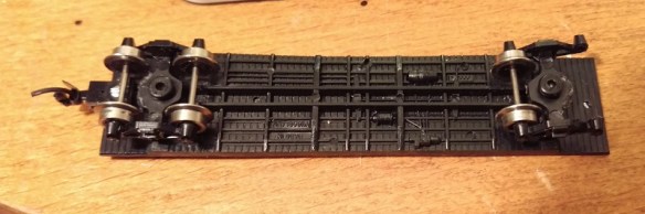
The truck can then be loosely re-fitted, there is no need to push the bolster pin in hard as it will be removed again shortly.

Micro-Trains Body Mount Coupler Fitting 10

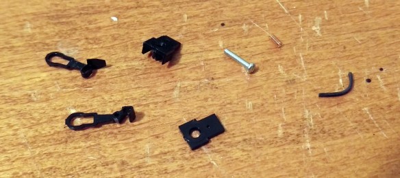
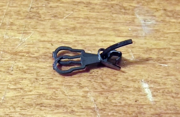
The bulk pack of couplers contains lots of parts but to assemble one coupler you need the five laid out below.  They are the coupler hook and catch plate, coupler box and top plus a spacer, screw, spring and drop pin.

Micro-Trains Body Mount Coupler Fitting 11

Using the craft knife remove the coupler hook and catch plate as well as the coupler box and top from the sprues.  The spacer is the flat part on the right and may be required later so put it to one side.

Micro-Trains Body Mount Coupler Fitting 12

With the parts removed there’s one small thing I like to do before assembling the coupler and that’s to use the file to deburr the top of the drop pin.  This simply makes it fit easily without too much force which can break the coupling hook.  The end that fits into the coupler hook is the longer leg.

Micro-Trains Body Mount Coupler Fitting 13

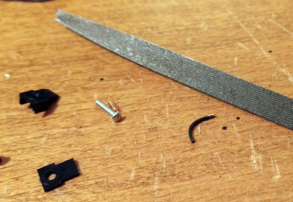
I tend to hold the pin in the tweezers or pliers and run the file on four sides of the pin at 45°.

Micro-Trains Body Mount Coupler Fitting 14

With the pin still in the tweezers or pliers push the filed end into the small hole in the coupling hook.  The pin should be at an angle which is parallel to the side of the hook.  The pin only needs to go through the hook so the end is just poking out of the top.

Micro-Trains Body Mount Coupler Fitting 15

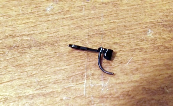
With the pin fitted slide the coupler catch plate over the pin.

Micro-Trains Body Mount Coupler Fitting 16

With the coupler box on its back place the assembled parts over the tube in the box.

Micro-Trains Body Mount Coupler Fitting 17

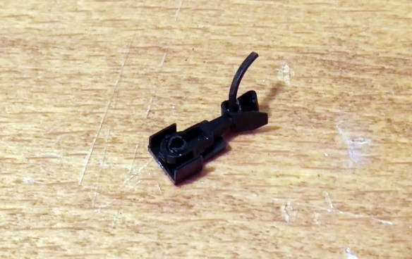
The next part is the most tricky.  There are several ways of doing this but for me I like to use a pair of needle nose tweezers and a watchmaker’s screwdriver.  The risk is that the spring will ping off and, given how small these are, you usually can never find it.  Luckily MT provide several spares in the kit.  I find it’s best to get the spring close to the coupler and almost in the same orientation.  Then carefully compress the spring with the tweezers and place it over the slot between the coupler box tube and parts.  Using the screwdriver push the spring down into place and release the tweezers.

Micro-Trains Body Mount Coupler Fitting 18

Once in, the spring will stay there, but the assembly is very delicate so don’t knock it or the spring may ping out.

Micro-Trains Body Mount Coupler Fitting 19

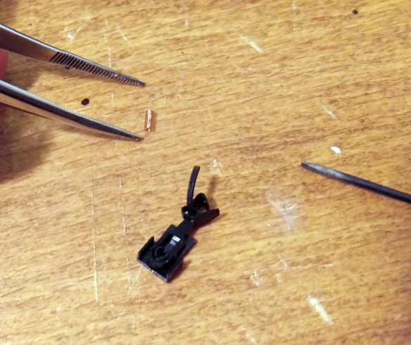
Using the tweezers place the box lid on to the box and press down with your finger.  It should clip into place.  The lid only fits on one way round and the underside has groves to fit onto the box.

Micro-Trains Body Mount Coupler Fitting 20

Once the lid is clipped on the coupling is fairly robust and can be moved about.  Check that the coupling moves in the box and bounces back to the same central position.

Now it is time to fit it to the car chassis.  The particular set I am using are medium length, for a 40 foot box car. A short length might have been better but they will work just as well.

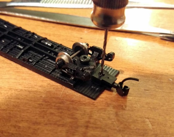
Place the coupling on the underside of the chassis and pass the drill through the box tube.  Once the coupling is as far back as you want it, ensure the truck can rotate and the coupling is centered, and use the drill to mark the chassis.

Micro-Trains Body Mount Coupler Fitting 21

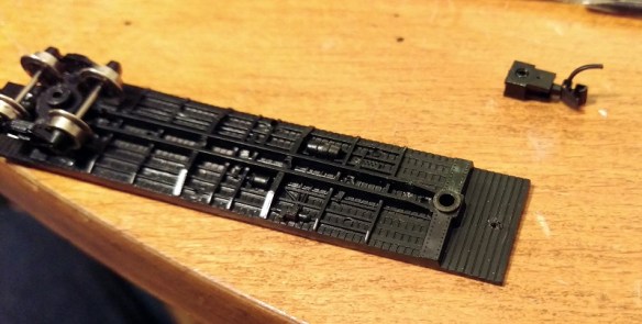
Then remove the coupling and truck so you can easily drill through the chassis.  Depending on the make of the car the distance from the edge will vary, but I tend to find the hole needs to be halfway between the third and forth plank counting from the edge.  As this car has a plastic chassis the metal screw will cut its own thread.  However if the chassis is metal you may want to use the tap that came with the MT tap and drill set to cut a thread in the chassis.

Micro-Trains Body Mount Coupler Fitting 22

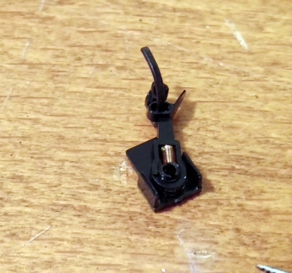
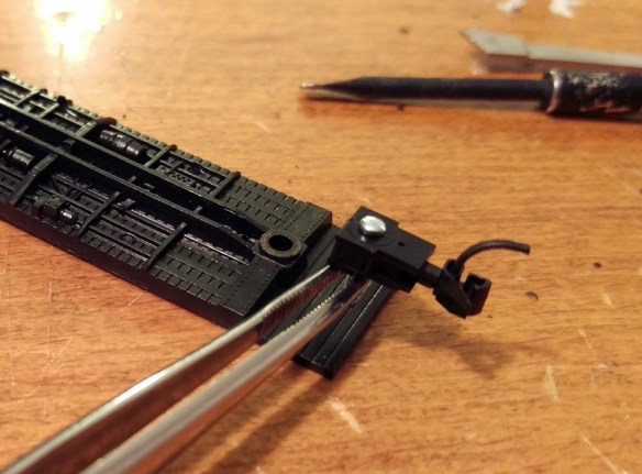
Next push the screw into the coupler box hole from the underside.

Micro-Trains Body Mount Coupler Fitting 23

I find pushing the screw all the way though and holding it with the needle nose tweezers helps keep the screw straight when you start to tighten it up.

Micro-Trains Body Mount Coupler Fitting 24

Once the screw is started you can let go with the tweezers and tighten it up.  Make sure the coupler is square before you fully tighten it. You will notice that the screw is now sticking through the floor of the chassis.  This is not a problem as it will be inside the box car but if your car has a veranda, such as you get on a caboose, or is simply a flat car, you will want to shorten the screw with the side cutters first. Note: you will also need to use a big set of side cutters for this as you may break a modeling pair.

Micro-Trains Body Mount Coupler Fitting 25

The truck can now be installed.  If the truck can rotate freely push the bolster pin in all the way and refit the wheel set.

Micro-Trains Body Mount Coupler Fitting 26

The last thing to do is check the height of the coupler.  Using an MT gauge as shown below this is very easy to do.

Micro-Trains Body Mount Coupler Fitting 27

Simply clip the gauge to the track, shutting off the power first, and test the new coupling with it.  Should the coupling be too high simply unscrew the coupling and add the spacer that we put to one side earlier. This will lower the coupling.  In the unlikely event that the coupling is too low then remove the trucks and add a washer to each; this will raise the whole box car correcting the coupling height.

Micro-Trains Body Mount Coupler Fitting 28

The box car is now ready for service.

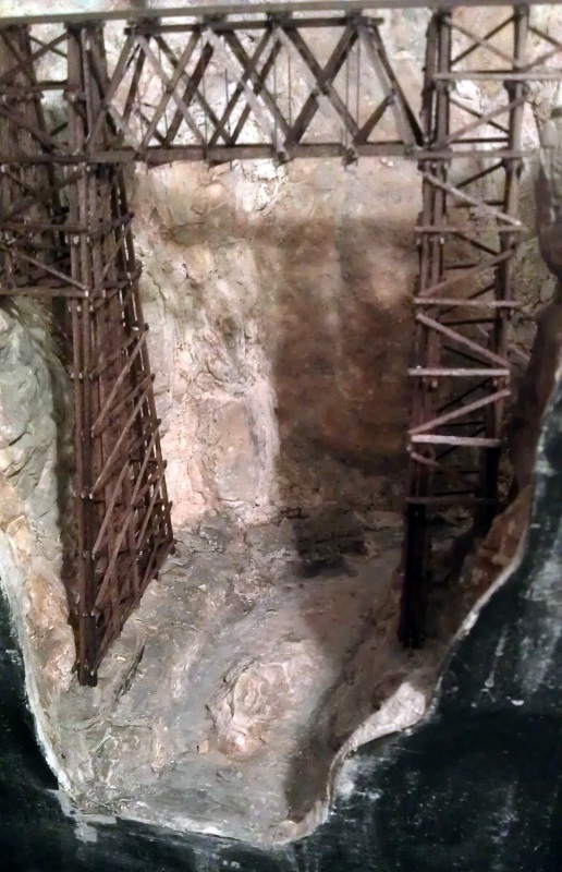
As I said at the beginning the NMRA (BR) Convention is this weekend at Derby, England and I will be there along with my fellow modelers running the N Scale modular layout ‘Solent Summit’, and my new modules will be there.  The convention is open to the public on Sunday and it would be great to meet anyone who is coming along. If you can’t make it I will be giving a full report here in the coming weeks.  This week I will leave you with a taster from my new modules, below is a video of a ‘short’ train crossing the Warsash River on the Warsash Wye trestle.

A Useful Tool for Soldering

One of challenging things about soldering wires onto switches and components is not having enough hands. Trying to hold the soldering iron, wire, switch and solder can be a bit tricky at times so in this post I will share with you a simple tool I have found to help.

I have used this tool for all sorts of things from Seep point motors to Din plugs.   The advantage the tool gives you is it has a firm shell and a soft inner similar to a pin cushion. This allows you to stick or plug the item you need to solder wires to into the tool leaving your hands free to solder on the wires. With items like Din plugs that are small and have lots of wires this is particularly usefully as without the tool the wires you’ve already soldered on will tend to pull the Din plug away from where you need it. The tool will keep the plug in the same place.

This tool is available at just about all local shops, is very inexpensive and comes in a variety of sizes. Although you will have to get a new one on a regular basis I recommend getting a bigger one as the smaller ones tend to roll around too much.

So what is this amazing tool? Well, it’s a potato!

Potato Tool 1

As you can see in the photo below the long bar that is used to throw the points on this Seep point motor has simply been stuck into the potato making it very easy to solder on all the wires. The circular hole patterns are from the Din plugs that were made up earlier.  A smiley faced potato is not a necessity but it can brighten your day!

Potato Tool 3

As I said before it is a good idea to regularly change your potato tool, particularly if it turns green!

We are now only two weeks away from the this years NMRA (BR) convention so it’s back to the modelling for me to get my modules finished in time but after the show I will be back to 3D printing and progressing some of the projects.

Ballasting up to a Trestle or Bridge

As I am now nearing the end of my module build I am concentrating on some of the details that make my modules realistic.  I have already shared with you how I ballast my track and you can read about it here.  In this post I will share with you how I ballast my track up to trestle ends where the ground suddenly drops away.

In the model world the ballast is glued down so there is no problem placing ballast right on the edge of a drop as the glue will hold it in place but in the real world wind, rain run off, train vibration and general movement will cause the ballast to fall of the edge creating a weak spot in the trackage.  Where the ground gently slopes away, as in the image below, this is less of an issue as the ballast will simply form a shoulder; as it does on the sides of the track.

Baslisting at edges 1

However areas where land drops of steeply or as in my case vertically the ballast needs to be contained.  There are all sorts of ways to do this from using concrete to earth banks but as my trestle is made from timber it would make sense that the containing barrier would be made from timber as well.  As you can see in the picture below I have created a C shape where the trestle starts.

Baslisting at edges 2

There would be no timber between the rails because the bridge ties will provide the required barrier.  I have repeated this at all the trestle ends where the land drops away as you can see in the images below.

Baslisting at edges 6 Baslisting at edges 3 Baslisting at edges 4 Baslisting at edges 5

The timber has simply been glued to the scenery using white glue.  Once the glue had dried it was time to add the ballast and using the same techniques as before I ballasted up to all the barriers.

Baslisting at edges 7 Baslisting at edges 8 Baslisting at edges 9 Baslisting at edges 10 Baslisting at edges 11

With the trestle end meeting the land on a gradual slope the ballast simply runs into a shoulder as you can see below.  The end of the trestle is founded on a timber frame full of rock and ballast that has been cut into the bank.

Baslisting at edges 12 Baslisting at edges 13

The overall effect is a well ballasted track section with clean bridge track.

Baslisting at edges 14

The final stage to complete the trestles will be to add the check rails and safe refuges which I will cover in a later post.

Making Talus and Rock Fall for Your Layout

As you may have read in my previous posts I am currently building a pair of modules to form part of the Gosport American Model Railroad Group’s N Scale Layout.  In this post I will share with you a quick and cheap method to make some talus, boulders and general rock debris.

You can buy bags of talus form companies like Woodland Scenics in a variety of sizes but sometimes having a larger variety can be useful.  If, like me, you have cast your own rocks from rock molds (you can read more about doing this here) then it’s likely you have lots of bits of plaster left over.  I tend to fill up my rubber rock molds and this causes plaster to flow over the flat rubber and mold sides.  When I break out the rocks these pieces break off and I collect them in a tray.

Depending on what you want to use your talus or rock debris for will depend on how you color them, but for me I want to simulate fallen rock into my canyon and rock that has been washed down the river in the winter floods.  From reference materiel I have noticed that there is often less difference in the color range of the talus than in the actual rock faces.  This might be because only certain parts of the rock face are crumbling due to the different rock composition so only the softer rock will be in the bottom of the canyon.   Given that my dominant rock colors in the canyon are yellow ocher and burnt umber my talus will be a blend of these two colors.  You can read about my rock painting process here.

So here is my recipe for rock soup!  I start with a tray of plaster bits and crunch them up with my hands until they are roughly the right size.  Then I pour on a bit of burnt umber that has been mixed with water at a ratio of 1 part pigment to 16 parts water.  I give the mixture a stir to move the parts around.

Making Talus 1

The pigment soaks right into the dry plaster parts as you can see in the above photo.  Because I didn’t add a lot of pigment it only soaked into certain faces in a similar way to the leopard spotting I used on my rocks.  Next I add yellow ocher mixed at the same ratio 1 part pigment to 16 parts water.  This time I added a lot more pigment so all the bits get a good soaking, hence the term ‘rock soup’.

Making Talus 2

The rocks in the tray are stirred and shaken up so all surfaces get a good coating and the mixture is left for an hour or so to ensure the rocks get thoroughly saturated.  That way if they are chipped or broken they won’t show through brilliant white.  Once I am happy with the amount of saturation I drain off any excess liquid and leave the rock parts to dry.  This may take a day or so and it is a good idea to give them a stir now and again which will bring the wetter bits to the surface helping them to dry faster.  This processes will also work on Woodland Scenics’ talus as you can see below.  The lower tray is all the plaster debris and is a lighter color because it is a more porous material than the Woodland Scenics’ talus.  However the two will mix together well.

Making Talus 3

The area I am going to be using this on is the bottom of my canyon which you can see in the pictures below.

Making Talus 5

Making Talus 4 Making Talus 6

The river bed has been painted and is ready for some debris.  I start by dropping some of the mixture down the rock faces to see where it lands, also I add clumps in areas that would have caught rocks when the water was flowing at full strength in the winter months.  All the modules on the GAMRG’s layout are set in late summer so the water level will be low.

Making Talus 7 Making Talus 8

Next I use a watered down PVA glue in a spray or mister.  Again Woodland Scenics sell the right glue for this called Scenic Cement but you can make your own.  They also sell the spray bottle but I tend to use a basic one with a removable nozzle purchased from a garden center designed for misting plants.  It is a good idea to have a bowl of water close by so you can put the nozzle in to soak between spraying as it will start to clog up.  Because the mister gently soaks the areas it doesn’t move the rocks about.  I tend to place the talus is several stages giving the area a good soaking of scenic cement between each layer.

Making Talus 9

As you can see below I do mean a good soaking.  The talus is heavier than scenic scatter material and you don’t want it coming off the layout, especially a modular one that will get bumped around between shows.

Making Talus 10

You don’t have to wait for the first layer to dry before adding the next, in fact it is best not to as the new layer will sink into the wet glue adding to the strength.

Making Talus 11

Once you are happy with the amount and overall look give the whole area another good soak with glue and leave it overnight to dry.  Don’t be tempted to touch it until it’s dry as the talus will be very easy to dislodge until the glue has totally set.

Once all the glue has dried it will become clear and leave you with a solid scene that you can add water to or simply leave as is.

Making Talus 14 Making Talus 15 Making Talus 16 Making Talus 17

Making Talus 18

I still need to add some more vegetation at the river edge and add the water itself which I will share with you in another post.

This coming weekend, the 3rd and 4 th of October 2015 I will be at the Fareham RailEX model railway show with part of the GAMRG’s N Scale layout.  The exhibition will be at the Fareham Leisure Centre, Park Ln, Fareham, Hampshire PO16 7JU, UK and you can read more about the show here.

My new modules that I am working on will not be in this show as they still need a bit of work but it would still be nice to see if you are in the area.

Quick & Easy Ways to Ballast Track

Over the years I have tried all sorts of methods to ballast track.  Some have been very time-consuming and some have just looked rubbish.  In this post I will share with you a method I have found to be fairly quick and easy and also gives good results.

Ballasting track is a key part of building a model railroad or railway.  Not only is it necessary for making the track-work look right but, just like the real thing, the ballast holds the track permanently in place.

The current layout which I’m working on is an N Scale modular layout and forms part of the Gosport American Model Railroad Groups ever-growing layout.  This particular module, New Mills,  is a small country halt next to a group set of factories.  The halt is used mostly by the factory workers and small town nearby.  Most of the trains pass without stopping so rather than platforms the tracks outside the halt have been boarded over so passengers can access to the local passenger cars via their steps.  Below is a photo of the left hand end of the module  The main line enters on the left nearest to the front.  It splits into two tracks that pass the station depot and then rejoin each other before leaving from the right hand end.  The third line with the end of a GP38 sat on it is the entrance to the factory sidings.

Balisting Track 1
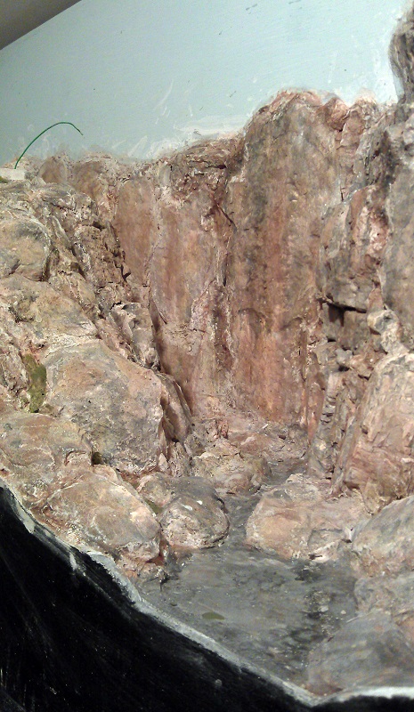
Before I even think about ballasting track I always do lots of running on the layout to make sure everything works okay.  The track is glued down onto a cork road bed which in turn is glued to the module top.  The cork is important for a few reasons which I will cover in a bit.  In the picture above you may have noticed that the track has been weathered.  This is not a necessity but it adds the realism I like to see; railroads are not a clean place.

I have several methods of weathering track.  First there is the spray paint method.  This can be done with an airbrush or aerosol can.  For the bulk of this module I used a grimy brown color aerosol.  Before spraying I removed everything from the module and simply sprayed along the tracks.  Then I quickly wiped the rail heads with a cloth to remove the paint.  Once the paint had dried I also ran over the rail heads with a track rubber to totally remove any paint residue.  Since doing that I have also added a few more bits of track but as I don’t want to risk spraying other stuff now fixed to the module I used a brown wash to weather the rails.

Balisting Track 2

Making a wash from paints is fairly easy but I find this the quickest.  Once the pot is shaken up the wash inside simply paints on.  I tend to roughly brush over the ties and rails then brush again with no wash on the brush.  This removes any excess wash and gives a mixed finish.  As before I wipe the rail heads over with a cloth.  Once you start to weather your track any new sections stand out as you can see in the photo below.

Balisting Track 3

Once all the track is weathered and had a chance to dry I tested it by running a few trains. Then it’s time to add some ballast.  Ballast comes in all sizes and colors.  For our group modules we stick to the same make and colour for continuity which is Woodland Scenic Fine Gray ballast.

On the real railroad the track is laid on top of a deep bed of ballast, then more is poured on top and packed or tamped down tightly around the ties.  Because the track is on a bed of ballast it is easy for the track gang to raise or lower the track to ensure smoothness as well as adding any special enhancements such as super elevations on corners.  Also this means the track is raised off the floor and the ballast acts as a natural soak away to stop water from flooding the tracks. Given most track ties were timber this was a good thing.

On the model railroad adding a bed of ballast is not very practical so we use a layer of cork.  Then when the ballast is poured on and covers the cork it will look like a nice deep bed and form the correct shoulder or slope on either side.

To start with I simply pour the ballast on in the right area trying to gauge the right amount.  Then using my finger I run it along the center of the tracks spreading the ballast evenly around.

Balisting Track 4

Then to get the right finish I use a small paint brush to carefully move the blast around.  This works for most of it but there will always be the odd bit that gets in the wrong place.

Balisting Track 5

The main area to worry about is the inside of the rail as this needs to be kept clear for the wheel flanges to run in.  I find the best tool for cleaning this is a small watchmakers screwdriver which can be run along the inside of the rails and knocks off any stray ballast.

Balisting Track 6

The area in the photo above is a little thick with ballast by intention.  Normally ballast is leveled off just below the tops of the ties and the excess is moved down the line.  However at that particular section the track is flanked at both ends by a boarded walkway and roadway so the excess ballast tends to get left there and forms a ridge down the center of the track.  On the other side of the roadway the ballast starts to get a bit thinner as the track crew have more room to spread out the ballast.

Balisting Track 7

When it comes to turnouts it’s okay to add ballasts around the rails but the gaps between the check rails and inside the frog (the V shape in the middle) must be kept clear.  Again the small screwdriver is ideal for this.  It is also important to keep the moving areas free so keep moving the turnout blades thoughout the process.

Balisting Track 8

Once the ballast is in the right place I use an old freight car with big flanges as a tester.  I run it up and down to make sure there is no ballasts where it should not be.  I also change the turnouts.  Note: if you have solenoid operated turnouts the sudden bang will dislodge the ballasts and can also bounce it into areas you don’t want it.  Although this can be useful for removing it if you have got some in the turnout blades.

Once all the turnouts can be thrown, manually, and the test car runs up and down, it’s time to stick the ballast down.  For this I’m using a product from Noch that was recommended to me.

Balisting Track 9

I have used other ballast glues and made my own in the past but this product works better than any of them.  The dispensing nozzle allows you to carefully and accurately drip or drizzle the glue where you need it and it doesn’t cause any lift in the ballast.  By ‘lift’ mean the ballast raising up onto liquid glue that has not soaked into the ballast.  It does not bubble or flow along the ballast causing washouts; it simply runs in.  In the picture below I started in the center of the track from the left, and although I was a little heavy-handed the ballast glue still soaked in anway.

Balisting Track 10

I then worked around the tracks covering all the ballast.

Balisting Track 11

Before the glue has a chance to dry I did one more test with an old freight car. This is why I use an old freight car as you get glue on the wheels. Then I left it overnight to set fully.  The next day all the ballast was dry and any surplus could be picked up with a vacuum cleaner.  Because the rail heads might have been covered in the glue I used the track rubber again to brighten them all up so I could do a proper test with a loco.

Balisting Track 12

The next step, which I still have to do, is to weather the ballast.  Out on the main line the ballast would be fairly clean but at the ends of a station area like this there would be coal, oil, grease and diesel spills where locomotives would have been stood.

BalistingTrack 13

You may also be wondering why I haven’t ballasted the track in the industrial area?  Well, this track work is under the obligation of the factory owner to maintain, not the railroad, and the ballast will be lower and dirtier, not to mention full of weeds at the ends of the tracks. To do this I need to mix up some ballast with other products and I will share that with you in a later post.

Repairing an N Scale Minitrix Steamer

The German firm Minitrix, now owned by Markin, used to produce a range of US and UK steamers as well as their native German locomotives.  Most of these early models date back to the 1970s and are still running strong.  However there are a few parts that are prone to breaking and in this post I will share with you how to repair the crank pin on a Britannia class locomotive.

Minitrix used the same chassis or a variation of the chassis on a variety of locomotives.  In the US it was the 4-6-2 K4 and 2-10-0 Decopod.  In the UK it was the 4-6-2 7P Britannia, 4-6-2 A3, 4-6-2 A4 & 2-10-0 9F class engines.  These all had metal side rods, drive rods and eccentric cranks but the eccentric pin that holds it all together is plastic.  And it’s this part that has been known to break. If you look at the model in the picture below I have circled the crank pin in red. The side rod connects all three driving wheels together and is the nearest to the wheel.  The connecting rod or main rod is fixed to the center wheel and runs into the cylinder.  The crank pin holds the connecting road and side rod to the center wheel.  The eccentric rod connects to the cranked end of the pin and drives the valve gear in the cylinder.

Minitrix Crank Pin 1

The crank pin is designed so that the side rod and connecting rod can easily rotate without binding on the pin but are also held in place. So you can see how this works I have modeled the crank pins below.  The square shaft on the end of the pin fits into the wheel.  Because it’s square this will ensure it will rotate with the wheel. The side rod and connecting rod fit over the round section and are held in place by the wheel and cranked top.  The holes in the side and connecting rods are larger than the pin to allow free moment.

N Scale Minitrix Crank pin

What normally happens is the metal rod assembly becomes jammed and the weakest point is the plastic crank pin. The pin breaks where the round section meets the square section and falls out.  The connecting rod then flails about and can become bent.  With this 4-6-2 that is exactly what has happened, although luckily the connecting rod wasn’t bent.

Minitrix Crank Pin 2

So to fix this engine the first thing needed is a new crank pin.  Spare parts for these engines ran out years ago so my next option is to 3D print one.   I printed some using the 3D model above in Shapeways Frosted Extreme Detail material.  It will also print in their Frosted Ultra Detail material.

Minitrix Crank Pin 3

Next the old square section on the crank pin needs to be removed.  For this I used a small drill in a pin vice as you can see below.  I selected a drill that was a bit smaller than the pin.  Once I had drilled through the pin the remaining materiel was so thin and weak it pulled out with a pair or tweezers.  You can see the remains of the pin under the new one.

Minitrix Crank Pin 4

In the image below you can see the old and new parts next to each other.  The old crank pin is connected to the eccentric rod by a metal pin which has a flared end and cannot easily be removed.  One option is to cut off the old plastic crank and un-flare the end of pin hoping to fit it into the new one.  However that is very hard to do.

Minitrix Crank Pin 5

To make this job easier I did cut off the old plastic crank but I did not un-flare the pin.  Instead, using a very sharp craft knife, I cut through the loop on the end of the new crank pin.  This then forms a C shape although the two ends still touch.  Carefully spreading the new C shape I was able to push it over the metal pin as you can see below.

Minitrix Crank Pin 6

The connecting road and eccentric rod were then refitted to the loco.

Minitrix Crank Pin 7

The new crank pin simply push-fits into the driving wheel, ensuring it passes through the hole in the connection and side rods.

Minitrix Crank Pin 8

It is important to make sure the crank pin is pointing in the right direction, which is towards the center of the wheel.

Minitrix Crank Pin 9 Minitrix Crank Pin 10

The next part is to test the the new assembly and what could be better than running it on a layout.  Below is short video of the engine running demonstrating that the new crank pin works perfectly.

The rocking motion is caused by the traction tires as the loco is supposed to be moving.

The last thing to do is to add some silver paint to the new crank pin to help blend it in.  It’s best to put on as little as possible as you don’t want to paint the parts together or cause a bind.

Minitrix Crank Pin 11

A pack of four replacement crank pins is available from Shapeways here.

Alternatively if you would like this repair made to your locomotive for you, you can contact me though the contact page or directly at jamestrainparts@yahoo.co.uk and we can arrange to get it done.