Making a DCC Bus for Your Model Railroad

I have recently been helping a friend build a large OO Scale layout and one of the questions I’m regularly asked is ‘How do I make a robust and reliable DCC Bus?’ In this post I’ll share with you what I’ve done for him.

For those wondering why we need a DCC Bus or what is a DCC Bus, I will explain.  Traditionally model railroads have been powered using DC controllers and control panels with switches to turn sections on and off.  The advantage of this is the wire going to each section need only be capable of powering the train in operation.  Often telephone exchange wire or simple hook-up wire is used as it is cheap and can handle the low current draw over long distances.  However with DCC all of the track is powered at the same time and the more trains you run, the higher the current draw through the wire. Electricity always takes the path of least resistance and this could mean all the power for the layout could end up going down one wire.  If a small wire is used this can lead to loss of power or in worst cases, melted wires, which could lead to fire.

There are several ways to resolve this.  One option is to solder all the rails together and feed them close to the DCC controller but this leads to problems with expansion and contraction in different times of year.  This is not possible with modular layouts and sometimes it’s simply not possible as you need to add breaks at turnouts to prevent shorts.

Another option is to simply use big wires everywhere. However this is very cumbersome, expensive and bulky. Soldering big wires also takes more heat so when it comes to connecting them to the track there’s a bigger risk of meting the plastic ties.

The best option is to have a DCC Bus which consists of a pair of big wires that run around your layout under the base board.  Then use small hook-up wire as ‘droppers’ running from the track to the DCC bus.  It’s also recommended to have droppers for every section of track; that way you’re not relying on rail joiners to transfer current.

So what actual wire should you use?  Well, there’s no specific size but I try to stick to these American Wire Gages and colours.

DC/DCC Bus                         Red and Black                                     13 AWG

Track Feeders                       Red & Black – Under 9 inches             24 AWG

Track Feeders                       Red & Black – Over 9 inches               20 AWG

Frog Feed (For Turnouts)     Green                                                  24 AWG

A 13 AWG wire comes in all sorts of types but I have a good supply of thick six strand cable so that’s what I use.  It has good insulation and although flexible it tends to stay where you bend it.

One thing to avoid when making a DCC Bus is to limit the number of breaks and connections in the wire.  Breaks can cause resistance and bad electrical transfer.  For example, if you are using a high strand count wire and suitcase connectors (which cut into the wire) to join on the feeders; this is a bad idea.  At each connection a strand or two is broken and over the length of the cable the integrity can be affected.  Also, if the cable is split and joined together again at every feeder location with a chock-block, or similar connector, this can add lots of potential bad connections into the bus.

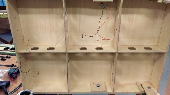
To show you how I avoid all the issues above I’m going to use one of the smaller sections of the layout as an example.  Below you can see the underside  of the module with the track feeders coming through the board.  As the modules are being built away from my friend’s house the DCC Bus will be soldered together once installed.  If I was building it in place I would just use a continuous wire.

DCC Bus 1

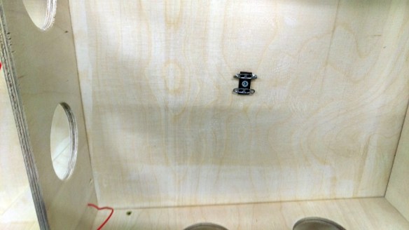
I use Tag Strips, as pictured below.  These have been cut into lengths of three strips.

DCC Bus 2

The strips are held in place simply by bent sections of metal and, by squeezing these together with a pair of pliers, the middle strip can be removed.

DCC Bus 3

This allows the section of Tag Strip to be screwed to the underside of the module.

DCC Bus 4

I put a Tag Strip at each end of the module and, as you will see later, at any point where feeders come through the base board.

DCC Bus 5

Then I feed the DCC Bus cable through the module and, making sure there’s enough cable to reach the next board, strip back some of the insulation.

DCC Bus 6

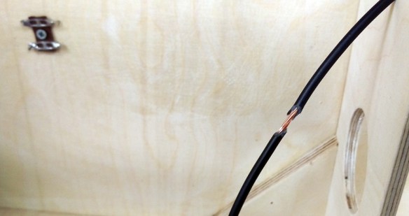
Then I wrap about three inches of solder around the bare wire.

DCC Bus 7

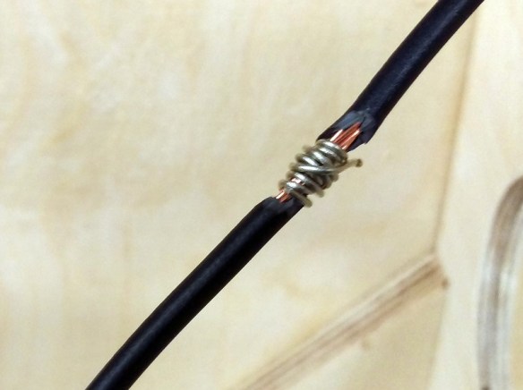
The wire is then bent into a U shape.

DCC Bus 8

Then the solder is melted into the wire with the iron.  As the wire is thick it takes a lot of heat but leaves the shape solid and the wire is still continuous.

DCC Bus 9

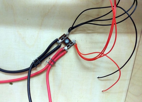
I then tin the Tag Strip and place the soldered U section under the Tag Strip.  Then using the iron I heat up the strip and wire so all the solder flows together forming a solid joint.

DCC Bus 10

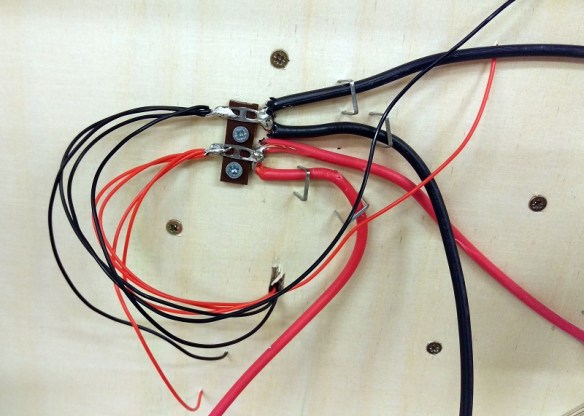
I repeat this with both wires at all Tag Strip locations and staple the wire to the module.

DCC Bus 11

The droppers are then soldered to the other sides of the Tag Strips.

DCC Bus 13

And that completes the DCC Bus under this small board.

DCC Bus 12

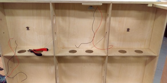
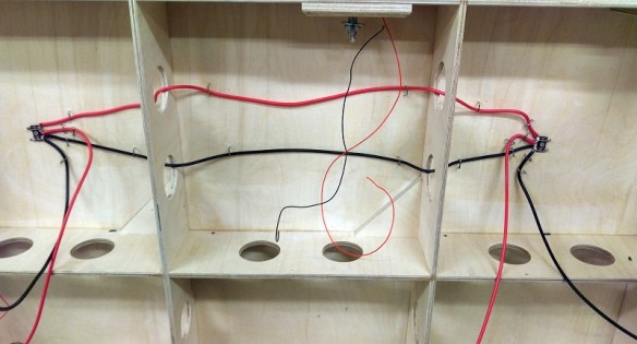
Larger boards with lots more droppers are just as easy with the Tag Strip; connecting them all is simple as you can see below and if more need to be added at a later date they can simply be soldered on.

DCC Bus 14

This board had several Tag Strips in the middle of the board and again the DCC Bus is continuous without any breaks in the wires.

DCC Bus 15

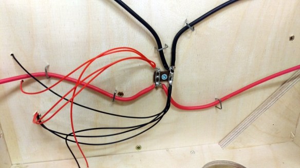
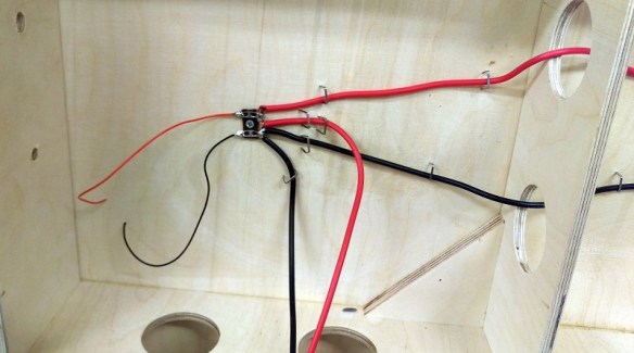
Because the wire is nice and stiff it stays in place and can easily be held there with a few staples.  Below is another section of DCC Bus at the end of a module.

DCC Bus 16

I do have a few suggestions that might help when making the DCC Bus:

Each time you connect a set of feeder wires to a Tag Strip use a volt meter to do a continuity check between the red and black wires.  That way if a section of track hasn’t been cut properly at a turnout or point or there’s some other short issue it will always be located at the last wire you connected.  Otherwise when you finish a whole board and there’s a short it can take ages to find and may end up having to undo all your work.

When you bend the main DCC Bus wire into a U shape, don’t solder the wire first as you won’t be able to bend it.

When you heat up the Tag Strip to connect the DCC Bus wire make sure it’s a good connection and that the solder runs together otherwise you could have a dry joint that will add resistance or lack of connection into the system.

Make sure your droppers are a sensible length, if they’re too short it means you’ll need more Tag Strip locations.

When running the bus wires try to keep them apart by a few inches; this will eliminate any issues caused by induction.  This can have tiny effects on the DCC signals.

And lastly, double-check you have enough length at the ends your modules to join the DCC Bus together.

I find by doing all of this I end up with a strong bulletproof wiring system which leads to well running trains.

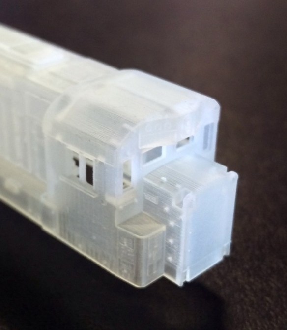
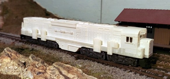
In next week’s post I will have some more to share with you about my Alco C-855 project.

Spring Is Here

It’s been a nice weekend and it feels like Spring really is around the corner and the exhibition season is getting underway. So with that in mind I thought I would use this week’s post to share with you some of the exhibitions I will be at with the Gosport American Model Railroad Group’s layout, ‘Solent Summit’.

Fordingbridge Model Railway Exhibition on Saturday 16 April 2016.

This one-day show hosted by the The Rotary Club of Fordingbridge will be held at the Avonway Community Centre, 6 Shaftesbury Street, Fordingbridge, Hampshire, SP6 1JF, UK.

You can read more abou the show here.

‘Modelex 2016’ Model Railway Exhibition on Saturday 3rd and Sunday 4th September 2016.

This two-day show hosted by the Andover Model Railway Club will be held at the John Hanson Community School, Floral Way, Andover, Hants, SP10 3PB, UK.

You can read more about the show here.

Poole Model Railway Exhibition on Sunday 6th November 2016.

This one-day show hosted by the Poole & District Model Railway Society will be held at The Poole Grammar School, Gravel Hill, Poole, Dorset, BH17 9JU, UK.

You can read more about the show here.

‘Tolworth Showtrain’ Model Railway Exhibition on Saturday 12th and Sunday 13th November 2016.

This two-day show hosted by the Hampton Court Model Railway Society will be held at the Tolworth Recreation Centre, Fullers Way North, Tolworth, Surrey KT6 7LQ, UK.

You can read more about the show here.

So if you are in the area and fancy coming along please come and find me and say hello.

Not wanting to leave you without any trains to look at this week here is a link to a short train video taken at a club running meet this weekend.

D&RGW GP60s and a 2-8-4 Berkshire battling through Solent Summit Station with a long freight.

A New Pilot for an N Scale EMD DD35

My N Scale kit for Electro Motive Division’s DD35 locomotive uses Bachmann’s massive EMD DDA40X chassis, after some shortening.  But as there’s something not quite right about the pilot on the Bachmann model, in this post I will share with you my designs to add a new body-mounted pilot to the DD35.

All of the real EMD ‘DD’ locomotives use four axle trucks which rotate under the chassis. The pilot, which holds the coupling and multiple unit connections, is part of the main chassis, or body, of the locomotive.  This means that as the locomotive runs around a curve the truck rotates but the pilots remains square to the body.  This is done so the load from the coupling is transferred through the chassis and not through the truck mounting. In this image, from Railpictures taken by Tom Farence, you can see the steps and pilot area are square to the body even though the loco is on the bend.

Bachmann’s model of the DDA40X has the pilot attached to the truck causing it to swing out from under the body on curves, as you can see below in this image of a DD35 between a GP38 and an SD35.

DD35 & Friends 4

This also creates a gap between the steps and the body which is, and looks, un-prototypical.  You can see the steps in the image below disappearing under the shell.

SP DD35 9902 8

So why is the pilot located on the truck? Well Bachmann did it for a good reason.  Because the DDA40X locomotive is so long, without the pilots being on the truck it simply wouldn’t be able to navigate the tight curves, which many of us have on our model railroads, without pulling any connected cars off the track.  Curves on prototypical railroads have a much larger radius and they don’t suffer from this issue. The Bachmann DDA40X can actually traverse some very tight curves but it does look odd doing it.

However there are a few modelers that have the luxury of large minimum radius curves on their layouts and have requested a modification be made to my DD35 kit.  Because I already offer the kit in powered and dummy forms using the same shell I didn’t want to created a whole new shell just for this and, luckily, there is a solution.  The dummy DD35 kit, as pictured below, comes with 3D printed trucks that include a pilot.

DD35 Dummy Pilot

The truck and pilot behave in the same manner as the Bachmann one on the powered chassis and have the same appearance so you can run a powered and dummy unit together.

By extending the pilot section up to meet the underside of the 3D printed dummy chassis or the Bachmann metal chassis, the new pilot can be fixed directly to the body, leaving the trucks free to rotate.

DD35 Dummy Pilot 2

The new pilot section, as pictured below, has been shaped so it will fit the sloping 3D printed dummy chassis or the Bachmann metal chassis, and it has the same mount for a Micro-Trains body mount coupler.

DD35 Dummy Pilot 4

The MU hoses are printed as part of the pilot but can easily be cut off with a craft knife or sanded off if you prefer to fit etched brass ones.

The new pilots are available in two packs.

One pair of N Scale EMD DD35 body mount pilots

Two pairs of N Scale EMD DD35 body mount pilots

Please remember when fitting your N Scale DD35 with a body mounted pilot and coupling it will increase the minimum radius that your locomotive can navigate.  If you are unsure if this will work for you, position your DD35 over your tightest curve and see where the nose of the body swings out to.  If it is outside the sensible condition to be able to couple up to a another car or locomotive then your radius is too small.

I will also be making a similar pilot available for the N Scale EMD DDA40X which I’ll share with you soon.

A New Video Gallery for the Website

With all the excitement of my newly released Alco C-855, which you can find here, I have decided to make this week’s post nice and short.

I have lots of videos on my site; sharing with you what I’m doing and the exhibitions I’ve been to, but sometimes I simply take videos of my, or other club members’, trains running on our layouts and I don’t always have a reason to post about it in the blog.

So I have created a new section in the gallery called ‘Video Gallery’.  In here you will find videos of our model trains listed by road and date.  Some of the older ones are a bit jumpy but they do get better.  When you click on a link it will open in a new full screen window where you can play the video.

As I take more I will add them to the gallery and on the home page there’s a new section on the right-hand side called ‘Latest Gallery Video’ so you can easily see when I’ve added something new.  The link will also take you directly to the video.

The ‘Video Gallery’ can be accessed by selecting ‘Gallery’ from the drop down menu above.

An Alco C-855 for N Scale Part 2

As promised earlier this week in my usual Monday night post, I am adding this extra post to let you know that the N Scale Alco C-855 kit is now available on Shapeways.  I have finished all the etched brass testing and everything fits perfectly.

You can get the Alco C-855 kit here.  Don’t for get the chassis extenders and the etched brass Additions.

So now it’s back to the drawing board for the C-855B.


An Alco C-855 for N Scale

In this weeks post I will share with you the first N Scale 3D printed Alco C-855 and all the accompanied parts.  If you want to read more about the history of this project click here and it will open a new page listing all my posts about it.

This model has been in the pipeline for a few years, so as you can imagine, I was very excited when last week the first test print arrived from Shapeways, and I must say I am very pleased with it.  Below you can see all the parts as Shapeways delivered them.

Alco C-855 First Print 1

At the back is the main shell; all in one piece.  The eight parts in front and to the left are the sand boxes, which fix onto the sides.  Each sand box has a locating peg which fixes into a hole on the side of the shell.  Next to the sand boxes are the crew and control consoles for the cab interior.  Below the two crew is a square plug which acts as a screw mount for holding the fuel tank on.  Next to the crew are the horns, these again have a simple peg which fixes into a hole in the shell.  The fuel tank is next to the horns and the two round parts are the drive shaft extenders.  The final two parts at the bottom are the 3D printed stainless steel chassis extenders.  The plastic parts have been printed in Shapeways’ Frosted Ultra Detail.  Although the Frosted Extreme Detail has a smaller layer thickness than FUD giving an even better finish, this was a test print and I wanted to see how it would come out before going to the best quality.  But even in FUD the details are clear and smooth and I will be very happy with this as an actual model.  Here are some close-ups of some of the detail

Alco C-855 First Print 2 Alco C-855 First Print 3

As normal with parts printed in FUD or FXD they need to be cleaned to remove the waxy residue, so after a rinse of in warm soapy water they spent 24 hours submerged in Goo Gone.

While the parts where getting cleaned I prepared another chassis.  I already had one extended chassis but as I have made some improvements to the chassis extenders I wanted to make up another.  As I have already covered this procedure in a previous post, which can be found here, I will only show the differences today.  I will be making a downloadable PDF available with full instructions soon.

As before I started with a standard Con-Cor U50/Turbine chassis.

Alco C-855 First Print 4

The new  chassis extenders have been tweaked in several places but the most obvious is the introduction of a forward arrow on both parts, this should help with orientation in the chassis.

Alco C-855 First Print 5 Alco C-855 First Print 6

The top section should be done first.  And this simply means removed the section highlighted below.  I used a cutting disc in a Dremel type tool.

Alco C-855 First Print 7
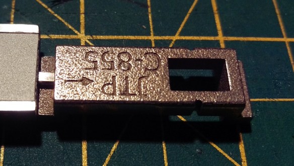
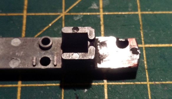
The three parts where then glued together.  The key is to make sure the dog leg part of the chassis extender is flush with the underside of the remaining parts.  There should be a small gap at the location where you made the cut.  That way the chassis will be the correct length and it will be easer to keep it square.

Alco C-855 First Print 8

Unlike last time, I also need to make some cuts at the front because the body of the locomotive is narrow below of the cab.  The two wings need to be cut off as shown below.

Alco C-855 First Print 9

Also two notches need to be made.  I will give the sizes of these in the downloadable PDF.  The top notch ended up a bit larger than I had hoped because of the screw hole.  You could simply cut it all off but I want to keep as much weight as possible.

Alco C-855 First Print 10

As I pointed out earlier there is a plastic square plug used to screw in the fuel tank.

Alco C-855 First Print 11

This simply fits into the square hole in the bottom chassis extender.

Alco C-855 First Print 12

It will be held in by the motor and when you screw on the fuel tank, using the same screw from the U50/Turbine fuel tank, it will pull tight.

Alco C-855 First Print 13

With the bottom chassis section it is important to cut it as close to the parts that hang down as possible.  Other wise you may end up with a gap in the chassis frame. Indicated below is the section to be removed.

Alco C-855 First Print 14

Once fully assembled it should look like this.

Alco C-855 First Print 15

My C-855s will be DCC so I have installed a decoder in the space at the rear of the locomotive.

Alco C-855 First Print 16

The next step was to test fit the shell.  In the photo above you can see a square hole at the front of the fuel tank.  Inside the shell is a tapered peg so as the shell slides onto the chassis the shell will spread untill the peg pops into the hole holding it tight.

Alco C-855 First Print 17

The shell is nice fit and once the pegs locate into the fuel tank you can comfortably pick it up by the shell and it wont fall apart.

One of the identifying details on the C-855 is the large sand boxes on the side and because of the locating pegs these can easily be clipped into place.  I have made them a separate part to make it easer to paint the model.  In the photo below they are not glued in place but simple press fitted.

Alco C-855 First Print 18

But as great as the loco now looks there are still lots of parts missing.  And today I took delivery of the first batch of etched brass Additions for this loco.

Alco C-855 First Print 19

As I am going to paint the loco a lot of the parts are not ready to go on yet, plus I only got them today, but to give you and idea of what the finished loco will look like here are some picture with some of the brass Additions loosely fitted.

Alco C-855 First Print 20

Because just about all the brass Additions have mounting holes or slots they should be very easy to install.  The handrails drop into the top of the sand boxes which makes them easy to align.  There are a lot more parts to be added and some, like the ladders, can’t be shown yet as the handrails need to be fixed properly first but as you can see from the image below even the windscreen wipers have mounting holes.  It has swung to its natural hanging position but once glued in, it will line up with the left of the window frame.

Alco C-855 First Print 21

I want to do a few checks to make sure everything is where it should be for all the brass Additions and then the shell will be made available on Shapeways. I think that will happen in the next few days.  The chassis extenders are available now and can be ordered in sets of one, two or three by clicking on the links below.

Set of one C-855 chassis extenders.

Set of two C-855 chassis extenders.

Set of three C-855 chassis extenders.

There is an option to print the chassis extenders in WS&F and FUD which are both cheaper than the stainless steel but you will lose a lot of weight and please note: I have not tested them in these materials.

Although I normally post on a Monday I will do an extra post this week to let you know when the C-855 body and parts are ready as I know several of you are keen to get them.  If you order the chassis extenders now you can add the shell to your order at Shapeways without paying for shipping twice, as long as you do it in good time.  I also have brass Additions in stock, these are £6 GBP each.  Please contact me though contact page or email me if you would like to order some.

The next step, apart from painting and finishing the C-855, is to finish drawing the C-855B.  The chassis will be exactly the same so the extenders will be need for that too.  I will also be drawing a dummy chassis for both locos and will be sharing that with you soon.