The Best Way to Weather My Stock

In last weeks post I promised to share with you some of my newly-weathered stock so that is exactly what I’m going to do.

I have a range of rolling stock from different manufacturers and a lot of the freight cars,  although they are very nice, some do seem a bit brightly coloured.  To be fair a lot of them would have been this way when they rolled out of the factory for the fist time.  But after spending some time of the rails everything gets dirty,  and even rusty as they get older.

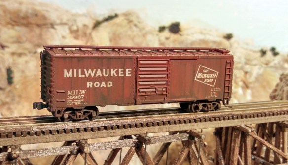
I think they should look more like this.

Weathered Stock 11

Here are some closeups shots.

Weathered Stock 6

Weathered Stock 5

The next three where identical before weathering.

Weathered Stock 4

Weathered Stock 3

Weathered Stock 1Weathered Stock 7

Weathered Stock 2 
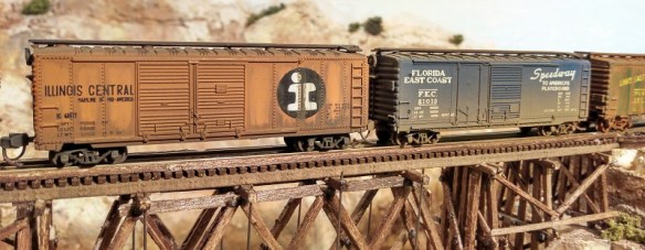
As a comparison; below is a factory weathered freight car, on the left, alongside my weathered freight cars.

Weathered Stock 8

One of the things I didn’t like about the factory weathered freight car was the trucks, they look too shiny and new compared to the rest.

Weathered Stock 9

Below is a short video showing a train passing with regular stock followed by a train with the new weathered stock.

So how did I do this?  Well given that time is precious, as those waiting for projects to be draw will appreciate, I’ve found the best solution.  Get somebody else to do it!

These were all airbrushed by Model Railway Solutions. MRS provide all sorts of modeling solutions from flat pack baseboard construction, all the way up to complete model railways built to exhibition standards.

The weathering service is very reasonable and they are happy to work with large batch projects which can reduce the shipping costs when sending models from overseas.

Here are some of the other models that were on the work bench when I collected this batch.

This is an N gauge southern region Merchant Navy class locomotive.

Weathered Stock 14 Weathered Stock 15 Weathered Stock 16

This is a OO Gauge 9F made by Hornby.

Weathered Stock 17

Although the main body is dull and dirty the running gear looks wet and oily, these photos don’t do the locomotive justice.

Weathered Stock 18

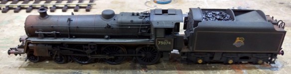
Here is a BR Standard Class 4MT made by bachmann.

Weathered Stock 19 Weathered Stock 20

I liked the rusted areas around the tender water filling area.

Weathered Stock 21

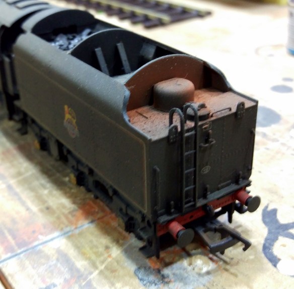
The real coal in the tender was also added by MRS.

Weathered Stock 22

Coaches also get dirty and below is a OO Gauge collett coach made by Hornby which has also had the air brush treatment.

Weathered Stock 27

And to pull a train of these coaches, what could be better than a GWR Castle class. Again this OO gauge model was made by Hornby and is now in a typical representation of what it would have looked like when these engines where nearing the end of their life. Weathered Stock 29

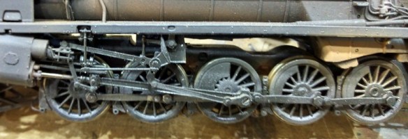
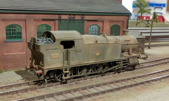
Of course freight engines where not looked after anywhere near as well as the passenger locos.  Below is an image of a brand new OO Gauge Hornby 2-8-0.

Hornby 2-8-0

MRS spent some time on it and now it look like this.

Weathered Stock 23 Weathered Stock 24

It still runs as smooth as silk but in this condition you can just imagine it has seen many years of use.

Weathered Stock 25

MRS are happy to be contacted by phone or email and both can be found on there website.  Alternatively you can always drop me a message through my contact page and will be happy to talk to them for you.

Electric Motors and Measuring Stall Currents

Often when I am writing about fitting DCC decoders into locomotives I recommend checking the stall current of the motor.  This should be done to make sure the DCC decoder is up to the job.  However I don’t think I have ever fully explained what this means or how to do it so this week’s post will be about exactly that.

Although DCC system supply a form of alternating current, AC, to the track, the electric motor still runs on direct current, DC.  The DCC decoder will convert the AC into DC using a bridge rectifier and supply the correct amount of voltage to make the motor run at the desired speed.  The higher the voltage, the faster the motor runs.  But what about power?  Simply adding more volts alone will not make the locomotive pull a heavier train.  The answer is current. Every electrical device will draw a current which is measured in amps.

Without going too deep into the mathematics behind all of this, current can be explained in a simple equation: the current ‘I’ in amps (A) is equal to the voltage ‘V’ in volts (V) divided by the resistance ‘R’ in ohms (Ω):

Ohm's Law

So, for example, a train running at slow speed, light engine, will have little resistance and may pull 0.2 amp at 6 volts.  Add a heavy train and the motor now has a lot of resistance so it might pull 0.5 amp but still at 6 volts.  As the resistance is increased, adding more freight cars for example, the current draw will also increase until one of two things will happen.  Firstly, and most commonly with N Scale, the locomotive will start to wheel spin as the resistance, in this case friction, between the wheels and the track is weaker than the motor.  The current draw will drop off but the train won’t be going anywhere.  Secondly, the motor will stall.  This means that the motor will draw as much current as it can but simply cannot spin anymore because the train is too heavy and the friction between the wheels and rail is too great.  This might happen if you have good traction tires on your wheels or something gets stuck in the gears.  When a motor stalls like this the current draw will peak sometimes up to and over 1 amp and it’s this that can damage a decoder.

The electrical components in a DCC decoder are only designed to take a certain amount of amps through all the tiny wires and connections.  This is because high amperage draws cause a variety of issues, one is heat. This is normally dealt with by using bigger wires and components.

All DCC decoder manufacturers state what their decoders are capable of handling.  For example, below is the instruction manual for a Digitrax SDN136PS sound decoder; I put these into my C-855 locomotives.

DC Stall Test 1

The manual says the chip has a 1.0 Amp /2.0 Amp peak capacity.  This means that the normal operating current draw that this chip can sustain is 1.0 amp and for short periods it can sustain a peak of 2.0 amps. Anything over this will damage the decoder or cause it to shut down.

So how do you measure the stall current to see if your chosen decoder will work with your motor? Well, you’ll need some wire, a DC controller and one of these…

DC Stall Test 2

It’s a multi-meter.  It doesn’t have to be an expensive one; it simply has to have the ability to measure current up to at least 2 amps.  This particular one will measure up to 10 amps, so it will do nicely.  The red wire is plunged into the hole marked 10A and the black into the common.  The dial is rotated to the red 10A marker and you can see below it’s reading 0.00 amps.  It’s now ready to use.

DC Stall Test 3

I should point out – DO NOT do this with a locomotive that has a DCC decoder already installed as you may do damage to the decoder.

Using a section of spare track which is not connected to anything else, connect one wire from your DC controller to one rail.  Connect the other DC controller wire to the black multi-meter wire.  Lastly, connect the red multi-meter wire to the other rail.  Now when you put a locomotive on the track and run it up and down, the multi-meter will display the current the motor is drawing.  Normally with DC locomotives this will also include any current draw from lights as well.  Remember the max current draw of the decoder will be for everything, not just the motor.

The main reason for doing all this was to measure the stall current of the motor and to do that you will need to find a way to stop it spinning when it’s under full power, i.e. full throttle on your DC controller.  With N Scale this can often simply be done by removing the locomotive shell and stopping the motor with your fingers, although I would not recommend doing this with larger HO and O scale engines as they have some big motors!

With the motor ‘frozen’ between your fingers and the power on, the multi-meter should be reading the max current draw from the motor.  If this value is higher than the manufacturer recommends for the decoder then it will not be safe to use it.

Normally with N Scale locos the stall current is about 0.6 to 0.7 amps and with a few LEDs it may go up to 0.9.  Add sound and it could be up to 1.5 amps but as long as that is below the manufacturers specification than it’s still safe.

This has been useful when I’ve wanted to run two motors from one decoder. For example, my Bachmann F7s, which you can read about here.  They have two decoders for four locos.

Bacmann F7 DCC Install 36

Next week I’m going to share with you some of my newly-weathered stock, I just hope my photos do them justice!

A Difference in Gears

This week’s post is about a replacement gear set for my C-855 model.  In particular it’s for the very early Con-Cor U50 chassis and the difference it has with later models.

The Con-Cor U50 and Turbine chassis has a centered motor powering two drive shafts.  Each drive shaft has a cup gear on the end which looks like this.

Con Cor 4500-U50 Chassis Render 2

The motor has a small gear which fits inside the cup.

In the rendered image below you can see the two drive shafts either side of the motor.

Con Cor 4500-U50 Chassis Render 4

My C-855 locomotives required this chassis to be extended and therefore the drive shafts as well.  In the image below you can see the white drive shaft extenders inside the extended chassis.

Alco C-855 Chasses 2

Up close you can see the drive shaft extender is simply a cup gear that plugs into the existing gear.  The tooth set out is the same with twenty teeth in total

Alco C-855 Chasses 8

So far in all the U50 and Turbine chassis I have seen the cup gears have all been the same.  But last month I had an email from a fellow modeller who had a U50 chassis with different cup gears.  His had 26 teeth per gear.  So I searched through all the U50 chassis I had to hand and eventually found one as well.  It looks like the very first U50 batch were made by Sekisui on behalf of Kato and it is these models that have the different gears.  Both the Kato made and Con-Cor “Rail Baron” version have the same motor gear and cup gear.

So not wanting to let anybody down I have drawn a replacement cup gear extender.

Alco C-855 Extra Gear

The new cup gear is on the left and you can see the teeth are finer, and there are more of them.

Before I release this gear I want to do a test print and check that it really does fit the 26 tooth cup gear in the Sekisui chassis.  Then it will be available through the shop should you wish to convert your Sekisui U50 into a C-855.

Also while searching through all the chassis I noticed the gears in the trucks and worm gear are different between the Kato made chassis and Con-Cor “Rail Baron” versions so I would not recommend mixing up the trucks, I tried it and the loco run very lumpily indeed!

A Replacment Pilot for A Con-Cor Galloping Goose

As promised in last week’s post I have a replacement part to share with you for one of Rio Grande Southern’s famous pieces of rolling stock.

The ‘Galloping Goose’ is one of those items that Con-Cor made, and made very well, which you just fall in love with. Even though the prototype was a narrow gauge rail car and this model runs on standard N Scale track it’s a great piece of modeling, particularly because it’s so small.

Galoping Goose Pilot 1

This ‘Goose’ is very highly detailed and on the front is the classic cow catcher or pilot and it’s this part that I was asked to make by a fellow modeller who’s missing one.

Galoping Goose Pilot 2

As supplied by Con-Cor the pilot comes in two forms; as shown above and with a snow plow, shown below.

Galoping Goose Pilot 3

The plow is a separate part which simply clips onto the pilot.

Galoping Goose Pilot 4

For this replacement part only the pilot section was required, so I removed the plow and measured up the pilot.  The verticals are very thin on the original injection-molded part so the replacement can’t be exactly the same: having such thin 3D printed parts would be very weak.  This can be overcome by increasing the depth of the verticals and making the sections larger, however all the main visible areas and mounting points will look correct.  As usual I produced a rendered image of the 3D model and below you can see the pilot from several angles.

N Scale Goose Pilot Render 3

The two pegs protruding horizontally from the cross beam are all that hold the pilot to the front of the ‘Goose’.  The two bars that slope upwards are purely cosmetic although on the real thing they are a part of the pilot mounting.

I will be ordering a test pice of this pilot in the next week or so. However you can order one already from the Shapeways site.

It is available as a single pilot here.

Or as a pack of two here.

The pilot has been designed to be printed in Shapeways Frosted Ultra Detail (FUD) and Frosted Extreme Detail (FXD) materials so the best detail can be obtained; after all, this part is only 10mm wide and 6mm high.

I can also make the snow plow available if anybody wants one although I expect it will not be a separate part but an entire replacement pilot with the plow permanently attached.

Next week I’ll have another small replacement part to share with you which will help step things up a gear.

Replacement Graham Farish Bolster Pins

With all my recent time being focused on my C-855 project, several of the smaller jobs have been overshadowed, but not forgotten.  So in the next few posts I’m going to share with you some of some of the small 3D printed parts that I have been asked to do over the last few months.

To start with in this week’s post we have some replacement N Gauge bolster pins for Graham Farish coaches and bogied wagons.  The bolster pin, sometimes refered to as a truck pin or bogie pin, holds the truck or bogie onto the chassis.  The pin allows it to rotate and navigate corners.  The pin has to be a tight fit into the chassis so it won’t fall out but still allow the truck or bogie to rotate freely.  This is achieved through the hole in the chassis being exactly the same size as the pin.  This creates a friction grip as the pin is pushed into the hole.   The friction grip is a stronger force than normal gravity and vibration can provide to remove it.

As always, I start with a 3D computer model.  This model is simple but it was important to get the measurements accurate so the peg won’t be too tight or too loose in the chassis hole.

Replacement Graham Farish Bolster Pins 7

Because these will be printed in Shapeways’ Black Strong & Flexible material and they charge by the part, I have arranged twenty pegs all connected to one sprue.

Replacement Graham Farish Bolster Pins 8

The printed parts came out as expected; I had already removed two before I remembered to take a photo.

Replacement Graham Farish Bolster Pins 1

Below are a pair of the injection molded pegs as supplied by Graham Farish.

Replacement Graham Farish Bolster Pins 2

And here is a photo of one of my 3D printed pegs next to an original.

Replacement Graham Farish Bolster Pins 6

The Black Strong & Flexible material does have a grainy finish but this is of little consequence as the pin is never seen once the rolling stock is on the track.  The material is also fairly flexible, as the name suggests, and this helps with ensuring a good fit into the chassis hole.

As a test, the pegs on a standard Graham Farish Mk1 coach were swapped out for the new 3D printed ones, which fitted perfectly.

Replacement Graham Farish Bolster Pins 3

The injection molded original has the same finish as the truck; as you can see below.

Replacement Graham Farish Bolster Pins 5

The 3D printed peg, apart from the finish, is exactly the same.  You can see from the shadow there is a slight gap between the bogie or truck and the head of the peg.  It’s the gap that allows the bogie or truck to move.  If you look closely you can see that the couplings have also been replaced with my 3D printed short Rapido replacements.

Replacement Graham Farish Bolster Pins 4

The pack of 20 replacement Graham Farish bolster pins are available here.

In next week’s post I will have a replacement 3D printed part to share with you for one of Rio Grande Southern’s more famous pieces of rolling stock.

An Alco C-855B Chassis For N Scale

In last week’s post I said I was going to share with you the test fitting of the N Scale Alco C-855B body onto the modified chassis and that’s exactly what this week’s post will be about.

The C-855B is basically a C-855 without a cab. It’s exactly the same length and all the trucks and parts are in the same place.  However, as there is no wide cab this section at the front end of the chassis will need to be modified.

The donor chassis is from a Con-Cor U50 or Turbine and has been extended using my 3D printed stainless steel parts. You can read more about that here.

The rear of the chassis doesn’t need any modifications. The front needs to be cut to resemble the rear.

In the image below you can see the top section of the extended chassis.  I’ve also started to modify it by cutting off the front right lug which used to fit inside the cab area.

C-855B Chassis 1

In this close up you can see I’ve cut it so it tapers in very slightly from the side of the chassis.  This helps with the fit.

C-855B Chassis 2

Repeating the same cut on the left hand side will finish off the top section.  To make these cuts I simply used a cutting disc in a Dremel-style tool.

C-855B Chassis 3

The bottom section will require a bit more work.  Again you can see in the image below I’ve already done the right hand side and I am working in the left. To get the cuts in the right place I fixed the top and bottom halves of the chassis together and marked the bottom with a pencil.  The cuts should line through vertically.

C-855B Chassis 4

Using the cutting disk I cut along the top of the chassis following the same line as I did with the top section which was marked in pencil.  You only need to go down as far as the lower flat area.  Then, cutting horizontally, I came in from the side.

C-855B Chassis 5

When you are almost through it should look something like this.

C-855B Chassis 6

Once the unwanted section has been cut out the area can be cleaned with a file.

C-855B Chassis 7

The last section to remove is part of the front.   Again I marked the cut line with a pencil after fixing the two halves together and then used the cutting disk to slice in from the top.

C-855B Chassis 9

The last cut comes in horizontally to remove the unwanted section.

C-855B Chassis 10

The chassis is then assembled and is ready for a test fit.

C-855B Chassis 11

I found that my chassis was about 0.5mm too long for the shell; this might be caused by a slight shrinkage in the 3D print when it first cooled or too much glue between the chassis extenders and the original bits.  The shell should be a nice fit and shouldnt need to be forced. This was easily fixed by cutting a thin slice off the front as you can see below.

C-855B Chassis 12

The shell and fuel tank then fitted perfectly over the chassis.

C-855B Chassis 13

It’s important to make sure the chassis is fitted in the correct way round.  Both the chassis extender parts have arrows which point forwards and on the C-855B the front is the plainer of the two ends.  In the photo below this is on the left.

C-855B Chassis 14

All that is left to do now is to have it painted, fit the last bits of brass and add a DCC chip and it will be ready to join its C-855 companions to complete the trio.

C-855B Chassis 15

This has been a fun project to work on even though it has taken a long time.  I’m looking forward to seeing all three working hard uphill on the layout ‘Somewhere West’.