Simply Running Trains

This week’s post is simply about the pleasure of running trains.  As well as public shows, when we take our layout around the country to exhibitions, we also try to meet up about once a month in the local village hall.  These ‘Running Meets’ are used to set up parts of the layout to fix any issues, work on any problematic areas, and test new stuff.  But once that’s done, we use the rest of the day to run trains.

This weekend we were testing some modifications we have made to our yards so the only scenic section was ‘Solent Summit Station’.   This gave us a layout in the shape of a bowtie.  Although our yards can store up to 238′ of trains each there is still only one track in and out.  This is because our layout is based on the one track system with a single track mainline and passing places.

Recently I have been trying to find ways to take better videos with my camera phone.  So I have invested in a tripod and phone mount hoping this well at least alleviate the wobble.  So needless to say I took a lot of video over the weekend and I want to share some of that with you.

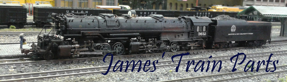
To start with I finally got round to repainting and weathering up my Model Power 4-4-0 as Yosemite Valley Railroad no 22, well Steve at Model Railway Solutions did, as he is much better at weathering than me!

yv-no22-with-log-train

The log cars are unique to the Yosemite Valley Railway and were used on their 88% incline to bring huge logs down from the mountain.  These cars are 3D printed and you can find them and more about them here.

No 22 still has some paint on the wheels to clean off but she did okay hauling a short train around the layout as you can see in the video below, which, if you click on the link will take you to Videscape where I’m now housing all my videos.

The Union Pacific had a big presence this weekend and as usual they also had the biggest engines.  Below is a video of UP Bigboy No 4006 with an empty coal train drifting through town.

UP Bigboy with a coal train through Solent Summit

Later in the day a rather grubby-looking No 4006 was seen hauling a boxcar train through Solent Summit.  These freight cars were also weathered by MRS and you can read about them here.

Not to be outdone the UP diesel department sent through a long freight headed by five EMD locos.  A GP35 upfront followed by a GP7, two GP20 and a massive DD35.  The DD35 is also 3D printed and you can find out about it here and by searching this site for DD35.

But when it comes down to sheer length of trains BNSF had it topped with a very long coal drag headed by a leased SD90MAC, two AC440CWs and tailed by two more.

This sort of heavy traffic plays havoc with the track and BNSF had a GP39M out on maintenance of way duty.

BNSF GP39M with maintenance of way train pulling into Solent Summit

A visitor from just over the border was a Canadian Pacific RS3 with a short propane train.

CP RS3 with propane tankers

We also had a visitor from the other border.  N de M or (Ferrocarriles Nacionales de México) México’s state-owned railway’s Baldwin Centipede made an appearance with a train of Harriman coaches.

N de M Baldwin Centipede with Cross Country Passenger at Solent Summit

Southern Pacific got a look in with a gleaming set of A-B-A Alco PA’s hauling the Morning Daylight.

SP Alco PAs with Daylight Leaving Solent Summit

The UP was still thundering up and down the line with long freight trains but this time with a change of power.  This train is headed by an A-B-A set of Alco C-855s.

UP C-855 Set with a freight train through Solent Summit

The C-855s are 3D printed shells on modified Con-Cor U50/Turbine chassis and you can find out more about them here and by searching for C-855 on this site.

UP C-855 Set with a freight train at Solent Summit

Santa Fe was also spotted rumbling through town with a train of brand new Cat excavator equipment.  The three SD40-2 have all been weathered by MRS; the lead loco, painted in the proposed colors for the failed merger between Southern Pacific and Santa Fe, could do with a good clean.

SF EMD SD40-2s with Cat train Leaving Solent Summit

Amtrak passed by with its combined Super Chief and El Capitan.  Clearly it has not been long since Amtrak took over as some of the rolling stock is still in the former Santa Fe colors.

Amtrak F7 with a combined Super Chief and El Capitan

Burlington Northern had a few trains working the line.  The first was an SD40-2 with a local freight.  This locomotive was the only one to be painted with the tiger stripe front.

BN other train, also hauled by SD40-2s was a loaded coal destined for the power station.

BN SD40-2s with a loaded coal train through Solent Summit

Former Norfolk and Western J class 4-8-4 No 611 was also in town this weekend as part of a steam excursion.  It passed through a few times with a mix of heavyweight coaches.

No 611 was later joined by a SP Hudson No 2486 and together they worked the train over the summit.

N&W J Class No 611 & SP Hudson No 2486 with excursion train

Lastly the Northern Pacific passed through with an A-B set of F7 and a very familiar set of weathered boxcars!

NP F7 with freight

And that is just about it for this week. It’s always a good weekend when there’s no issues to fix and you get to simply run trains.

Next week is the NMRA (BR) annual convention and I will be there.  This year it’s taking place at the The Best Western Plus Manor NRC Birmingham Hotel, Meriden.  And as usual I will be there from Friday to Sunday.  This year we are not taking a big layout, just a few modules to form a switching layout.  If you are coming to the convention please come by and say hello.


Adding a Speaker in a Small Place

Almost a year ago I shared my designs for a 3D printed speaker enclosure which could be built up in sections.  This allowed Zimo speakers to be fitted in even more places.  You can read about it here.  Since then I haven’t had the need for them but just recently I did; and in this week’s post I will share it with you.

Rowa, and later MRC, used to make some wonderful large steam locomotives for N Scale, in particular the 2-8-8-2 Y6b.  When Rivarossi and Con-Cor took over the production they added the 2-8-8-0 EL5 to the lineup.  The EL5 came with a large Vanderbilt tender and it’s one of these I recently added a sound decoder too.

As the shell of this locomotive is full of motor and metal chassis the tender is the obvious place for the decoder and speaker to go.  However, the Con-Cor Vanderbilt tender is a one-piece molding and the body doesn’t separate from the chassis.  To gain access to the inside the back plate has to be removed.  This isthe section between the tender and the locomotive cab just under the coal load.  It’s glued in place but with a gentle bit of pressure it will pop off.  The two metal weights inside the tender will now slide out, giving you full access to the inside.

For this DCC install I am using a Digitrax sound decoder with a Zimo speaker, a LS8x12. This speaker gives much better sound than the standard speaker the decoder comes with.

speaker-fitting-1

As you can see the speaker comes with a sound box.  This is an injection-molded box with a recessed lip around the top which the speaker fits into.  However the box is fairly deep.  My intention is to fix the decoder and speaker to the upper metal weight and slide it all into the tender, but the speaker will not pass under the coal load.

speaker-fitting-2

speaker-fitting-3

To solve this I’ve used two of my 3D printed speaker enclosure sections to form a smaller speaker box. Three sections will make the enclosure the same height as the original.

speaker-fitting-4

The two parts have been glued together with a spot of superglue.  Before fixing to the metal weight I did a test to see if it fitted.

speaker-fitting-5 speaker-fitting-6

The back of the tender is slightly higher than the space under the coal load so although the speaker just scrapes through it will be just fine once in the right place.  I again used superglue to fix the sections to the weight.  The speaker has a sticky foam fitting which holds it into the new enclosure.  The decoder was also fixed to the weight as well as the capacitor, you can see it between the speaker and decoder.

speaker-fitting-7

This whole assembly then slides into the tender and is prevented from moving by the grooves which hold the weight in place.  The last thing to do is connect up the wires.  For this particular locomotive I cut off the plug and hard-wired it in.  Only four wires need to go to the locomotive, so it made sense.

Once the decoder was tested and renumbered the locomotive was ready for service.

speaker-fitting-8

Well, almost ready for service.  The decoder was recycled from another locomotive and, although the sounds work perfectly, they are the sounds for an Alco PA diesel!  This can easily be corrected by uploading some new sounds using Digitrax’s SoundLoader software which is something I will show you how to do in a later post.

For now the speaker enclosure sections should be available by next week and I will share those with you and maybe a video of the EL5 working a train in all its glory.

Drawing a Dummy Chassis & Trucks for an N Scale Alco C-855 Part 1

As you may have noticed from last week’s post I am getting back into the drawing and I’m trying to wrap up some of the outstanding projects. This week I’ve been working on the dummy chassis and trucks for my N Scale Alco C-855.

This also has the advantage of providing all the parts to make a dummy chassis and trucks for Con-Cor’s U50 and 4500 Gas Turbine locomotive shells. I’m sure there are a few spares knocking about now several have been converted into C-855s.

As with all the dummy chassis kits it’s the trucks that take the time.  This is because this is where all the detail is.  The C-855s, U50s and Turbines all had the same truck designs, in fact the same trucks were recycled through the engines.  The original 4500 Gas Turbines were built under the Alco-GE (General Electric) partnership. Alco went on to build the C-855 and GE the U50. The wheel arrangement is specified as B+B+B+B. This means there are four two-axle trucks with all the axles powered. The first and second trucks are linked with span bolsters, as are the third and fourth. In the image below of a Con-Cor 4500 Gas Turbine, with one of my battery box kits, you can see the truck arrangement.

Gas Turbine Batter Box - Clean 1

The first and fourth truck on the model are the only powered trucks and are connected via a gear tower up into the chassis. The second and third trucks are connected to the first and fourth via a span bolster or draw bar and clip into the battery box.

To draw the truck I normally start with a rough image scaled to the correct size, then using actual dimensions I draw the side frames in 3D.

alco-c-855-dummy-truck-1

Then I assemble the frames to form the truck, ensuring they are correctly spaced for the wheel sets.  Depending on how the truck will be connected to the chassis will depend on the truck construction.  These have a central bolster pin.

alco-c-855-dummy-truck-2

The truck isn’t actually finished yet. I still need to add the span bolster section to join the two trucks together and, as you can see, this will be one of the first or fourth trucks because of the bolster pin.

One of the challenges I have with this design is weight. As the first and fourth truck will be carrying the weight of the loco they will stay on the track but the second and third won’t be carrying weight.  3D printed parts are very light, even with metal wheels, so this will make the trucks bounce about. To solve this I will be looking at a 3D printed stainless steel insert, as with the original Con-Cor truck. This will ensure the truck stays on the track and will help them track around corners.

The chassis is an easier issue. As you can see below it is a fairly simple design.  Because of the size I am planning on printing this in the WS&F material simply to reduce the cost as I did with the EMD DD40AX dummy chassis.

alco-c-855-dummy-chassis-2

As I’ve already drawn the Con-Cor chassis in order to work out the extension parts and correct fittings for the shell, all I had to do was copy the shape. In the image below you can see my model of the C-855 powered chassis next to the dummy.  I have left the same mounting points on the fuel tank allowing the shell to clip directly on and there will be ample room inside to add some weight.  Again this is important as the chassis and shell on their own will be very light.

alco-c-855-dummy-chassis-1

Interestingly these three locomotives differ from regular locomotives in that the couplings and pilots are part of the truck and not the body. Normally a diesel locomotive’s strength is its chassis and the couplings are attached to the end of it. The load of the train is transferred through the chassis and the trucks provide the thrust up through the bolster pins. Most early models of locomotives positioned the couplers on the trucks to make them navigate the un-prototypically tight curves on model railroads. However the locomotives with span bolsters do have the couplings on the trucks and the load of the train is transfered through the trucks. The chassis simply rides in the trucks and provides weight for traction. This means I also have to draw the couplings and pilots on the first and fourth truck.

To make the U50 and Turbine dummy chassis it will simply be a matter of shortening the C-855 chassis and changing the centre section to accept a fuel tank or battery box. Once I have solved the span bolster section and drawn the couplings and pilots I will share the next step with you.

Drawing a Dummy Chassis & Trucks for an N Scale EMD SD50

As promised in last week’s post this week I have another design for a 3D printed product to share with you. This one has been knocking around my drawing board, or laptop, since last year so it’s time I got it finished.

So far I have tried to supply a dummy chassis and trucks for the spare locomotive shells left over from donor locos.  For example, I have made a dummy chassis kit available for the Bachmann DDA40X and the Atlas C-628/630.  These locos are donors for my EMD DD35, Baldwin DT6-6-2000 & Baldwin RT-624.  A dummy kit for the Con-Cor U50/Turbine is on its way.

I have also been asked to supply dummy locomotive chassis kits for other shells.  I have several on their way but the first is for an Atlas’ SD50, in particular this Norfolk Southern one.

ns-emd-sd50-dummy-chassis-1

Drawing the actual chassis part is fairly simple, as it will mostly be hidden, so there is very little detail to worry about and I can stretch the one used for the Atlas C-628/630.  The biggest challenge, apart from getting the size right, is to reduce the amount of material used so it’s cheap to print but still strong.  The actual chassis, shown below, is designed to clip into the shell using the same mounting points found on the metal power chassis.  These are on the four upstands. My first design for this system had a solid bar across the top of the upstands,, however this made them too inflexible and it was very hard to get the shell off the chassis.

emd-sd50-dummy-chassis-2

Also any parts that normally protrude into the original chassis have to be accounted for with notches and cut outs.  These are often used as locating lugs designed to get the shell in exactly the right place, which also helps me.

The fuel tank on these Atlas models is a separate injection molded part so the chassis has been designed to receive the tank using the same fixings. Luckily this is simply a longer version of the fixing for the C-628/630 fuel tank so again I can stretch my existing design.

The trucks are the more difficult part because these are on show and there’s normally a lot of detail here.  EMD built their SD50s with two different types of trucks.  The HT-C trucks, which can be identified by the hydraulic shock on the side of the middle axle of each truck, or the earlier Flexicoil trucks.  Only Conrail opted for the Flexicoil trucks so as this model is a Norfolk Southern I have modeled the HT-C style.  Once all the complicated visual parts were complete I had to design a new center section which missed the wheels and held the bolster pin in the right place. The bolster pin is shown below but will be a separate part.

emd-sd50-dummy-chassis-3

As with my previous trucks I have spaced the truck frames to receive 3 Fox Vally 36″ metal wheel sets (FVM3611).  And I have made the same provision for electrical pick-up if required.

emd-sd50-dummy-chassis-4

The axle wipers only make contact with the two outer wheel sets but this is enough to power the original circuit board or a pair of LEDs.  Below is a photo of an actual C-628 dummy truck fitted with the power pickups.  Each truck only picks up power from one rail.

IMAG0603

To use the original lighting board the same clips I used for the C-628/630 can be used as you can below.

Alco C-628 Dummy Chassis Render 12

This fastens around the circuit board and clip into the top of the chassis over the fuel tank void.

emd-sd50-dummy-chassis-5

I have a few more checks to make and then these parts will be ordered for a test print.  When they arrive I will share the results with you before making then available through my shop.

Testing A DCC Auto Reverser and Reversing Section

Just like last week’s post, this week’s is a how-to regarding DCC electronics.  In particular it’s about DCC auto reversers, and how to quickly test they are working.

Why test them?  Well if you have one installed and the system isn’t working it’s a good idea to test the auto reverser away from the layout as it may not be the part at fault. In that case changing it won’t help.

Before I show you how I test them, I will explain how an auto reverser works, and why we need them as I often get asked this.

Imagine you have a straight railway and at one end you have a single point/turnout.  The first track coming out of the point leads to the other via a loop or balloon as in the image below.

loop-track

This allows you to turn a train around but it also creates a problem in that the rails will short each other out.  If you look at the image again you see that the upper rail in the straight section runs around the loop and connects to the lower rail.  This is called a dead short.

To stop this, both rails need to be isolated in two places and in this situation it makes sense to do it just after the point, as shown below.

loop-track-2

The power to the loop can then be supplied separately allowing the polarity to be switched.  This allows a train to run into the loop and stop.  Then a switch is thrown reversing the polarity of the loop power.  The point/turnout is changed and the train can then proceed back onto the line facing the other way without shorting.

But what if the switch was set the wrong way upon entering the loop?  The train will short.  The same applies if you forget to stop the train; it will short when it tries to leave the loop.

This is where the auto reverser comes in.  This device automatically reverses the polarity of the track it’s supplying when it detects a short. Normally when a DCC command station detects a short it shuts the power off so nothing gets damaged.  (Shorting electrical circuits cause lots of heat which is not a good combination with model trains!)  However, the auto reverser detects the shorts and changes the polarity faster than the command station can react, therefore avoiding a shutdown.  This allows a DCC train to run around the loop, assuming the point/turnout is changed, and back out onto the line without stopping or stuttering.

Wiring in an auto reverser is fairly simple, but sometimes you may need to test it to see if it’s working without connecting it up to the layout.  Below is a typical auto reverser.

dcc-auto-reverser-1

Normally they have an input side and a switched output side.  For this one the input is the two red wires.  For the test I have simply used a section of track which is connected to my DCC command station at my work bench.  I quickly soldered the two red wires to the rails, it doesn’t matter which wire goes to which rail.

dcc-auto-reverser-2

Then starting with one of the yellow wires, I touch it to one of the rails.  At the heart of the auto reverser is a relay and you can normally hear it trigger when one of the wires touches a rail of the opposite polarity.  At this stage if the command station beeps or shuts down due to a short, the auto reverser is faulty.  Assuming the command station did not shut down, do the same with the other yellow wire.  Then do both together, but always on different rails as the yellow wires should not touch each other. If that works well then the auto reverser is working properly and is ready to be installed into your layout.

If you wanted to test your auto reverser because it wasn’t working when installed, but it passes the test above, then here are some other things to check.

Are both rails in your reversing section isolated from the rest of the layout? This may cause the loop to work in one direction but not the other.

Is the auto reverser installed the right way round?  The DCC supply needs to be connected to the input side.

Is the reversing section too short?  It needs to be longer than your longest train otherwise the front will try and trigger the auto reverser and the rear will try and put it back.

Is the section you are reversing drawing too much current?  For example: is the section you are reversing a whole staging yard with lots of locomotives in?  Most auto reversers are only designed for about 1 amp and several sound locos could be drawing a lot more.

Is the auto reverser close to the section you are reversing?  The further away it is the longer the wires and the higher the chance of resistance in the wire affecting the short detection circuitry.

Are the DCC wires and track feed wires bunched together?  Having the positive and negative wires directly next to each other can cause problems with the DCC signal due to inductance.  This is the magnetic field generated by each wire affecting its neighbour.

Hopefully this will help in diagnosing any problems you may be having with your auto reversing sections.

Next week I plan to share with you my designs for another 3D printed project, this one should be the first of several I have on the drawing board.

Identifying Your DCC Decoder

This week’s post is a ‘how-to’ about DCC decoders and identifying which ones you have.

As DCC (Digital Command Control) is becoming evermore popular, second-hand locomotives already fitted with DCC decoders are becoming more frequent on websites such as eBay.  It’s easy to grab a bargain but what have you actually bought?  Normally they are just listed as DCC-fitted, leaving it fairly ambiguous as to what’s inside.  Sometimes you can remove your locomotive shell and then see the make and model on the decoder.  But if it was a tricky or custom install it may not be that simple to see.

So why does it matter what the decoder is?  Just about all DCC decoders have the same basic functions, such as motor control and lights, but some are far more advanced than others and have hidden talents.  That being said the one primary thing people change is the address of the decoder, normally to match the number on the locomotive: most DCC systems have that ability no matter what the make or model of the decoder. But if you want to alter any other functions or features which the decoder may have, you will need to know what decoder you’ve got.

This can be done fairly simply by reading the value of CV8 from your decoder.  Now that isn’t as daunting as it sounds and I’ll explain how to read your decoder in a moment.  CV stands for Configuration Variable and it’s these which allow decoders to be set up how you want them.  Different CVs are allocated for different things, for example, CV3 is for Acceleration Rate or Acceleration Momentum.  The higher the value stored in this CV the slower the locomotive will accelerate.  But how do you know which CV is for what?  Well the NMRA (National Model Railroad Association) foresaw this could be a problem and have developed a set of standards for manufactures to follow.  You will notice on all reparable DCC products it will say ‘NMRA compatible’.  This means that all the systems will work with each other so you can use different make decoders and locomotives all on the same layout.

All these CVs can be read using most DCC command stations. This normally involves placing your locomotive on your programming track and selecting the CV Read function.  Depending on which DCC command system you have will depend on how this is done so you will need to look at your instruction manual.  It will ask you which CV you want to read and by selecting 8 it will return a three digit number.  This number will be the unique manufacturer number of your chip.

Again the NMRA control this. They have a list, which can be found here, which has all the manufactures of NMRA complaint DCC products listed by name and by identification number.

So for example if the number was 101 then you have a Bachmann Trains decoder.

Manufactures tend to keep the features and functions the same across their product ranges, so downloading a manual from the manufacture’s website should give you the information you need to set up your decoder.

But what if the decoder in your locomotive is an older model? And companies usually make more than one type of decoder.  To help with this the NMRA have allowed CV7 to be used as a version number by the manufacturers.

So, for example, if your decoder has a CV8 = 129 and CV7 = 49 then you have a Digitrax decoder from the ‘Series 3 with FX3’ family.  There are lots of different decoders in this family but the controls are the same so any instruction manual for a ‘Series 3 with FX3’ will give you what you need.

The NMRA do not list the contents of CV7, as this is down to the manufactures, which can make it a bit tricky to find the information.  But once you know the manufacturer, from CV8, you could email their help desk with the CV7 number and they will be able to help.

Checking the decoder type in your second-hand locos is a good idea because you may be missing out on some great features you never knew you had.