Drawing a Dummy Chassis & Trucks for an N Scale EMD SD50 Part 2

In this week’s post I’ve got some follow-up pictures for my 3D printed N Scale SD50 dummy chassis.  Back in November 2016 I shared with you my designs for this project and you can read that post here.  Since then I’ve ordered the chassis and trucks as a test print, which came out very well, as you can see below.

emd-sd50-dummy-chassis-6

The trucks fitted well and the chassis tracked well along the rails.

emd-sd50-dummy-chassis-7

However, in my eagerness to test the parts I’d forgotten that the fuel tank on Atlas’ SD50 is not the same as their C-628; which I was using as a template model.  Consequently the SD50 fuel tank was much wider and had no way of fixing to the new chassis, as you can see below.

emd-sd50-dummy-chassis-8

This was easily rectified by widening the chassis and creating the required fixing points, as you can see in the computer model below.

emd-sd50-dummy-chassis-mk2-1

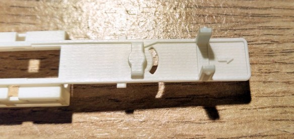
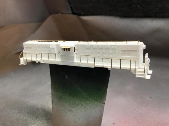
Although this made the chassis much wider I was able to remove the unnecessary material by adding the holes and slots in the sides and base. This keeps the cost roughly the same as before; Shapeways charge by volume of material for their 3D printing service. The chassis section was then 3D printed and now it looks like this:

emd-sd50-dummy-chassis-mk2-2

Compared to the old chassis, as shown below, you can see the significant change which needed to be made.

emd-sd50-dummy-chassis-mk2-3

I also made some other alterations to the chassis.  I added a direction indicator to one end to mark the front; this made sense as the chassis was very similar at each end which meant I kept putting it in backwards!
emd-sd50-dummy-chassis-mk2-4

Also working with the original design I discovered it had a few weak spots which I was able to strengthen by adding stiffeners or simply thickening the material at that point.

emd-sd50-dummy-chassis-mk2-5

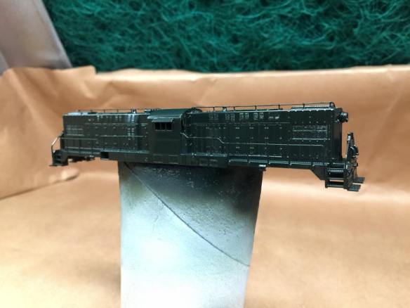
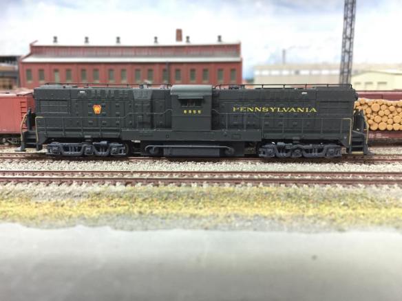
The new chassis and trucks fitted perfectly into the locomotive shell and, although they still needed to be painted and weighted, the dummy loco ran perfectly round the layout with a powered C-630.

emd-sd50-dummy-chassis-mk2-6

The coupling height is spot on but the fuel tank does seem to be very close to the railhead which could cause an issue when the loco crosses a transition to an incline.  However this is easily fixed by gluing the tank to the chassis.  The tolerance in the tank fixing allows it to drop, but when glued it will sit a bit higher.  In the 3D computer model I have lifted the tank fixing up a fraction to avoid this.

emd-sd50-dummy-chassis-mk2-7

I still want to do a few more tests, add some weight to the chassis and paint it to make sure everything is correct before I release the model in my shop but that won’t take long. These trucks have been used on many locomotives so I’ll also be releasing them with different length chassis to fit different shells.  If you have a specific locomotive which you need a dummy chassis for, let me know and I can do that one first.

On another note, this wasn’t the only dummy chassis in my delivery from Shapeways.

alco-c855-dummy-chassis-test-print

This is the considerably larger dummy chassis for an Alco C-855 and I’ll be sharing this with you in a later post once I’ve had a chance to test it out properly, but so far it’s looking very good.

A Way to Paint FUD & FXD 3D Printed Parts

I regularly get asked how to paint the Shapeways 3D printed Frosted Ultra Detail and Frosted Extreme Detail materials.  There are several methods that work but I thought in this post I’d share with you the method used by one of my fellow modellers, Chris Broughton.

Chris produces fantastic models, such as his Baldwin RT-624 as shown below.

RT-624 Button

This model has been made from one of my kits 3D printed at Shapeways in FXD. The kit arrives as shown below, except for the handrails which are fixed inside the shell for protection.

Baldwin RT-624 Kit

Chris also used my etched brass Addition to complete the model.

Baldwin RT-624 Additions Render

From here I will let Chris explain his method for painting his models;

“First, I soak the parts in Bestine to removed the waxy coating from the parts. I’ll leave them in for 2-3 days, since the Bestine doesn’t harm the parts. When the parts come out of the soak, I’ll rinse them in water and lightly brush them with a toothbrush.

PPR RT-624 (Chris Broughton) 1

Once they’re dry, I’ll lightly sand any areas that have a coarse texture from printing. In areas where there’s detail, I’ll using small sanding sticks and try to work around the details.

PPR RT-624 (Chris Broughton) 2

I use Tamiya Fine Surface Primer to prime the parts. If more sanding is necessary, I’ll sand and recoat with the primer.

PPR RT-624 (Chris Broughton) 3

As for paint, I’ve been using TruColor paint more recently. I’m used to using Floquil, so I’ve had to adapt since they’re no longer around.

PPR RT-624 (Chris Broughton) 4

I’ve been pretty happy with TruColor, but I get the best results over a primed surface, and it has to be thinned quite a bit for airbrushing (to the consistency of water). I just use 100% acetone fingernail polish remover for thinning and cleaning. The paint goes on glossy, which is great for applying decals, then spray with Testors Dullcote from a spray can to seal the decals and weathering, and give it a matte finish.”

PPR RT-624 (Chris Broughton) 5

Chris’ finished locomotive looks fantastic which just goes to show how well his method works.

PRR RT-624 8355(Chris Broughton) 3PRR RT-624 8355(Chris Broughton) 2

Many thanks to Chris for sharing his painting method and for the excellent photos.

Last week I had promised to share some new products with you and I will be shortly, I’m just making a few last minute adjustments.  As for this coming weekend I’m going to the NMRA (BR) Benson Winter Meet and hopefully I’ll have some photos and videos to share with you from the show.

A New Tender Draw Bar for a Marklin 4-6-2 – Part 2

Happy New Year and welcome to 2017, and as promised in last week’s post I have a new product to share with you this week.  Back in November of 2016 I posted about a replacement tender draw bar design for a Marklin 4-6-2, you can read the post here.

The locomotive, as pictured below, is tender powered and the link from the engine to the tender is sprung.  This adds a visual softness to the acceleration and deceleration of the engine by helping to disguise any sudden movements when the locomotive starts and stops.

marklin-4-6-2-tender-drawbar-1

The original draw bar was badly damaged and so attempting to glue it together wasn’t very practical.

marklin-4-6-2-tender-drawbar-4

A new draw bar was drawn up and 3D printed in Shapeways Frosted Ultra Detail material.

marklin-4-6-2-tender-drawbar-7

The picture below shows the original springs fitted nicely into the new part.  The raised strip on the left of the part is to stop the spring moving too far when the draw bar is under compression.  The same detail’s on the right but it’s on the underside.

marklin-4-6-2-tender-drawbar-8

Test fitting the part went well, as you can see below.  The system fits by locating the loop in the spring around the peg in the locomotive; there is a bolt in the tender which act in the same way.  As the powered tender moves forward the springs compress untill the force matches the strength of the sprung steel.  Then the engine starts to move.

marklin-4-6-2-tender-drawbar-9

With the loco body fitted there’s a nice close fit between the tender and engine, possibly a little better than the original draw bar as the new one is ever-so-slightly shorter.  Also, because of the spring system, as the locomotive navigates a corner the gap opens up preventing the tender and engine from binding or locking up.

marklin-4-6-2-tender-drawbar-10

The draw bar also pivots at both ends.  The bolt at the tender end is visible near the front of the tender.  The other end pivots under the front of the cab.

marklin-4-6-2-tender-drawbar-11

The last thing to do was remove the new draw bar and paint it black.  Once it had dried and been refitted the locomotive was ready for use.

marklin-4-6-2-tender-drawbar-12

The replacement Marklin 4-6-2 tender draw bar is available from Shapeways here.

Next week’s post will be about another new 3D printed part and I look forward to sharing it with you then.

End of Year Sale

As promised, this week’s post will be nice and quick as today is a holiday, ‘Boxing Day’, here in the UK.

Thanks to Shapeways, who are rounding off the year with an ‘end of year sale’, I’m able to offer sale prices on some of my printed products. They are offering 20% off all Frosted Ultra Detail, Frosted Extreme Detail, and all Strong & Flexible Plastics through January 1st with code FAREWELL2016. You can use the links in the blog or shop on Shapeways site direct, just enter the code at the checkout.

Next week’s post will be the first for 2017 and I’ll be sharing with you the first of many new products.

For now that just leaves me to thank you for your continued support through this year and for 2017 I’d like to wish you all a very Happy New Year!

Replacing the Motor in A Con-Cor Turbine/U50/C-855 Chassis – Additional

Following on from last week’s post about replacing the motor in a Con-Cor Turbine/U50/C-855 Chassis, which you can find here, I have a few updates to share with you.

This chassis has been around since 1973 and has undergone very little change.  However there have been a few, and the more I work with them the more I find.  One of my fellow modelers, Mr Mike Musick, who wrote the guest article about changing the wheels in these chassis, has discovered that the most recent version released under the Rail Baron label has a different motor cradle and the new Kato/Atlas motor will not fit.  You can find Mike’s guest post about the wheel sets here.

The problem with the cradle is solvable by removing the part which clashes with the motor.  Mike says ‘This plastic is hard and not trivial to work with, a Dremel with a small burr bit is about the only way to remove enough material.’  Below is Mike’s photo of a modified cradle.

con-cor-u50-motor-nest

Mike also goes on to say ‘When removing the old motor, be sure to note the location of the “white stripe” on one side of one magnet. This indicates motor polarity, and the new motor should be oriented with the white stripe in the same relative position. This is especially important if it is not going to be modified for DCC;as with DCC if you get it backwards you simply swap the orange and gray wires.

The original motor in mine came with a 0.010″ shim in the motor cradle. So I swapped it out for an 0.020″ shim, which turned out to not be enough, it should be a total of 0.030″.’

The shim raises the motor as discussed in last week’s post, however too much will cause the gears to bind.

With the C-855 extended chassis Mike has also experimented with not gluing the cup gear extenders, shown below, into the cup gears.  This ‘in Mike’s words’ ‘lets the adapter cup gears “float”, which turns them into sort of a constant-velocity joint and may also influence the noise by reducing gear pressure’.

C-855 Chassis Extenders 11

These small changes can greatly affect the running of the locomotive  by improving noise reduction and smoothness of the motor.

Bob’s three C-855s, from last week’s post, have now all had their motors swapped out for Kato Atlas Motors and I was able to catch them this weekend running through Solent Summit station.  I haven’t added any sound to the video so you can hear, or rather not hear, the motors.

Next week’s post will be on Boxing Day here in the UK so it will be nice and short but for now I would like to wish everybody a Merry Christmas.

Replacing the Motor in A Con-Cor Turbine/U50/C-855 Chassis

The Con-Cor Turbine and U50 chassis has been around for many years and has always been a solid runner.  However, by modern standards, the motor in the chassis is rather noisy and draws a lot of current.  In this post I’ll share with you how myself and Bob Norris replaced the motor to improve these issues.

The chassis, as pictured below, has a central motor powering two drive shafts which in turn power the two outer trucks.  The inner pair is unpowered.  The design has been used for the GE U50 model since 1973, which interestingly was first made for Con-Cor by Kato.  This chassis was also used for the GE 4500 Gas Turbine model which was released in 1975.

Con-Cor GE U50-Gas Turbine Chassis

And more recently it’s been used by me for the Alco C-855 as shown below, stretched and fitted with a DCC decoder. You can read more about the stretching of the chassis here or by searching this site for C-855.

C-855 Chassis Build 15

The first three C-855s I made went to Bob Norris and the chassis have been running well but recently we have added sound decoders to them and this started giving us a few problems.  Firstly the motors are fairly noisy and secondly they draw lots of current.  When pulling a heavy train with the sound at full volume the sound decoders have been known to shut off and then start behaving erratically.  Now I know the original three ordered by Union Pacific didn’t last long as they were prone to failure but that wasn’t the aim here!

So after doing some investigating we did a stall test on one of the motors and we discovered that the peak amperage can sometimes go over the maximum for the decoder by a fair amount.  To find out what a stall test is and how to do it please see this post.

Below is a short video of a C-855, running light engine with the sound off so you can hear the motor whining.  The clicking is the Digitrax DCC controller notching up and down.

To solve the issues a new motor was found for the chassis.  Coincidently it is also made by Kato, although a much newer design. The Kato motor 420000 is advertised as a replacement motor for Atlas N Scale.  We found them on eBay though the seller Soo-Much-Stuff.

The motor comes with no gears on the drive shafts which is ideal. Below you can see the new motor on the right and the old on the left.

c-885-new-motor-1

The old motor, as shown below, sat in the middle of the raised area of the chassis and the gears ran inside larger diameter cup gears.

c-885-new-motor-0

The chassis un-screws and separates easily allowing the motor, drive shaft and motor cradle to be removed.

c-885-new-motor-2

The gears on the old motor (top in the photo below) need to be removed and fitted to the new motor.  They are simply press fitted and can be removed by applying pressure behind the gear.  Not too much pressure or you will spend ages looking for the gear on the other side of the layout, don’t ask me how I know this!

c-885-new-motor-3

To fit them to the new motor the process is the same, just the other way around.

c-885-new-motor-4

The gear needs to slide on far enough so the drive shaft is almost at the other side.  Note, this was done for the C-855 extended chassis, the U50 and turbine chassis should be the same but it’s a good idea to check as you go.  If the gear slides on too far it may not make good contact with the cup gear.

c-885-new-motor-5

With the gears fitted the tabs can be bent up ready for soldering wires to.  If you are doing this for a DC locomotive the tabs will need to be in the same positions as the motor you have just taken out.

c-885-new-motor-6

The bottom tab pokes through the motor cradle.

c-885-new-motor-7

Upon test fitting we discovered the motor was sightly smaller than the original which caused it to sit a bit low. To solve this a plastic shim was made to fit in the bottom of the cradle.

c-885-new-motor-8 c-885-new-motor-9

The cradle was then fitted back into the chassis ready for the motor.

c-885-new-motor-10

As you can see below the gears now fit nicely into the cup gears.  If the shim was too thick the cup gears would be lifting and this would cause noise and strain the motor.

c-885-new-motor-11

The wires can now be added to the motor.  There is a channel formed in the C-855 chassis extender on either side so you have a choice on where to run your wire.

c-885-new-motor-13

c-885-new-motor-14

The chassis is now fully reassembled and ready for testing.

c-885-new-motor-15

Below is another short video showing how quietly the new motor runs.

With all three units converted to new motors the performance should be greatly improved and hopefully I will get some video of them running soon to share with you.

Thanks go to Bob for the photos and videos of the motor swap.

The new Shapeways order has now been shipped so next week I will start showing you some of the products I’ve been sharing over the last few weeks.