Fitting DCC to Wrenn OO Locomotives – Horizontal Motors

This week I’m going to share with you a simple way to add DCC (Digital Command Control) to older Wrenn OO locomotives.

Wrenn locomotives date back to the 1960s but don’t be fooled by their age.  They’re very good models and are still widely collected and run.  If you find one in its original box it may even be worth a lot of money, depending on the model inside.

One of their main advantages is they’re all metal, making them very heavy.  This gives them a lot of tractive effort compared to models produced in later years.  The mechanisms are simple but well-built which means most of them are probably still running well.  However these were all designed well before the concept of DCC came along so the motor wasn’t isolated from the chassis.  In fact one of the motor brushes is connected directly to the chassis which makes converting these to DCC a problem.

But to overcome that problem I’ve come up with a simple way to easily make the conversion.  The Wrenn locomotives I’ve come across have one of two types of motor; horizontal and vertical.  This week I’ll cover the horizontal motor which is in the 8F 2-8-0 as pictured bellow, the Castle 4-6-0 and the Rebuilt West Country 4-6-2 which is the locomotive I shall be working on today.

The Rebuilt West Country has the motor and all the wires located under the shell.

With the shell removed you can see a single black wire, which runs from the right hand wheels, connecting into the green wire and going to the right motor terminal.

The left terminal is connected to the chassis by a metal bolt.  Both terminals are linked by a capacitor which acts as a suppressor to prevent interference with televisions etc.  Each terminal also has a spring which keeps pressure on the motor brushes inside the brush holders.

The brush holder on the right is isolated from the chassis and is only connected to the green wire.  The brush holder on the left is the one which gives us the problem.  In the image below I’ve released the spring and the brush has fallen out.  Be carefull not to drop the brush as they are made from carbon, just like a pencil lead, and can easily crack.

The brush holder is made from brass and is fixed directly into the chassis, making a perfect electrical connection.  The brush holder should pull out with a pair of pliers as I have done below.  If not, it will need to be drilled out; if you have to do this dismantle the whole motor first, because you don’t want to damage the inside or get metal filings in the armature.

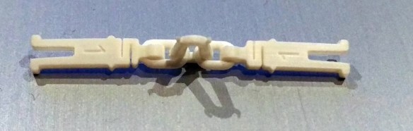
With the brush holder removed it’s a simple matter of replacing it with something which works as an insulator.  And the answer is a 3D printed brush holder.

These have been designed to be a direct replacement.  They are 3D printed in Shapeways’ Frosted Ultra Detail material and should fit into the hole with a push.  It’s important to check first that the brush slides freely inside the holder.  Any print residue inside may cause the brush to stick and this will prevent the locomotive from running.  Any residue can be removed with a drill, the same size as the brush, or a round file.  If the brush holder is a loose fit in the hole simply fix it in place with some superglue.  (Superglue is made from acrylic and so is the Shapeways FUD)

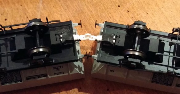
The black wire from the right hand side wheels has been cut and will be joined to the DCC decoder.  The capacitor has also been removed.  Under the left motor terminal is a bolt which also connects this side back to the chassis; this needs to be removed and left out.

At this stage a continuity test using a volt meter is a good idea to ensure the two terminals really are isolated from the chassis and both left and right wheels.  If they are, then the brush can be re-fitted and the spring clipped on to hold it in place.  The wires from the DCC decoder can now be soldered to the motor terminals.

The power feeds can now be connected; one goes to the black wire and the other to the chassis.  I connected the chassis wire to the screw holding on the weight at the front of the loco.

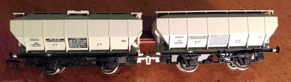
And that’s it, the loco is chipped and ready for testing.

Next week I’ll share with you how to isolate a vertical Wrenn motor and where to get the 3D printed brush mounts from.

A Lot Of ‘Bulleid’ At The Swanage Steam Railway

This weekend I had a nice surprise when passing through Corfe Castle which is small village located in Dorset on the South coast of England.  There was a special event happening at the local heritage steam railway and I thought I would share it with you.

Corfe Castle is famous for having, as its name suggests, a large castle.

Although in ruins it’s a spectacular sight and it’s situated very close to the railway station which is now operated by the Swanage Railway; which is a heritage line.  The station is situated just to the right of the castle behind the town.  In the picture below you can see two plumes of steam, each from a different train sat in the station.  The line runs to Swanage to the right and Norden to the left passing between the castle and the far hills.

The Swanage railway runs steam trains for most of the year but what made this weekend special, and a nice suprise, was the addition of some visiting locomotives.  And they where all Bulleid light pacifics.

As the poster says this year, actually in July, marks the 50th year since the end of steam on the Southern Railway; which was one of the big four.  The others where the LMS (London Midland Scottish), LNER (London North Eastern Railway) & GWR (Great Western Railway).

One of the most influential people for the Southern was Oliver Bulleid. He was the chief mechanical engineer for the Southern Railway between 1937 and the 1948 nationalisation.  As all four companies competed to have the fastest and sleekest looking locomotives Bulleid designed a class of locomotives called the ‘Merchant Navy’ pacifics to pull the most prestigious trains, as pictured below.  Not only where these streamlined but they had lots of modern ideas such as chain driven valve gear and electric lights.

30 locomotives in the class were built between 1941 & 1949 and became know as ‘Spam Cans’ among the loco crews because of the streamlined cladding.  These weighed in at roughly 100 tonnes and although perfect for heavy express work it meant they where unable to travel on some of the regional lines on the Southern network.

This then led to the design of the ‘West Country’ and ‘Battle of Britain’ classes of light pacifics being built between 1945 and 1950.  110 were built in total and were used as express passenger locomotives as well as freight.  All the ‘West Country’ locomotives were named after West Country resorts and worked the west country routes.  The ‘Battle of Britain’ locomotives were named after Royal Air Force (RAF) and other subjects associated with the Battle of Britain and worked the South-east lines.

To mark the 50th anniversary the Swanage Railway brought in four guests to run with their own West Country making a nice set of five:

34052 Lord Dowding – (rebuilt) West Country and originally called ‘Braunton’.

34053 Sir Keith Park – (rebuilt) Battle of Britain.

34070 ManstonBattle of Britain. (Resident at Swanage Railway)

34092 City of Wells – West Country.

34081 92 Squadron – Battle of Britain.

Two of the locomotives are classed as rebuilt and have a very different appearance to the others.  This is because under British Rail (BR) all of the ‘Merchant Navy’ and 60 of the ‘West Country’ and ‘Battle of Britain’ locomotives underwent series of improvements in order to reduce the running costs and improve the performance of the locomotives.  The ‘West Country’ and ‘Battle of Britain’ locomotives went through this between 1957 and 1961 and the changes included the cladding or casing being removed and being replaced with conventional boiler cladding, the boiler pressure being reduced to 250 psi from 280 psi and the chain-driven valve gear being replaced with a modified Walschaerts valve gear which fitted both outside as well as between the frames making access much easier.  The origin chain valve gear was all between the frames inside an oil bath.

Although I didn’t travel on the trains this weekend I was able to catch a few as they passed through Corfe Castle station.

Here is ‘Manston’ arriving with the London to Paris night ferry train.  It’s a bit shorter than it would have been but you get the idea.

The real train ran from London Victoria to Dover.

Leaving Corfe Castle station ‘Manston’ heads for Norden.

Although the Swanage railway is a single track main line Corfe Castle station acts a passing point with two platforms controlled from the signal box.

The platforms are connected with a foot bridge which was great place to watch from.

This is looking north to Norden with the Castle on the left.

And this is looking South to Swanage.  Corfe Castle station has a small good yard at the South end.

I was able to catch ‘Manston’ and ‘City of Wells’ departing in different directions after an exchange.

‘City of Wells’ was on the ‘Golden Arrow’ which was another ferry train from London to Paris but this time it was 1st class all the way.

The train normally would have been made up from Pullman coaches offering every luxury of the age.  And the loco would have been facing forwards.

Lord Dowding (the rebuilt West Country) arrives from Norden.

The rebuilts do look like more traditional steam engines and I think they also look a bit larger however this is an optical illusion as they are basically the same.

‘Sir Keith Park’ (the rebuilt ‘Battle of Britain’) sits ahead of ‘92 Squadron’ awaiting the signal to depart Corfe Castle station.

Double heading was common on some of the steeper routes and is always great to see although for five coaches I don’t think these two have much to worry about.

The scenery in the area is wonderful; and can see why they built the castle here all those years ago; a good rail connection for one!

I leave you with ‘Manston’ running North in the afternoon sun.

OO Gauge Fixed Link Couplings – Part 2

Two weeks ago I started telling you about my OO Gauge Fixed Link Couplings, you can find the post here. In this week’s post I’m going to share with you the design and different types I’ll be making available and why.

As the name suggests these are fixed link couplings and can’t be uncoupled.  They’re designed to allow strings of rolling stock to be coupled permanently in sets with the correct-looking couplings.  This is ideal for exhibition layouts or block trains which don’t need to be shunted.

The two basic styles, as pictured below, are Instanter, shown in green and 3 link, shown in red.

The actual style of Instanter or 3 link is purely cosmetic as this simply forms a rigid fixed link between the NEM connection.  Why did I do this instead of leaving the chain links loose?  Well, if the links were loose it would alow the coupling to close up when a locomotive is pushing the rolling stock, but this would mean the loco will be pushing on the buffers. Unlike the real thing this doesn’t work very well on most ready-to-run OO rolling stock and tends to lead to derailment.  Having the chains fused turns the coupling into a drawbar and as it’s centered on the rolling stock it allows long trains to be pushed without any issues. To fuse the chain links I have drawn a bulge making them a bit fatter where the links meet; this causes them to overlap and become one solid piece.

As I said above, making the connection into a solid drawbar gives the advantage of allowing the train to be pushed but what about going around curves?  The NEM sockets do allow a bit of sideways movement but depending on which manufacturer will depend on how much. So I have designed in a flexible section at each end which allows for some more movement.  This can be seen on the Instanter connector below.

As the coupling bends either to the left or right one of the gaps will open slightly.  When the train is being pushed the gaps close equally keeping the force straight.

Below I have two brand new OO Bachmann covered hopper wagons linked with the coupling above.

As the trucks are twisted to the max, where the buffers touch, the NEM socket swivels as well as the flexible section in the coupling.

The different types, apart from Instanter and 3 link, refer to two variations in the NEM sockets.  The first is length, or rather the distance the NEM socket is set back from the front of the rolling stock.  Although the NEM standards specify the size and position of the socket, not all manufacturers have them in the same place. Length is also governed by the tightest radius curve on your layout.  The tighter the radius the further apart the rolling stock needs to be before the buffers lock and cause a derailment.  With some exhibition layouts which only have big radius curves my shortest couplings can be used.

The second is height, some NEM sockets are lower than others.  To solve this I did an in-depth survey of all the main manufactures and determined that the issue could be overcome with three different shapes, which are all shown below.

The top one is simply a straight coupling.  The second is a cranked coupling and the third is a step-up coupling.  Below you can see the same two Bachmann hopper wagons with a straight Instanter fitted.

The Bachmann NEM socket is low and consequently so is the coupling.  By using a step-up coupling it raises the Instanter.

The cranked coupling is designed to be used when connecting rolling stock from different manufactures.  For instance, below are a Hornby and a Bachmann coal wagons.  The Hornby NEM socket is higher than the Bachmann but using a cranked coupling solves the problem.

You many have also noticed the original plastic molded hook is still on the model above the coupling.  My couplings technically are still lower than the real thing but doing it this way means you don’t have to modify your rolling stock if you don’t want to as the new couplings simply plug-in.  I will also be offering an advanced range which raise the couplings to the corrected height but this will require the plastic molded hook to be cut off.

Next week I’ll share with you the full range of my OO Gauge Fixed Link Couplings as well as a way to judge which ones you need.

UP Coming Exhibitions

This week I had planed on sharing with you the next part of my ‘OO Gauge Fixed Link Couplings’ post.  But time has simply got away from me so this week I will be brief and just let you know that I, and my fellow members of the Gosport American Model Railroad Group, will be at the Bristol Model Railway Exhibition with our N Scale modular layout ‘Solent Summit’.  The exhibition runs from Friday the 28th of April to Sunday the 30th and you can find out all about it here.

Next week I will be back to the ‘OO Gauge Fixed Link Couplings’.

OO Gauge Fixed Link Couplings – Part 1

As promised in last week’s post, this week will be about 3D printed parts.  And these parts are OO Gauge couplings.

Traditionally OO gauge locomotives and rolling stock in the UK have relied on the hook and bar coupling or tension-lock shown below.  These date back to the Hornby Tri-ang era and although they work well they are rather unsightly and are in no way prototypical.

For many years different manufacturers trimmed and improved the design but there was no getting away from that huge hook and bar; otherwise their locomotives and rolling stock would not couple up to everybody elses.  Also there had to be a lot of gap between the couplings to allow trains to navigate very tight curves.  Starter sets and train sets always come with a tight loop of track and all the manufacturers wanted their trains to go around them.

Naturally exhibition layouts didn’t want this type of coupling and the modelers invented all sorts of ways to close couple and accurately represent the real couplings for their era. Many kits are now available but on older models a bit of cutting and drilling is normally required and this can get a bit tedious and expensive.

More recently the majority of manufactures have now standardised their couplings in that they have added a NEM pocket to the underside of their rolling stock.

A NEM pocket or socket, as pictured below, is a standard pocket which complies to NEM 362.  This stipulates the size and position of the socket.  The intention is that all rolling stock has a NEM socket which allows any type of coupler to be simply plugged in and will be at the right height.

Currently just about all OO stock now comes with a tension-lock coupling plunged into a NEM socket.

This now opens up the possibilities of getting correct couplings for your era.

Real modern UK rollings stock use the Bukeye connector which is the same design as the standard US equipment but this didn’t happen untill recently.  Early rolling stock was coupled by a 3 link chain and hook as shown below.

Each end of the wagon has a cast hook and a 3 link chain.  Therefore each end is universal and either chain could be lifted and dropped over the hook.  This simple method worked well but rolling stock snapped back and forth as the train accelerated and braked. The buffers are sprung as to absorb the impact but as the trains got heavier it became more of a problem so the Instanter coupling was invented.

This new coupling, as shown below, is similar to the 3 link but the central link is a special cast iron shape.

The coupling can still be used as a loose fit coupling or can be rotated to make it a close coupled connection.  To do this the wagon brake is applied and the locomotive pushed up which compresses the buffers.  Then the chain can be put over the hook and the center link easily rotated.  When the locomotive releases the pressure the buffers release but not all the way as the chain is now much shorter and pulls tight.  Because of the rounded shapes at the top of the Instanter it cannot rotate and keeps the link short.  Now the rolling stock is close coupled and will not snap back and forth.  In the drawing below you can see the Instanter in its rotated position with the rounded shapes at the top.

The two horns at the bottom of the Instanter are there to aid the shunter when they want to release or connect the coupling.  Once the locomotive has pushed up and compressed the buffers the shunter uses a shunter’s pole, as shown below, to hook the coupling up and over.  The metal ‘pigs tail’ in the pole hooks onto the horns.  This makes the shunter’s job safer as they don’t need to go between the rolling stock to couple up.

Many modelers are switching over to Kedee couplings, one of the American standard couplers, as they now supply a coupling which fits directly into the NEM pocket.

However these can be fairly expensive and what if you model older stock which would have had an Instanter or 3 link coupling?  Well the answer is a 3D printed couplings.

My design for these has evolved over the last few months and have been tested thoroughly.  Now I have a set which works in a variety of situations and in next week’s post I will tell you all about them and share with you some photos and videos of the real thing.

Bournemouth N Trak Convention – 2017

As promised in last week’s post, this week will be about the Bournemouth N Trak Convention which was held here in the UK last weekend.

For those who don’t know what N Trak is all about, have a look at my post covering this convention from 2014 which can be found here.  I gave a description and showed many shots of the N Trak layout, the same one we used this year.

As usual a real mix of rolling stock and locomotives run on the layouts over the three days as all the participants run their new acquisitions and their tried and tested favorites.  For example, below you can see a modern-day UP heritage locomotive and an 1880s 4-4-0 working the yard.

bournemouth-n-trak-2017-1

Yosemite Valley Railroad 4-4-0 No.22 waits for a train as other locomotives go about their duties.

bournemouth-n-trak-2017-6

Later in the day No. 22 moves some freight cars into the lumber mill.

bournemouth-n-trak-2017-2

Although switching the industries is fun the main action on is on the three main lines and we had plenty to see.  Union Pacific had a big presence and not just in quantity.  Below is a video of a weathered Scale Trains 8500 Gas Turbine running through town.

Not to be outdone a brass 8500 GTEL made by Overland Models was also running the rails, again nicely weathered.

In fact we had several of the new Scale Trains 8500 GTELS on the layout. Here’s another one with a long train of ethanol tankers.  Hmm, large turbine exhausts and ethanol tankers, is that a good idea?!

But just as with the real 8500 Turbines, these were replaced and what could be better than the A-B-A set of C-855s from Alco?

But they were short-lived and now we have a pair of EMD SD9043MACs hauling a wind turbine train.

Plenty of other railroads had a good run as well.  Below is a Southern Pacific cab forward.

A pair of Santa Fe GP30s with a fast freight.

A pair of Santa Fe FP40s with the ‘Cat train’ delivering Caterpillar machinery.

And a brass set of Milwaukee Road Erie Builts with Hiawatha stream liner.

Switching carried on in the background as you can see by this Pennsylvania S2.

Again the Black Diamonds came with several modules from their large modular collection; this time it was a large grain facility.

bournemouth-n-trak-2017-4

bournemouth-n-trak-2017-7

bournemouth-n-trak-2017-8

This allowed a lot of switching action while the main line remained busy with trains.

bournemouth-n-trak-2017-3

A motel was situated at one end of the grain facility, ideal lodgings for rail fans.

bournemouth-n-trak-2017-9

As usual the layout was topped and tailed with large looped yards.

bournemouth-n-trak-2017-10

There were several other scenic boards in the setup, such as this rustic farmstead.

bournemouth-n-trak-2017-11  But my favorite section was the twin bridge across the river.
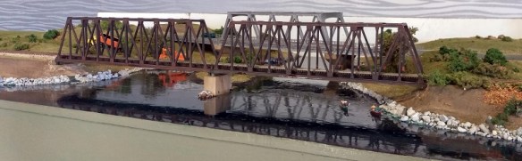
bournemouth-n-trak-2017-5

This also added operational interest to the layout as everything else was a double track main line, except this bridge, so trains had to wait their turn to cross.

bournemouth-n-trak-2017-12

And it was at this bridge where I managed to catch some trains on film.

A Western Pacific stream liner slows and runs across the river.

This Micro-Trains collectors’ set of State cars, locomotives and caboose looked very impressive.

My Southern Pacific overnight train made an appearance powered by an A-B-B-A set of F7s.

A lone Santa Fe FP45 pulls a long freight over the river.

An Arizona Eastern Railway trio of locos trundle over the bridge with a mixed freight.

And finally, do you remember that 1880s 4-4-0 from the beginning of the post?  Well here it is crossing the river with log, freight and passenger car train.

This convention, although small, is always great fun and I would like to thank the members of the N Trak, the Black Dimonds, Neil’s Engaging Trains and the N scale Architect for making the event happen.

Next week I’ll be back to 3D printing and will have some new couplings to share with you.