EMD DD35 With Body Mount Couplers – Part 1

This week I have a modified shell to share with you for my N Scale EMD DD35 project.  The new shell option incorporates body mounted couplers rather than truck mounted.

My DD35 3D printed shell is designed to fit onto a modified Bachmann DDA40X chassis which has truck mounted couplings.  Only the shell and fuel tanks are 3D printed, the trucks and pilots come with the chassis.  You can find the kit here.

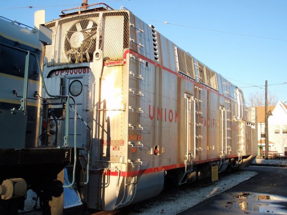
The real DD35, and the DDA40X, has body mounted couplings, or rather chassis mounted, which allow the trucks to rotate freely under the chassis.  I originally decided to leave the truck mounted couplings on the model, simply because of the length of the locomotive.  As it’s so long, body mounted couplers will cause a problem with tight curves.  As the locomotive navigates the tight curve the coupling moves too far away from the center of the tracks and can pull the connected rolling stock off the rails or derail the locomotive. That’s also why Bachmann built the DDA40X model the way they did.

But some layouts have larger radius curves than others and I was asked if I could produce an extra part to allow body mounted couplers to be fitted.  So I did and they looked like this.

These came in the form of a pilot section with a cutout for a body mount coupling which, with a bit of modification, could be fixed to the underside of the shell.  You can read my post about them here and they can be found here.

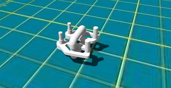
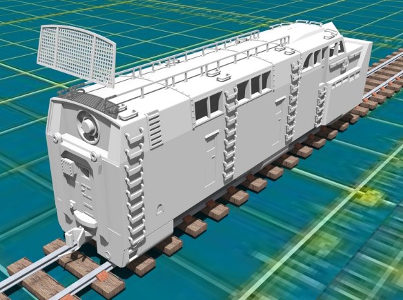
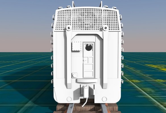
But the ideal situation is to have the pilots 3D printed as part of the shell and that’s what I’ve done as you can see in the renderings below.

The new pilot section has the pocket and screw hole for Micro-Trains body mounted coupling.  The problem comes with fitting the new one piece 3D printed body section onto the chassis which is now too long.  As the pilot sections tuck under the chassis this makes it impossible to simply drop the body down onto it.

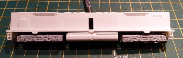
The original modified chassis, as shown below, has the pilots attached to the trucks and the chassis stops roughly where the pilots start.

To make the new shell fit, the first thing to do is remove the existing pilots.  These are held on with two screws which release the coupling and pilot.

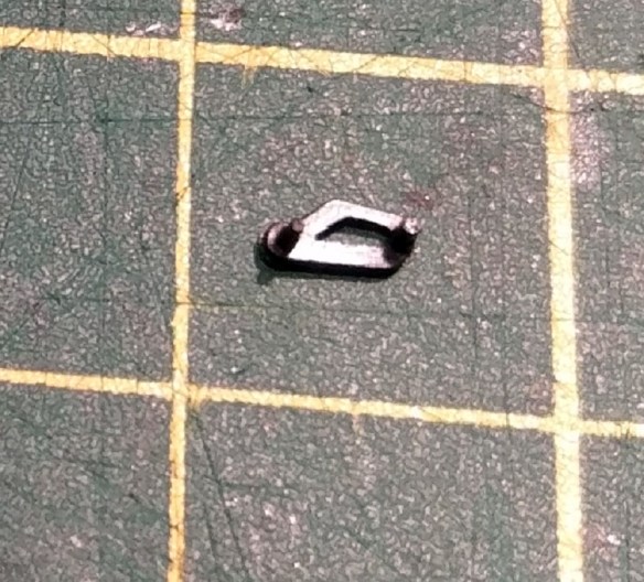
The pilot mount is plastic and projects from the truck frame.

This needs to be cut off and that can be done with pair of side snips.

The chassis also had to be shortened by filing the ends.  From point to point the chassis needs to be 150mm (5.906″) long in order to fit inbetween the new pilots on the 3D printed shell.

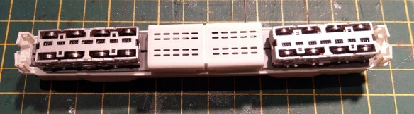
With the chassis reassembled it now looks like this.  I also filed a chamfer on the four corners to ensure the shell was a good fit.

One other modification I made was to file off the four locating bumps on the sides of the chassis.  These normally located the DDA40X shell which has matching holes on the shell.  As the DD35 shell doesn’t have these holes and is held in place by the length of the chassis they are not required.  They will also cause the shell to spread if left in place.

The new shell, which is 3D printed in Shapeways Fine Detail Plastic, fitted onto the chassis and clipped into place, as did the fuel tank.

Once the shell has been painted I will fit the body mount couplers and get some videos of the DD35 traversing curves with its body mounted couplings. I’ll share that with you in another post.

N Gauge Peppercorn A1 Replacement Bell Crank Covers

This week I have another new replacement part to share with you for an N Gauge Bachmann (Graham Farish) Peppercorn A1.

These locomotives, as pictured below (Bachmann stock photo), are fairly new and therefore not a lot goes wrong with them.  They are fantastic runners.

But from time to time parts can come off and get lost, and that’s what happened to this one.  Where the eccentric rod connected to the bell crank Beckman have secured the rod with a plastic molded part with two pegs as shown below.  These parts are opp-handed so they are different for each side.

Drawing the part is fairly simple, as I had one to copy, and I’ve joined both parts together to make them cheaper to print and keep them in pairs.

The new parts, which being transparent are very hard to photograph, came out very well and are almost identical to the original.

On the locomotive below you can see the eccentric rod hanging down.  The two holes under the running board receive the pegs on the bell crank cover.  The hole nearest the front of the loco pins the eccentric rod.  At the end of the rod is a plate with three holes; the middle hole is oversized to allow the plate to rotate in on the pin.

With the original cover fitted, as shown below, you can see how it all fits together.

On the other side the new 3D printed part fits in the same way.

This 3D printed part has one of the pegs ever so slightly, and I mean 0.3mm, too low on the cover.  This causes it to appear to be at an angle.  I’ve corrected this in the model file.

Once painted with a matte acrylic black, the new cover fits right in with the locomotive.

For symmetry I changed the other side for a 3D printed part as well and again it fits right in.

Upon test running, the locomotive is as smooth as when it was new.  A pair of replacement N Gauge Bachmann (Graham Farish) Peppercorn A1 bell crank covers can be found here.

Next week I’ll have another new replacement part to share with you and then it’s back to the projects in hand.

Union Pacific Rotary Snow Plow 900081 – Part 4

To start this week I’d like to apologize for the lack of a post last week.  It had been a busy weekend at work and I simply ran out of time.

But the good news is I’ve made some, albeit small, progress on my UP Rotary Snow Plow project.  If you are new to this project you can start reading about it here.

Most of the body section is now drawn, although there is plenty of detail to add.  The one big space left to do was the rear of the unit.  And as most of the attention is drawn by the large fan at the front, the rear is often overlooked by photographers. This causes a problem for me to get information, and there’s a lot going on back there.  However thanks to Flickr and the photos of Dustin Holmes I have some great resource material to draw from, as you can see below.

Apart from the door, which is not centered on the body, and all of the grab irons and pipes, there are two lifting points which frame the door and the large fan at the top behind the grill.  This 48″ fan is a Dynavane blower, which delivers clean air to the motor, and traction motors which drive the cutting fan on the front.  This is necessary when the snow is falling hard and the air supply gets congested!

In order to model this and make sure the fan could be seen I’ve decided to make the mesh from etched brass. Below you can see the mesh closing off the rear of the body.

Behind the mesh will simply be the fan and a recessed area.  The sides of the body extend into the void as I need to alow space for the grab irons to run into and to give structural integrity to the body.

The actual fan will be printed as part of the body and therefore unable to rotate, but I don’t mind that, after all this is N Scale.

I will look at making the actual mesh as fine as possible so the light can get in and show the fan but from the render below you get the idea.

I’ve also added a coupling pocket for a Micro-Trains 1015 Body Mount coupler.  There will be a screw hole printed into the body to hold it in place.

I’ve also finished the directional cover which forces the snow either to the left or right.  This again will be made from etched brass as I want to be able to move it from side to side.  If I made this as a 3D printed part it would be too bulky and not look very realistic.  There will be a pair of holes on the cover which will clip over two pegs 3D printed onto the side of the exit chute.

Now I really need to get back to the chassis and finish working out how to modify it to fit in.  Once I have done that I’ll have another update for you.

Union Pacific Rotary Snow Plow 900081 – Part 3

In this week’s post, as promised last week, I’m going to share with you a bit more progress on with my UP 900081 Rotary Snow Plow kit.

A major part of a rotary snow plow is the fan at the front and for my kit not only do I want it to be functional but I also want it to look right.  And the UP 900081 has a very complex fan.

The red sections look smaller than the silver parts, however, they are the same.  Each blade has wings which fold out to alter the size of the blade.  All the red ones are folded in.  In the close up photograph below you can see the wings on blade number 6.  Blades 5 and 7 have had the wings removed.  You can also see the circular chute the snow is forced down behind the wings. The chute slopes away from the center of the fan towards the back of the fan chamber.  As the blades cut the snow it’s forced down these chutes and as each chute reaches the top of the rotation the snow is blasted out through the hole on the top of the fan chamber.

It would be very easy to simply make a flat disc and add details to the front but I wanted to replicate this detail as closely as I could, particularly the blades and the circular chutes.  3D printing gives me the ability to make this complex shape and maintain strength at a 1:160 scale.  In brass at this scale it would be a very difficult task.

The fan will be printed in one piece with a shaft at the back.  This will pass through the shell bulk head and be connected to a gear which will be driven by the motor.  The fan will also be a separate part from the main body to allow easy painting of both the fan and the fan chamber.  In the render below you can see the fan located in half of the body shell.

The exit chute is directly above the fan.  Above the exit chute will be the directional cover which will force the snow either to the left or right.  This cover will probably be made from etched brass as a 3D printed part will appear to be too thick. The actual wings on the fan haven’t been drawn yet either but I do intend to add this detail.

Because the fan is modeled fairly closely to the original you will be able to see the end of the circular chutes through the exit chute.  However in order to retain strength the circular chutes don’t go back as far as the original.  As a compromise I have added a cut out detail in the side of the fan which you will see as it rotates.

My next task, once the fan and exit chute is finished, will be to work out a reduction gear system so the motor speed is reduced in order to spin the fan at a slower speed.  And in order to do that I need to complete the power chassis and that’s something I’ll share with you in a later post.

New Axles for A Bachmann HO 4-8-4 Northern

I often get asked to have a look at damaged locomotives and see if there’s anything that can be done to repair them.  And I’m happy to say most of the time there is.  So this week I have another 3D printed part made specifically to repair a locomotive to share with you.

Bachmann make model locomotives in many scales and I normally work in N Scale but this time it’s HO and it’s a lot bigger than N!

This locomotive has a motor in the rear of the boiler which drives the rear axle.  The other wheels, just like the real thing, are driven by the connecting rods on the side.

However this particular model suffers from cracked axles causing an issue with the quartering. But what does that mean?

Well, as each driving wheel picks up power from the rails the axle needs to be electrically isolated to prevent it from shorting and this is done with a plastic axle.  Each metal wheel has a peg at the center which fixes into the plastic axle.  Below you can see the chassis upside-down with the base removed.  Between each driving wheel you can see the plastic axle and between the rear wheel set is an axle with a gear which is driven by the motor.

This all works well untill the plastic becomes weaker with age and the pressure of the wheels turning causes it to crack.  In the photo below you can see the crack line running through the original axle.

When it’s cracked like this the peg on the wheel will not be fixed tightly into the axle and the wheel can move differently to the wheel on the other side of the axle.  And it’s this which causes the quartering issue.  Quartering is a name given to the positioning of each wheel relative to the cylinder and piston.  In the image below you can see all the wheels are connected to the connecting rod at the same point.  Half way around the wheel on the left hand side, or at the 3rd quarter point.  And the piston will be all the way to the front of the cylinder.

At the same time on the other side of the locomotive the wheels are all connected at the top of the wheel or the 1st quarter point.  And the piston will be in the middle of the cylinder.

All steam engines are offset like this, although some are a bit different if they have more cylinders, but it’s this offset which ensures one cylinder can always push on the wheels no matter where the locomotive stops.  If both side rods were in the same position and the locomotive stopped with the cylinders in the middle of a stroke, it would be nearly impossible to get it going again.  So either side of an axle a driving wheel is positioned a quarter of a turn apart.   But if the axle doesn’t grip the wheels then they get out of sync, the side rods get jammed up and the locomotive stops moving.  And that is exactly what has happened to this locomotive.

However, there is a simple solution.  I have drawn a replacement set of axles and 3D printed them in Shapeways Frosted Ultra Detail material which is accurate and hard-wearing, so ideal for this replacement part.

Yes, I know the original had a square section in the middle but out of the three I’ve changed only one of them did and I don’t know why. The other two had round sections and as I could see no reason for it being square I made them all round. If anyone does know why, please get in touch.

And as you can see in the image of the chassis the axles fit well.  The wheels push in with a tight fit and stay at the correct quarter spacing.

I’ll be making these axles available soon in my Shapeways shop so if you also have a Bachmann HO 4-8-4 with spit axles you’ll be able to fix it and keep it running.

Union Pacific Rotary Snow Plow 900081 – Part 2

In this week’s post, as promised last week, I’m going to share with you which chassis I’m planning on using with my UP 900081 Rotary Snow Plow kit.

The reason why I plan on using a commercially available chassis is I want to make it easy to build and have reliable power pickup.  This will make powering the fan on the front much easier.  I can 3D print trucks, add contacts and fit metal wheels but when there’s something already available, which also has a motor and drive shafts, it seems the right way to go.  However the UP 900081, and UP 900082, have two different trucks front and back and the truck spacing doesn’t match anything else so it’s not going to be that easy.

The chassis I’ve chosen as a starting point is made by Kato and can be fitted in to all sorts of things but I think it was designed for Japanese street cars.  The 11-105 is the first of three including 11-106 and 11-107.  All three are the same just with different trucks.

The chassis are fairly cheap and available in lots of places online and in local hobby stores.  Plus they are great runners.

The plastic top is held on by four clips and simply pops off.  Underneath is a motor at one end and a worm gear and truck tower at the other.  There is a drive shaft connecting the two.

This means that only one truck in the chassis is powered by the motor, the other is free running but still picks up power, which is ideal for me.

With the top gear removed from the truck tower the chassis will become free rolling but maintain pickup from all the wheels.  This then allows the fan to be connected to the drive shaft.  This will also take a bit of figuring out as I want to incorporate a reduction gear box which will dramatically reduce the speed of the fan.  Although I intend to convert this to DCC, which will be very easy, simply telling the motor to run really slowly may cause it to stall or seem jerky. Having a gear box will allow the motor to run at a good speed whilst the fan slowly turns.

All that quality pickup will also make it easier to install sound as well, which is an interesting option.

As I said before, there are a few issues with the chassis. Firstly, the truck spacing.  This can be overcome by extending the chassis frame or simply 3D printing a longer one.

Secondly, the trucks themselves are the wrong type, and one doesn’t have enough wheels!  But this too can be overcome and again it will involve some 3D printed parts.  I haven’t decided yet whether to file down the existing side frame and stick on new ones or whether to 3D print a new truck outer section, but as the design develops that will become clear.  At this point you may be asking what is left of the original chassis?  Well, the motor and power pickup, which given the relative cheapness of the chassis is well worth it.

So I have a lot of design and drawing ahead of me on this project and next week hopefully I will have a bit more progress to share with you.