Drawing the Pre-Rebuilt/Ex Gas Turbine UP Water Tenders

Now the model of the current UP excursion train water tenders is all finished in N scale, I turned my attention to the Pre-Rebuilt version.

My original thoughts were that this would be an easy design, as I had already drawn the main components, all that I would need to do is remove the embellishments, adjust the shape and print.  I was very wrong.  Although the two designs were built from the same tender they went through a lot of changes to get from old to new.

Here are two of the tenders in their 1955-2007 configuration.

UP Pre Rebuit Tender(Photo by Richard Wrede)

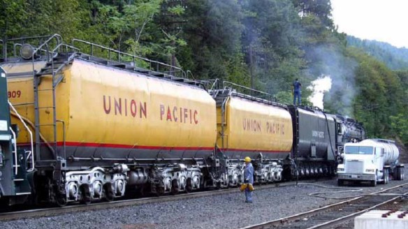
(Photo by Richard Wrede: UP 3985 In Dunsmuir,Ca. taken in 2005)

And here is one in it’s 2007-present configuration, and yes they are the same type of tender.

UP844 April 21st 6

The obvious details that where different from the new 2007-present tender such as the grab rail on the top and the chamfered ends would be fairly easy to do.  The main challenge I encountered was the actual shape if the tender body.  The Pre-Rebuilt body is wider, and longer.  Not because it is bigger inside but because the whole tender was insulated and clad with a second metal skin.  These tenders were ‘hand me downs’ form the large 8500 class Gas Turbines, this cladding covered the heating equipment and insulation which was used to heat the Bunker C fuel oil.  Remembering we are working in N scale at 1:160 I pondered about not changing the body width, that would mean all I had to do was remove the rivet detail from the sides.  But I just could not bring myself to do it so I widened and lengthened the bodies.  This in turn meant both ends had to be remodeled as the radius intersections where the curved areas meet the sides all moved.

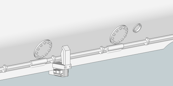
With new body modeled in, I could then start adding the detail.  Service holes on the sides are shown below.

UP Water Tender (Turbine) Survice Holes

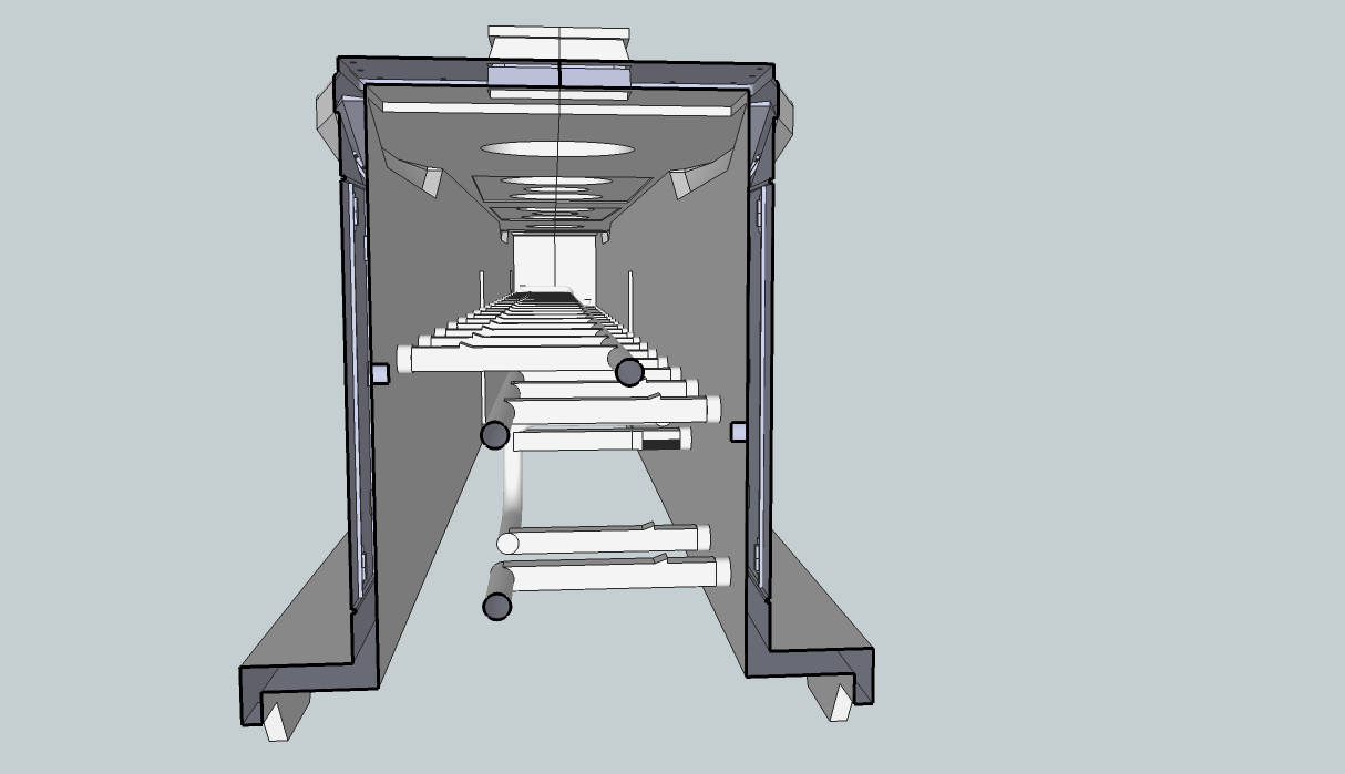
End pipe work and electrical ports.
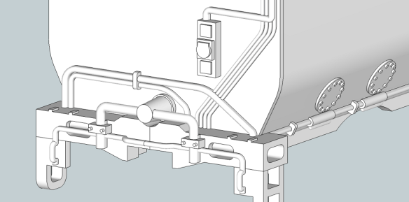
UP Water Tender (Turbine) End Pipework

UP Water Tender (Turbine) End Pipework 2

And side piping.

UP Water Tender (Turbine) Side Pipework

This cars had a lot of piping and from the reference material I could find, it varied from car to car.  The two most common differences I could find, mainly with the pair UP have been using with the heritage fleet, was one had piping running over the top to the service hatch and one did not.  Here is the pipe work going to the hatch.

UP Water Tender (Turbine) Pipework Hatch

Using the reference material I was able to mostly work out where the pipes went, some just seemed to go nowhere.  Putting them in over the curved end was the trickiest part as this surface curves in two directions and the pipes don’t run in a straight line.  The piping on the model is not actually round, to give it strength it is curved on top and squared down to the body, making it into an elevated detail rather than a separate object.  This is almost impossible to see in N scale and gives the look of piping running over the body, plus it makes it strong.

Next came the top area, and this car it is covered with an open grill mesh.  This is very hard to do, not that it can’t be printed but because it would either look way too chunky or be so fragile it is unlikely to survive the cleaning and handling process.  To overcome this, the piping which runs along the side of the body between the grill mesh and the top of the body has been closed off as shown below forming a solid object.

UP Water Tender (Turbine) Solid Top

The grill has then been drawn as a recessed detail which now forms the top of the car.

The end ladders are also different on this tender, plus they had steps made from the same grill mesh.  This made them fairly quick to model, plus this time all four are the same.

UP Water Tender (Turbine) Ladder

As for the grab rails along the top, once again they would either look way too chunky or be too fragile so I have not included them in the print, however we will cover them in a later post.

The final details to add such as the tool box came last.  The trucks and chassis where used from the previous water tender model, although I couldn’t help my self and did some improvements on those too.

And here is the finished 3D model.

UP Water Tender (Turbine) Type 1 & 2

And you can get them here.

So not the quick turnaround I first considered, but I think well worth the extra effort.  The model is sized correctly and I think it will look fantastic.  In a later post I will show how it came out.

Drawing the UP’s auxiliary excursion train water tenders for N Scale

The Union Pacific railroad heritage fleet currently runs two of their preserved steam locomotives on regular excursion trips and, with the very much anticipated Bigboy No. 4014 re-entering service in the next few years, the modelling of the excursion train will become even more popular. With Athearn’s new N scale Challenger and Bigboy locomotives, or even the former Rivarossi models, and the Kato ‘City of Los Angeles’ cars, this can easily be done. The one important thing missing is the extra water tenders now always used for the long trips.

Ever since the switch from steam power to diesel the supply of water along the railroad has all but dried up; often you can see local fire department filling the excursion train locomotives water tanks with their pumping equipment at stops along the way. To combat this UP have created auxiliary water tenders which hold more water than the engine’s own capacity and greatly increases the range of the excursion trips. Currently, my understanding is, the UP has four auxiliary tenders in the heritage fleet.

Here is UP 844 in Oakland, California in 2009, accompanied by one of the auxiliary tenders whilst on an excursion trip stopover.

UP844 April 21st 1 UP844 April 21st 2 UP844 April 21st 3 UP844 April 21st 4 UP844 April 21st 5 UP844 April 21st 6

These tenders started life as regular coal and water tenders for the 800-class steam engines until the engines where decommissioned due to the new diesels. However when the new 8500 class gas turbine locomotives, built by General Electric, started being used by the UP, the need for tenders to hold their bunker C fuel oil was created and the old 800-class tenders where recycled for this purpose. Because the bunker C fuel oil needed to be kept warm so it could be pumped as a fluid, the tenders were fitted with a heating system and a second metal skin for insulation and to cover the system. When the UP retired the 8500 Gas Turbines the tenders remained in storage until the heritage fleet commandeered them for the excursion trains. The heritage fleet used the tenders in this configuration until 2007 when two were rebuilt removing the heating system and the second skin. This increased the water capacity by 3000 gallons to 28,000 gallons. These two tenders were christened UPP 809 Jim Adams and UPP 814 Joe Jordan after two retired steam fitters from the UP repair shop.

I wanted to produce models of both versions of the tenders so I could replicate both periods (pre and post 2007). I decided to start with the newest incarnation and set about producing a 3D computer model.

UP Water Tender10

I used a mixture of images and drawings from the internet and books to get the correct dimensions.  There’s a 8500 gas turbine and tender at the Illinois Railway Museum and they have lots of good pictures, as do Wasatch Railroad Contractors, who did the conversion on water car UPP 814.

UP Water Tender8

Some elements were simply too small to be reproduced in N scale, such as the handrails that run along the top and up the ladders.  I decided that it would be best to add these using brass wire at a later stage.

UP Water Tender9

To make this easier to paint I separated some of the detail parts from the main model body.  The ladders, roof tool boxes, headlights and flag plates are all loose parts, as are the trucks, chassis and bolster pins.  Here are the parts laid out ready for the first test print.

UP Water Tender6

The body has been designed to take Micro-Trains body mount couplers.  The bolster pin that holds the trucks to the chassis has also been positioned off centre, unlike the prototype, so that the trucks can be removed without removing the wheel sets.

UP Water Tender7

In the next post I will show you how it came out and what improvements needed to be made before it was ready for the final print.

Completing the DD35 Set

Happy New Year!

With all the New Year festivities I haven’t gotten round to painting the new log cars, so for this post I will show you the new DD35 dummy unit which was made available just before Christmas.

When I set out to design and make the DD35 I always intended to have two, as with EMD’s original concept, top and tailed by a GP35 or something similar.  However, as is often the case with model railroading, having all the locos powered in a 4 loco lash-up is overkill, not to mention expensive.  So my second DD35 is to be a dummy unit.

The shell for the powered DD35 was designed to fit over the Bachmann DD40AX chassis so I wanted to design a printable chassis that could be used with the same shell.  This chassis would also incorporate the fuel tank, which was separate on the powered unit, giving it rigidity.

DD35 Chassis 1

It would have been easy to draw a large flat plate  which would have made it incredibly strong, but also very expensive due to the large amount of material it would need to print it. The challenge was to design the chassis so that it is strong but also economical on material as I intended to print it in the FUD material along with a shell and trucks.

DD35 Chassis 2

I decided to draw the trucks in the style used on the DD35 rather than copying the DD40AX.  Although this would mean the trucks would look different from the ones on my powered unit I decided it would be worth it because it would be easy to change the truck sides on the powered unit at a later stage.  I originally intended to use Micro Trains plastic wheels with this unit but on reflection I decided to go with Fox Vally 36″ metal wheels; this was because I wanted to add plenty of weight to the unit to withstand locomotives pulling at one end and pushing at the other and figured that metal wheels would run a lot better with this.

DD35 Truck 1

As with Bachmann’s DD40AX the steps and couplings are part of the truck, totally non prototypical, but as that was the power chassis I have used, the dummy would have to be the same to look right.  The coupler will be a Micro Trains body mount coupler and a pocket will be provided along with a pilot hole for the screw.  The bolster pin will also be printed and is based on a typical freight car pin.

DD35 chassis 3

With the chassis and trucks ready it was time to order the print.  The chassis came out very well and was very strong, and incorporating the fuel tank definitely added to the strength.

EMD DD35 Chassis Kit

The shell which was printed with the chassis is exactly the same as a powered unit. Here you can see it after I had cut out the handrails.

EMD DD35 Dummy Kit

All the parts fitted together perfectly. Next it was time to paint them.

EMD DD35 Dummy

The painting was done by Bob Norris and went very well, the only issue he had was with the trucks.  Due to the FUD material being a bit thin around the neck, which supports the coupling, the end of the truck with the ladders drooped.

DD35 Truck 2

This was remedied by installing a strip of metal under the neck of the truck thereby strengthening it.

DD35 Truck 3

This has now also been corrected in the 3D model by adding a lot more material in that area, removing the need for a metal plate.  With the correction made it was time for testing and the unit ran very well. After a lap of the layout the FW wheels freed up and spun freely. I think there was still some wax residue it the wheel pocket.

Here is the painted DD35 dummy unit. DD35 Dummy

And again with the powered unit, the dummy still needs to be weathered.

DD35s 1

And with a cab unit.

DD35s 2

And finally in a 4 loco lash-up headed by a U50.

DD35s and U50

These units will be going to the NMRA model show this weekend at Benson, in the UK, working hard pulling trains on the GAMRG club layout. If you’re in the area drop in and come and have a chat.

Building a Yosemite Valley Railroad Log Train

Whilst spending some time traveling around Yosemite National park in CA, and the surrounding areas I came across the Merced River and then discovered the Yosemite Valley Railroad that used to run along its banks.  After buying a book and reading about the fantastic logging history on the railroad I became hooked and wanted to recreate it.

In particular it’s the logging operation which fascinated me and the cars the YV used to transport the huge cuts of Sugar Pine down from the High Sierras to their lumber mill.  The trees were forested by the YLCO (Yosemite Lumber Company) and the Yosemite Sugar Pine Lumber Co. high up in the wooded slopes but the railroad was hundreds of feet below in the gorge carved out by the river. To solve this problem the YV constructed steep incline railroads, one as steep as 78%, that worked by winching cars up and down the steep gorge sides. Although this system could be powered by a steam winch at the top of the incline the majority of the time it relied on the weight of the timber coming down the slope.  A fully loaded log car at the top of the slope was attached to a cable via a special bracket on one end of the car, the cable ran through the winch house and the other end of the cable was attached to an empty car at the bottom via the same special bracket.  As the loaded log was lowered down the incline the empty car was pulled up, and the winch house simply braked the cable.

What made the cars special, apart from the cable bracket, was they only had one bulkhead, at the other end from the bracket.  This bulkhead supported the logs as they were lowered down the incline; this along with the cars being only 36′ long and a light weight construction also made them perfect for running on the temporary railroads laid down by the YLCO and the Yosemite Sugar Pine Lumber Co. through the forests.  The same car could be used from the cutting site through to the lumber mill.

After doing some research I couldn’t find any ready-to-run models or kits for this car in N scale so rather than scratch building them I decided this would be a perfect project for 3D printing.

Using the dimensional information and the many photos from the YVRR book, I was able to draw an accurate 3D model of the car.

Yosemite Bulk Head Log Car 1

The 3D model contains all of the bolt heads, grab irons and detailed parts I could find in the drawings and photos.  The trucks, for now, are generic models based on Atlas trucks.

Yosemite Bulk Head Log Car 2

Even the underside has been detailed as accurately as I could.

Yosemite Bulk Head Log Car 3

Once complete it was time to think about how to make this into a practical N scale model.  A lot of the detail that has been drawn is unprintable at 1:160 scale, also the thickness of the sheet steel structure will be come too thin.  I spent some time enlarging details and thickening plates until it met the design requirements which Shapeways specify for their FUD material.  This also meant that the grab irons had to go, these are just too small to print and would look ridiculous if enlarged by the required amount.  I left the grab iron mounting plate detail on the car so brass wire grab irons could be added if required.

Yosemite Bulk Head Log Car (N Scale)4 Yosemite Bulk Head Log Car (N Scale)5 Details such as the diagonal angle irons which support the bulk head needed to be made into solid triangles, and the gaps between the deck planks needed to be enlarged otherwise they would disappear when the model is painted.

Yosemite Bulk Head Log Car (N Scale)6

The ends of the deck planks have also been made uneven to give a more realistic look to the car.

The car was now ready for a test print.  In the next post we will see how it comes out.

First Drawing of a DD35 in N Scale

I’ve wanted a DD35 for a while but nobody makes them in N Scale. I loved the big power which the Union Pacific experimented with and used after steam, even if it was a failure! I could kit bash two Atlas GP35s together (that’s what EMD did), but what about trucks? For a while now I’ve been fascinated with the possibilities of 3D printing so this model seemed an obvious start point for drawing and printing my own.

Photos of the DD35s, in both UP and Southern Pacific, are readily available on the web and I started gathering information, although sadly I could not find any engineering drawings.  I was able to scale off the specific, length height, wheel centers etc from some clearer photographs which gave me a place to start. You can find some of the images I used here:

RRPictureArchives.Net

In my day job I’m a Structural Engineer, and I use software day in and day out for modeling steel so I’m very at home with 3D modeling on a computer. I used much of the same skills for modeling the shell for the DD35 as I would do for a staircase and to start with I modeled full-size.

There’s a range of softwares available for modeling in 3D from Google SketchUp, which is ideal for both beginners and advanced users, to Autodesk Inventor. SketchUp is free however, and I predominately used SketchUp for this model.

Below are some overall screen shots showing some of the detail that has been put into this model.

DD35 On DCC-DD40AX1

DD35 On DCC-DD40AX2

DD35 On DCC-DD40AX3

DD35 On DCC-DD40AX4

DD35 On DCC-DD40AX5

This is a correctly-sized shell, all the dimensions match the real thing; right length, width and height. All the details such as fans, doors, lights, handrails, cover plates, etc., are all modeled accurately. Since these shots I have also added the hand brake wheel on one side.

With the shell successfully modeled I need to think about how to power it. I’m going to use the Bachmann DD40AX for the chassis as it’s the closest thing and the new DCC version is very good. Once I’ve scaled my shell down the chassis will be too long, 24mm (0.945”) too long.  I’ll talk about that in a later post. The chassis is also thinner than their previous models, but still too wide, 100mm (3.93″) too wide. Now that’s only 0.625mm (0.024″) in N scale, so am I going to worry about it? Will you really see it? No! So I made the model 1mm wider to solve that problem!

In reducing the model down to N Scale some of the details become lost as they are too small for the 3D printer to produce.  I use Shapeways to 3D print my models and they have clear minimum print specifications for the material I’m using, in this case FUD (Frosted Ultra Detail) so following their specifications I went through my model and enlarged or embellished all the fine details ensuring they were just above the minimum requirements. Below is the screenshot of the model at that stage.

DD35 On DCC-DD40AX

I also went through and removed any unessential material to reduce the print cost so that the model will be marketable. I learnt with my first drawing that having more print material than I needed cost a fortune!

DD35 On DCC-DD40AX22

Now, the DD40AX has one huge fuel tank slung underneath. The DD35 had two GP35 tanks, plus they were shorter overall so I had to model a pair of those too. They are joined together and will use the same mounts as the DD40AX tank. I even remembered the bell which was mounted between the battery boxes and air tank on one side only.

DD35 On DCC-DD40AX23

Next, the hand rails. Yes I know they look a bit fat in the pics above; that’s because they are! In order to make them print they can’t be the correct size, this is N scale after all and they would be too small to print. The problem I faced was with the length of them, they would be very fragile, and the chance of them surviving the post print process was negligible. Shapeways recommend putting stuff like this on a sprue or similar. But, as they charge by material volume, this adds a lot to the cost of the model. So, how can I protect them during the post print and shipping? How about putting them inside the DD35 shell!

DD35 On DCC-DD40AX25 DD35 On DCC-DD40AX24

All 6 handrails are inside the shell, joined by a 1mm long cylinder at the base of each handrail post. The idea is they can be cut out with a sharp knife once you get the shell home.

Now the drawing if the body has been finished and the issues with making it into a model have been resolved it is ready to be sent to the printers.

Next we will look at the chassis.