Short Replacment Rapido Couplers in the New BS&F

In last week’s post I released my designs for short replacement Rapido couplings to reduce the distance between coaches on N Gauge rolling stock.  You can find the post here.  Since my post Shapeways have announced their new pricing structure which will be rolled out on the 7th of October.  For the most part the changes are an improvement because several materials will be come cheaper to print in. However, due to a complication with the Short Rapido Couplings model, it will become impractical to print the model as it is.  In this post I will share with you what changes I am making to continue to supply these couplings.

The default material for these parts is Shapeways Black Strong & Flexible.  It is one if the cheaper materials, ideal for parts like this which have a lower level of detail but which still need to be functional.  The new pricing structure for BS&F will now charge a fee for each part in the model, consequently with a pack of 20 couplings this makes the model impractical.

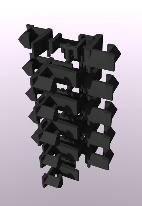
To solve this I have added all the parts onto a sprue, as shown below in the rendering.  The sprue has been drawn to the minimum requirements so as not to waste material or increase cost, and to make it easier to remove the couplings from the sprue.

Short Rapido Replacments Tree Black

The couplings are also available in the Frosted Detail material which is not affected by the new pricing structure.  However, as the model needs to be updated to incorporate the sprue this means the FD price will also be slightly affected. Both kits for 20 and 40 couplings have now been updated ready for the change on the 7th and are still available on the Shapeways site.

My original intention for the couplings was to have a 3D printed product which was delivered ready to use.  And I can still offer that service by order these couplings in bulk myself and offering them for sale from this blog/website.

I can do this by ordering several hundred couplings at once; then it becomes practical to draw things in a different way as Shapeways software is very clever in how it calculates volumes and printability of models.  For example, if I draw two rings, as shown below, interlinked so they cannot be separated, just like a chain, the software will recognize that this is actually one part even though the rings do not touch each other.

3D Rings

By using this advantage I have drawn a cylinder full of holes.  Each hole is not quite large enough for one of my couplings to fall through so once the model is filled with couplings the Shapeways software will only charge for one part.

Rapido Replacments Cylinder

If you would like a pack of 20 or 40, or any other number, of Short Replacement Couplings that are ready to use on delivery I can supply then, please use the contact page or send me an email at Jamestrainparts@yahoo.co.uk.

So you can choose either to order the couplings attached to the sprue direct from Shapeways with their delivery schedule, or you can purchase direct from me which may have a slightly longer delivery time, unless I have that number in stock.

This change in Shapeways pricing policy also affects a few other models of mine but nothing that requires a change like this.

Next week I really do plan on getting back to the HO Scale Union Pacific water tender project and I hope to be able to share with you some photos of the painted car.

A Battery Box For a Con-Cor GE 4500 Gas Turbine

Over the next few months I will be doing some of 3D printed shell designs using the illustrious Con-Cor General Electric 4500 Gas Turbine and making some improvements along the way.  As the NMRA (BR) convention is only six weeks away some of my posts leading up to it might be a bit shorter than normal and so to start with in this post I want to share with you the simplest improvement I have for the Con-Cor Gas Turbine.

Con-Cor GE Gas turbibe

The locomotive, as pictured above, is Con-Cor’s N scale model of the General Electric (GE) 4500 ‘Veranda’ Gas Turbine which was first introduced in 1975.  This model is an excellent performer and consequently has had very few enhancements over the years but there is one detail which is wrong for this model.  Between the four trucks is a fuel tank; however the real 4500 ‘Veranda’ Gas Turbines had a battery box in this location.  Here are some links to images on Railpictures showing the battery box.

Veranda turbine No. 65 helping Big Boy 4020 with a reefer train over Sherman Hill in 1957. (Photo taken by Jack Pfeifer).

Veranda turbine No. 61 pulling a freight consisting of boxcars across Wyoming in 1956. (No photographer listed on slide).  The image is particularly interesting because of the fuel tender behind the locomotive.  Anybody who has followed my work on the pre rebuilt water tenders for the UP heritage fleet might recognize the shape.

These turbine engines did have their own fuel tanks for both diesel and bunker C fuel oil for the turbine but they were positioned inside the main car body.  The diesel fuel powered the donkey engine used to move the locomotive when running light engine and to start-up the turbine prime mover.  UP found that having the main bunker C fuel oil stored inside the locomotive meant that it lost tractive effort as the fuel was used and the weight went down.  Moving the fuel to a larger trailing tender meant the tractive effort remained constant and the range of the locomotive was also increased.  Crews also reported the tenders to be much easer to fill.

The reason Con-Cor have a fuel tank in this location is because the chassis for this locomotive has been recycled from their earlier model of a GE U50 as pictured below.  Ironically the real chassis used to make the U50’s came from recycled Gas Turbines.

Con-Cor GE SP U50

The U50 had a pair of diesel engines for prime movers instead of the turbine requiring more diesel fuel tanks.  GE moved all the batteries and electrical equipment inside the new car body and installed a fuel tank between the trucks.

Con-Cor GE U50-Gas Turbine Chassis

On the con-cor chassis, pictured above, the fuel tank also holds the two inner trucks in place so the simplest thing to do was to replicate the internal shape and add the battery box doors and louvers to the sided.  Below is a rendering of the 3D printed part.

GE Gas Turbine Battery Box Render

The old fuel tank is held in place with one screw; when undone the tank pops off and a new battery box can be put in its place.  Below is an image of the new battery box as it was delivered from Shapeways and an image showing it cleaned alongside the original fuel tank.

Gas Turbine Batter Box - Raw 1 Gas Turbine Batter Box - Clean 7

The new battery box still needs to be painted in UP Harbor Mist Gray to pick out the details of the louvers. The brilliant white of the cleaned FUD is very hard to photograph but already you can see the how it complements the gas turbine locomotive.

Gas Turbine Batter Box - Clean 5

The detail on the side is much clearer in the photo below.Gas Turbine Batter Box - Clean 6

I have made this part available as a single unit or as a pair and you can get them through the links below.

1 UP Gas Turbine Battery Box for Con-Cor Gas Turbine

2 UP Gas Turbine Battery Boxes for Con-Cor Gas Turbines

Here’s the new battery box in situ.

Once I have painted the battery box I will have some more images to share with you.

Drawing a HO Scale Union Pacific Water Tender Part 2

In my last post I shared with you the designs for my HO Scale Union Pacific auxiliary excursion train water tenders; you can find that post here.  Since then the test print has arrived and in this post I’ll show how it came out and the few improvements I have made.

As shown below the kits arrived from Shapeways with the Frosted Detail parts in a transparent form covered in the waxy residue left over from the print process.

HO Tender Kit Raw

I cleaned the parts using Goo Gone to break down the wax, however with this kit being HO it is considerably larger than my normal N Scale parts so a bigger container was needed.  An ice cream tub works very well for this as the lid can be sealed; the Goo Gone will evaporate if it is in an open container.  And I can strongly recommend honey flavour!

Goo Gone Ice Cream Tub

Only the parts printed in FD needed to put in the Goo Gone, the White Strong & Flexible material does not print in the same way and has no waxy residue.

After the cleaning process the FD parts turned opaque and the detail could now be seen as shown below.

HO Tender Kit

This is my first print in the FD material and it came out a little bit coarser than the Frosted Ultra Detail.  This particular model also had a lot more wax build up than I am used to which left a lot of powder on the model from the wax residue, and this needed scrubbing off with a toothbrush.  In the photos below you can still see a lot of the powder around the detail.

HO Tender Detail 1 HO Tender Detail 2 HO Tender Detail 3 HO Tender Detail 4 HO Tender Detail 5

Below you can see the trucks have powder in the holes, clogging the detail.

HO Tender Truck Detail 1

Most of it was easily removed using a toothpick and a toothbrush but there is still more to remove.HO Tender Truck Detail 2

The trucks have been designed to be used with Proto 2000 Wheels as shown below but the distance between the truck side frames is a little too tight so for the test print I have had to use plastic wheel sets from some old box cars.  This has now been corrected in the 3D model as well as the gap you can see between the air cylinder and the pipe.  I have ordered a test print of the new trucks for this model to check the Proto 2000 Wheels work.

HO Tender Wheelsets

As with the N Scale kit the ladders are tied together on a ring which also has the head lamps attached to it, as shown below.

HO Tender Ladder Detail 1 HO Tender Ladder Detail 2

The chassis, tool boxes, flag plates and truck bolsters were all printed in WS&F and all came out well.  The bolster pins are fixed together to help reduce the number of small parts and can easily be cut apart.  HO Tender WS&F Parts

The holes in the chassis for the pins needed to be very slightly drilled out to allow the pins to be a good fit.

HO Tender Chassis  TrucksThe detail on the tool boxes came out very well in the WS&F, it had the level of detail necessary for this part.
HO Tender WS&F Tool Boxes

The chassis fitted into the shell a little too tightly so I have also altered the shell in the 3D model at one end to make for a better fit.

HO Tender Under Side 1

The chassis only fits in one way as each end has a different shape which fits around the coupling connection mounts.

HO Tender Under Side 2 HO Tender Under Side 3Each end of the shell has two pegs to mount a Kadee coupler; I have used No.5 couplers.

HO Tender Coupling 1 HO Tender Coupling 2

The tender still needs some more checking over before I am happy to release it and I also want to check that the new trucks work with the Proto 2000 wheel sets but I think it is just about there.

HO Tender Test Print 1 HO Tender Test Print 2

As I have already said in the previous post the cost of printing in the FUD material led me to test print in the FD material to make the model more wallet-friendly. Having assessed the overall finish of the FD test print the finish is a bit rougher than the FUD so when I do release the tenders for sale I will make them available in both materials to give you the choice.

In a later post I will show you what the FD HO tender looks like painted in the UP colors.

Drawing a HO Scale Union Pacific Water Tender

Back in February 2014 I showed you the drawings and designs for my N scale Union Pacific auxiliary excursion train water tenders. You can find the first post here.  These proved to be very popular and it soon became apparent that modelers in other scales would also like to have the 3D printed model.  In this post I will show you some of the things I have done to turn the N scale model into a HO model.

Below is a pair of the N Scale tenders, as currently run by UP with their heritage fleet.  Some of the details were omitted from the print due to them being simply too small to print and, as is often the case with N Scale, some details needed to be made larger than real life.  A good example of this are the steps at each end and the ladders.UP Water Tenders 1One of the most noticeable details missing from the print were the handrails running along the top.  Several customers have added their own, as shown below on Mark Peterson’s Tenders.

UP Water Tender 4 (Mark Peterson)

UP Water Tender 5 (Mark Peterson)

With the HO kit I wanted to add the missing details in and also improve the scale of the chunkier parts.  HO being at a scale of 1:87 is just about twice the size of N scale which is 1:160.  This means that everything will be, just about, twice the size and therefore the detail will be more defined. However this also introduces another issue.  Re-scaling an N scale model to HO will not simply make it twice the price.

The 3D printers charge by volume of material used or cubic capacity in cm3 to produce the print, plus a fixed charge per print.  So for example, if you had a 1 meter square cube (roughly 3 foot square) it would have a cubic capacity of 1m3 or 1,000,000cm3. If this was printed at 1:160 it would have a cubic capacity of 0.2439cm3.  But if you printed the same cube at 1:87 it would have a cubic capacity of 1.5161cm3 which is significantly higher.

To overcome this there are a few things we can do.  The first thing is to look at the thickness of the parts as these are now all twice the thickness they need to be to print. The 3D printers specify the minimum wall thicknesses which they can print for all their materials.  My N scale water tenders were designed to print in Shapeways Frosted Ultra Detail (FUD) material which has a minimum unsupported wall thickness of 0.6mm.  Details such as the end steps and ladders will be reduced in thickness anyway to remove the chunky look I mentioned earlier, but the biggest difference is made in the large side panels and roof section.  By reducing these thicknesses it greatly reduces the cubic capacity of material in the model.  Below is a section though the N Scale water tender, you can see the thickness of the walls in light blue on the sides and top of the main shell.

UP Water Tender 2007-Present N Inside

After re scaling and adjusting the wall thickness for HO the section looks like this;

UP Water Tender 2007-Present HO InsideThe second thing we can do is look at printing in other materials.  The FUD material is one of the more expensive plastic materials due to the high level of detail that is achievable.  Shapeways also offer a Frosted Detail (FD) material.  This is printed in the same way but the level of detail is slightly less.  FUD can print detail which is embossed or engraved in the parts as small as 0.1mm (0.0039″).  FD can print detail which is embossed or engraved in the parts as small as 0.2mm (0.0078″).  This difference doesn’t sound a lot but in N Scale it is equivalent to 27.2mm (1.07″) and therefore using it for N scale is not practical.

However as we will basically printing an N Scale model at twice the size, printing in the FD material would make sense as the difference in detail will not come into play.  The FD material is cheaper than the FUD which also brings the cost per cubic capacity down.

The third thing we can do is to look at parts of the model which don’t have any detail, such as the chassis, which are required structurally but not cosmetically.  These can be printed in very cheap materials such as Shapeways White Strong & Flexable (WS&F).  WS&F is almost two and half times cheaper than FUD and even though parts in WS&F need to be thicker than in FUD they are still significantly cheaper.

So for the HO Scale UP Water Tender the main body, ladders and trucks will be printed in FD and the chassis, truck bolster pins, tool boxes and flag plates will be printed in WS&F.  I have included the top handrails as part of the main body print.  The ladders are still separately applied details which makes painting easier as they are Harbour Mist gray and not Armor yellow.  Below is a rendering of how they will look.

UP Water Tender 2007-Present HO

The test print has been successfully printed by Shapeways and is due to be delivered to me this week. In a later post I will cover more in-depth details such as couplings and the wheel sets I have used for this model and how they fit, and I will also share with you how the test print came out.

Getting Back on Track

As well as the big 3D printed locomotive shells and parts, I often get asked for small parts and this week I wanted to share with you my design for my smallest yet.  I was asked by a fellow modeller if it would be possible to produce an N Scale Re-Railer to super detail his locomotives.

Re-Railers or Rerail Frogs as they are sometimes called come in all shapes and sizes, typically they are metal castings which are designed to be easy manhandled.  The type I will be looking at is a Y shape with a slot in middle which is designed to straddle the rail.  These are usually carried on locomotives, incase of rolling stock derailment, either on the side of the trucks or slung under the chassis.  They work by straddling the rail next to the derailed train car wheel, then the locomotive either pushes or pulls the car so that the derailed wheel runs up the Re-Railer and back onto the track.  Normally a pair of Re-Railers are used because when one wheel comes of so does the other, the Re-Railers are handed and are designed to work as a pair.

A good photograph of the exact Re-Railer I am modeling can be found here on the translation directory.

Modelling the Re-Railer was not the challenge with this project, that came with the actual size and making it printable at 1:160.  A real Re-Railer is barely 1 Meter (39″) long which in N scale is only 6.25mm (0.24″).  My first draft as shown below was an accurate model of the Re-Railer with some of the details over-sized such as the mounting lugs and flanges to make it printable.

Re-Railer Type 1 Draft 1

However even with the increased sizes the overall part was still unprintable.  The problem lay with the hole in the mounting lug.  In order to get enough material around the hole to make it printable the lugs became unrealistically large, and if the hole was made any smaller it would also not be printable.  To resolve this I also included the mounting bar and corresponding lugs as shown in the images below; these are normally part of the locomotive.

Re-Railer 1

Re-Railers 4

This solved two problems; firstly, by replacing the holes in the lugs with the bar the thickness of the lugs was no longer a problem, and secondly it would be easy to glue the part, once painted, directly to the underside of a locomotive chassis, as illustrated below on one of my DT6-6-2000 locomotives.

Re-Railer on Loco

However this design was also unprintable, but not by much.  The black mounting bar shown in the images above is technically a wire by the 3D printers definition of parts.  This means it has to be twice as thick in order to survive the post print process and to guarantee that it will arrive in one piece.  Where the bar protrudes out of the mounting lugs is okay because this is classified as a detail and is supported by the thickness of the lug. I didn’t want to increase the size of the mounting bar as again it would become too unrealistic so as a compromise I filled in half of the area between the bar and the main body of the Re-Railer as shown below.

Re-Railer Type 1Given the actual size of the part and that it hangs under the locomotive in shadow this will not be noticeable, especially if the raised part of the bar is painted a different color to the filled-in section.

The test print for the Re-Railer has now been completed and is due for delivery later this week.  In a later post I will share with you how it came out and what it looks like on real model.


Replacment Short Rapido Couplings

Having spent the majority of my N scale modeling time in the American arena I have not kept up-to-date with the British N gauge modeling scene. However I’ve recently become involved with the Poole and District Model Railway Society in England who focus on British N gauge modeling and I now have the opportunity to find out what’s been going on.

The Rapido coupling has been an industry standard for more than 30 years in both N scale and N gauge and in this post I wanted to share with you some of the things that can be done to make your older British rolling stock with Rapido couplers look comparable to the new NEM coupled stock.

The majority of American N scale modelers and manufacturers have moved away from the Rapido coupling in favour of knuckle couplings from companies like Micro-Trains, formally Kadee.   British N gauge modelers and manufacturers are now also moving away from the Rapido and using NEM couplers from companies like Dapol and Graham Farish.

The classic Repido pictured below is a very simple but extremely functional coupler.  It allows trains to navigate very tight corners whilst remaining strong and reliable.

Rapido Couplings

Because Arnold-Rapido, the inventors, allowed the design to be freely copied by other manufacturers it soon became the standard for the scale.  As shown above there are many variants to the design but the fundamental parts are all the same. Up until recently Rapido was the industry standard but now technology has moved on and manufacturers have started to introduce new coupling designs which look like the real thing in size and shape.  Initially the new design of couplers still used the Rapido socket and often new rolling stock would come with Rapido couplings installed with the new design coupling in the box to be installed if required.  Now a lot of manufactures only have their new style of couplers fixed to the rolling stock.  With new British stock even the socket has been updated to the new NEM standard socket although the actual Rapido coupling is still in use.

The biggest immediate difference between Rapido and NEM coupled stock is the gap between them.  Below is a photo of some British N gauge coaches made by Graham Farish,  the red GUV or mail express system coaches behind have the traditional Rapido couplers and the Pullman coaches in the front have the new NEM couplers.

Graham Farish Coaches 1

There has to be some gap between the coaches to alow them to navigate corners without becoming buffer locked.  This is when the buffers on the corners of the coach touch each other and prevent the body of the coach from swinging.  With full size trains this is not an issue as the buffers are sprung allowing the buffer to compress and the coach corridor connections to touch.

My first solution is to use my fixed link couplings, pictured below. These fit into the standard Rapido socket on two coaches permanently coupling them together.

Fixed Couplings

By using a shorter fixed link the gap between the coaches is reduced, as shown below.  This is ideal for connecting locomotives together, particularly if they share a DCC decoder as with my E7 DCC conversion, but it is not so good for lots of coaches.

E7 Coupling 2

For short trains with three coaches or less this would work well but for longer trains with, say ten coaches, it would be very hard to transport them if they were all coupled together.

My second solution is to 3D print a shorter Rapido coupling. The standard Rapido coupling has a shank length of 3.5mm as shown below.

Standard Rapido

So I re-drew the Rapido in a range of lengths decreasing by 1/2mm at a time.

Rapido Replacments

Because I wanted these to be cost-effective they have been designed to be printed in the Black Strong And Flexible material offered by Shapeways.  This has three main advantages over the Frosted Ultra Detail material in that it doesn’t need cleaning on arrival, it is already black so they are ready to use right out of the packet and it’s cheaper.  The BS&F material does have a rough finish but this just helps to make them look a bit more realistic.

The first test prints have arrived from Shapeways and have already been successfully tested with Graham Farish coaches.  Although I ordered the full range of sizes all the coaches we tested worked best with the smallest coupler which has a shank length of only 1.5mm. Using a pair of these couplers, one in each coach, it reduced the gap between the coaches by 4mm which in N gauge is a lot.  Below are the same Graham Farish GOV coaches as pictured before but the pair on the left have the new 3D printed Rapido couplers installed.

Graham Farish Coaches 2

The difference was considerable but a test on a corner was required to check for buffer lock.  We used one of the tightest corners on the club’s N gauge layout for the test and as you can see below it was successful.

Graham Farish GOV Coaches On On Bend 3

Below is a close up on the original Rapido couplings.

Graham Farish GOV Coaches On On Bend 2

And below is a close up on the new 3D printed short Rapido couplings.  You can see that the buffers don’t actually meet.

Graham Farish GOV Coaches On On Bend 1

We also tested the short couplings on some Graham Farish Suburban coaches with equal success.  Again the short couplings are between the left hand pair.

Graham Farish Suburban Coaches 1

And a close up of the 3D printed ones.

Graham Farish Suburban Coaches 2

The 3D printed couplings still need to go through a few more tests and I have also made a few tiny improvements to the design to help with the fit into the Graham Farash coaches.  Once complete I will make them available to buy, and I will also offer them for sale in packs of 20 direct from this site.

One of the tests currently going on is looking to see which length 3D printed couplers work best with an N Gauge HST set, but that will have to wait for another post.