Drawing an Alco C-855B for N Scale

Over the last few months I’ve been posting about my new locomotive project, the huge Alco C-855 built for the Union Pacific railroad.  This iconic engine, despite only being in service for 8 years out of North Platte in Nebraska, was part of the general pool of locomotives and ran in different consists with several varieties of Union Pacific power.  But it was delivered by Alco as a set of three; two C-855s and a C-855B cabless booster.  Together they produced 16,500 HP and were Alco’s answer to UP’s call for a loco to replace the ageing GTEL 8500 Gas Turbines.  In this post I’ll share with you my designs for the C-855B to complete the set.

Alco C-855B (Render)

The C-855B is basically identical to the C-855 with the only difference being the lack of a cab at the front end.  As you can see from the images below they are also the exact same length with all the same doors and features.

Alco C-855B Side View

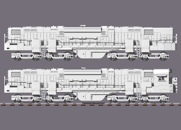
Please note: the trucks are purely there as a representation, I’ve not drawn the proper truck assemblies yet. However I will be doing this so I can make a dummy chassis available soon.

Alco simply removed the cab section and added the same end equipment as the rear end.  Then they filled in the space with bodywork plate as you can see below.

Alco C-855 & C855B Front End

This means that the chassis is exactly the same, well almost.  Because there’s no cab a little bit more will need to be cut off the Con-Cor chassis as it gets wider where the turbine/U50 cab was.

This model is now available in both Shapeways FUD and FXD materials and can be found here.

The brass Additions for this locomotive are not the same as the C-855, the front handrails are different as well as the quantity of grab irons etc, so I’ve drawn a new sheet.  These will be available very shortly but if you wanted to pre-order them or both the C-855 and C-855B brass Additions it will give me a better idea of how many sheets I need to order later this week.  Please send me a message via the contact page or email me if you want to order any brass Additions.

The chassis and assembly instructions for both the C-855 and the C-855B are almost done and, once complete, I’ll be adding them to the site in a PDF format which you can download.  There are a few cuts that need to me made to the chassis in order to fit the shell and the exact dimensions will be included.

Together all three will look very impressive and I am greatly looking forward to seeing them all run.

Alco C-855 Triplents (Render)

My two C-855s are still at the painter’s but hopefully I’ll have some more pics to share with you soon.

In the meantime here are some photos from two customers who have already started painting theirs.

Brian Stewart has re-powered his chassis with an Atlas motor.

Alco C-855 1(Brian Stewart) Alco C-855 2(Brian Stewart).JPG Alco C-855 3(Brian Stewart).JPG Alco C-855 4(Brian Stewart).JPG

Mike Musick has primed his ready for the brass Additions and final paint.

Alco C-855 1(Mike Musick).JPG

If you have any work-in-progress photos or some of the finished locomotives running on your layout and you’d like to send them to me I’d be happy to add them to the site gallery.

A New Pilot for an N Scale EMD DD35

My N Scale kit for Electro Motive Division’s DD35 locomotive uses Bachmann’s massive EMD DDA40X chassis, after some shortening.  But as there’s something not quite right about the pilot on the Bachmann model, in this post I will share with you my designs to add a new body-mounted pilot to the DD35.

All of the real EMD ‘DD’ locomotives use four axle trucks which rotate under the chassis. The pilot, which holds the coupling and multiple unit connections, is part of the main chassis, or body, of the locomotive.  This means that as the locomotive runs around a curve the truck rotates but the pilots remains square to the body.  This is done so the load from the coupling is transferred through the chassis and not through the truck mounting. In this image, from Railpictures taken by Tom Farence, you can see the steps and pilot area are square to the body even though the loco is on the bend.

Bachmann’s model of the DDA40X has the pilot attached to the truck causing it to swing out from under the body on curves, as you can see below in this image of a DD35 between a GP38 and an SD35.

DD35 & Friends 4

This also creates a gap between the steps and the body which is, and looks, un-prototypical.  You can see the steps in the image below disappearing under the shell.

SP DD35 9902 8

So why is the pilot located on the truck? Well Bachmann did it for a good reason.  Because the DDA40X locomotive is so long, without the pilots being on the truck it simply wouldn’t be able to navigate the tight curves, which many of us have on our model railroads, without pulling any connected cars off the track.  Curves on prototypical railroads have a much larger radius and they don’t suffer from this issue. The Bachmann DDA40X can actually traverse some very tight curves but it does look odd doing it.

However there are a few modelers that have the luxury of large minimum radius curves on their layouts and have requested a modification be made to my DD35 kit.  Because I already offer the kit in powered and dummy forms using the same shell I didn’t want to created a whole new shell just for this and, luckily, there is a solution.  The dummy DD35 kit, as pictured below, comes with 3D printed trucks that include a pilot.

DD35 Dummy Pilot

The truck and pilot behave in the same manner as the Bachmann one on the powered chassis and have the same appearance so you can run a powered and dummy unit together.

By extending the pilot section up to meet the underside of the 3D printed dummy chassis or the Bachmann metal chassis, the new pilot can be fixed directly to the body, leaving the trucks free to rotate.

DD35 Dummy Pilot 2

The new pilot section, as pictured below, has been shaped so it will fit the sloping 3D printed dummy chassis or the Bachmann metal chassis, and it has the same mount for a Micro-Trains body mount coupler.

DD35 Dummy Pilot 4

The MU hoses are printed as part of the pilot but can easily be cut off with a craft knife or sanded off if you prefer to fit etched brass ones.

The new pilots are available in two packs.

One pair of N Scale EMD DD35 body mount pilots

Two pairs of N Scale EMD DD35 body mount pilots

Please remember when fitting your N Scale DD35 with a body mounted pilot and coupling it will increase the minimum radius that your locomotive can navigate.  If you are unsure if this will work for you, position your DD35 over your tightest curve and see where the nose of the body swings out to.  If it is outside the sensible condition to be able to couple up to a another car or locomotive then your radius is too small.

I will also be making a similar pilot available for the N Scale EMD DDA40X which I’ll share with you soon.

Designing an Enclosure for DCC Sound Decoder Speakers Part 2

In last week’s post I shared with you my designs for a stackable enclosure that allows you to build any height sound box for your DCC speaker.  You can find the post here.

This week the parts have arrived from Shapeways and I thought I would show you how they came out.  Right out of the box the parts are transparent and look like this.

Speaker Enclosure Prts Raw.

The hollow parts are the wall sections and the closed off parts are the bases  As with all parts printed in the Shapeways Frosted Ultra Detail material they need to be cleaned up to remove the waxy residue left behind from the printing process.  This is done by soaking the parts in Goo Gone overnight.

Once the parts have had a good soak they are rinsed off with water and left to dry.  As they dry they will turn opaque and can now be painted if required.  If you dont clean off the waxy residue it will prevent paint and glue from adhering to the surface of the part.

With all the parts clean and dry it was time to do some test fitting.  As designed, they all fit together perfectly, and with a spot of glue will be come a solid enclosure.  The Zimo speaker is also a perfect fit; it actually fits better into the 3D printed part than it does into the injection molded enclosure it came with.

Speaker Enclosure Base plus 2

The depth of the enclosure can now be easily adjusted by 1.5mm by adding or subtracting a wall section.

Speaker Enclosure Base Plus 3

These means you can create any size enclosure that you need.

Speaker Enclosure Base Plus 11

It even fits into the base on its own should you be very tight on space.

Speaker Enclosure Base

The next stage is to do some testing to see how it sounds compared to the stock enclosure.  As a comparison here is a video of the stock speaker that comes with the decoder.  You can hear the engine running and me sounding the horn.

Next we have a video with the Zimo speaker fitted on its own.  A word of warning; the speaker is designed so that you can solder wires to it, but remember a speaker has a powerful magnet inside and if you are not careful it will attach itself to the soldering iron and get very hot, causing damage to the speaker.

The speaker on its own is very quiet as there is nothing behind it for the sound to bounce off.

Then we have a video showing the Zimo speaker with and without the stock enclosure.  When the speaker is lowered onto the enclosure the volume gets much louder.

And finally we have the Zimo speaker and the 3D printed enclosure made from three wall sections.  The volume increase using the 3D printed parts is roughly the same as the stock enclosure.

The parts that made up this enclosure were not glued together for the test so the sound should get even better once they are all sealed up.

I will shortly be making these speaker enclosures available via Shapeways and through my blog where you will be able to get them in different quantities.

Designing an Enclosure for DCC Sound Decoder Speakers

There are now many options for adding sound to DCC locomotives but, with the limited space often found inside N Scale locomotives, fitting in all the parts can be a problem.  Apart from the actual DCC decoder the speaker is one of the larger problems and in this post I will share with you my design for a customizable speaker enclosure.

When you buy a DCC sound decoder it normally looks something like this.

SDN136

This sound decoder, model SDN136, is made by Digitrax and is designed to fit into N Scale locomotives.  The standard 8 pin plug is attached to the wires coming out of the left hand side.  The right side has wires attached to the speaker and a capacitor which is used to keep continuos power to the decoder when crossing dirty track.  This prevents the sound from stuttering.

The speaker has a sticky area with white peel-off paper. This can be stuck to the inside of a locomotive shell, preferably in an area which has some holes to allow the sound to come out.  Although this works it can be very quiet as the speaker is small and not capable of making lots of sound.  Or it may simply sound tinny.

To improve the sound volume the speaker can be placed inside an enclosure.  This works in the same way as speakers used for home stereo systems. The speaker is fixed to the front of the enclosure facing outwards. The air inside the enclosure acts like a spring returning the speaker cone to the ‘zero’ position more efficiently than if it was surrounded by open space.  Not only does this reduce noise from the back of the speaker but it amplifies the sound from the front.

Several companies sell speakers already mounted on enclosures and these can easily be used to replace stock speakers.  However the speaker is now getting bigger and finding space for it can be an issue.

A speaker which has been regularly used by members of my local club is the Zimo LS8X12.  This speaker comes with an enclosure as you can see in the images below.

Zimo LS8x12-1

The speaker simply fits into the recessed top of the enclosure.

Zimo LS8x12-2

Because the enclosure is fairly deep by N Scale standards, it doesn’t fit into some of the locomotives. To get around this the modeller tends to file or cut down the enclosure.  Because it is tapered this then creates the problem that the speaker no longer fits properly and may leave gaps around the edge preventing the enclosure from working effectively.

To solve this I have designed an enclosure that is built up in layers allowing the modeller to make it as deep as they want in 1.5mm steps.

Zimo Speaker Enclosure 1

The enclosure is made from two different types of part.  The first is the base and the second is a wall.  They are both shown below from top and bottom. The recesses in the tops of both allow the speaker to be fitted, even in the base.

Zimo Speaker Enclosure 2

The walls push together creating a 1.5mm extension to the enclosure.  Once it’s at the required size the speaker will simply fit into the top wall section.

There is a tolerance gap between the flange that fits them together to allow a small amount of glue.  This will hold the parts together and ensure a good airtight fit.

I have now ordered a test set of these enclosure parts in Shapeways ‘Frosted Ultra Detail’ material and I should have an actual working enclosure to share with you soon.

Repairing an N Scale Minitrix Steamer

The German firm Minitrix, now owned by Markin, used to produce a range of US and UK steamers as well as their native German locomotives.  Most of these early models date back to the 1970s and are still running strong.  However there are a few parts that are prone to breaking and in this post I will share with you how to repair the crank pin on a Britannia class locomotive.

Minitrix used the same chassis or a variation of the chassis on a variety of locomotives.  In the US it was the 4-6-2 K4 and 2-10-0 Decopod.  In the UK it was the 4-6-2 7P Britannia, 4-6-2 A3, 4-6-2 A4 & 2-10-0 9F class engines.  These all had metal side rods, drive rods and eccentric cranks but the eccentric pin that holds it all together is plastic.  And it’s this part that has been known to break. If you look at the model in the picture below I have circled the crank pin in red. The side rod connects all three driving wheels together and is the nearest to the wheel.  The connecting rod or main rod is fixed to the center wheel and runs into the cylinder.  The crank pin holds the connecting road and side rod to the center wheel.  The eccentric rod connects to the cranked end of the pin and drives the valve gear in the cylinder.

Minitrix Crank Pin 1

The crank pin is designed so that the side rod and connecting rod can easily rotate without binding on the pin but are also held in place. So you can see how this works I have modeled the crank pins below.  The square shaft on the end of the pin fits into the wheel.  Because it’s square this will ensure it will rotate with the wheel. The side rod and connecting rod fit over the round section and are held in place by the wheel and cranked top.  The holes in the side and connecting rods are larger than the pin to allow free moment.

N Scale Minitrix Crank pin

What normally happens is the metal rod assembly becomes jammed and the weakest point is the plastic crank pin. The pin breaks where the round section meets the square section and falls out.  The connecting rod then flails about and can become bent.  With this 4-6-2 that is exactly what has happened, although luckily the connecting rod wasn’t bent.

Minitrix Crank Pin 2

So to fix this engine the first thing needed is a new crank pin.  Spare parts for these engines ran out years ago so my next option is to 3D print one.   I printed some using the 3D model above in Shapeways Frosted Extreme Detail material.  It will also print in their Frosted Ultra Detail material.

Minitrix Crank Pin 3

Next the old square section on the crank pin needs to be removed.  For this I used a small drill in a pin vice as you can see below.  I selected a drill that was a bit smaller than the pin.  Once I had drilled through the pin the remaining materiel was so thin and weak it pulled out with a pair or tweezers.  You can see the remains of the pin under the new one.

Minitrix Crank Pin 4

In the image below you can see the old and new parts next to each other.  The old crank pin is connected to the eccentric rod by a metal pin which has a flared end and cannot easily be removed.  One option is to cut off the old plastic crank and un-flare the end of pin hoping to fit it into the new one.  However that is very hard to do.

Minitrix Crank Pin 5

To make this job easier I did cut off the old plastic crank but I did not un-flare the pin.  Instead, using a very sharp craft knife, I cut through the loop on the end of the new crank pin.  This then forms a C shape although the two ends still touch.  Carefully spreading the new C shape I was able to push it over the metal pin as you can see below.

Minitrix Crank Pin 6

The connecting road and eccentric rod were then refitted to the loco.

Minitrix Crank Pin 7

The new crank pin simply push-fits into the driving wheel, ensuring it passes through the hole in the connection and side rods.

Minitrix Crank Pin 8

It is important to make sure the crank pin is pointing in the right direction, which is towards the center of the wheel.

Minitrix Crank Pin 9 Minitrix Crank Pin 10

The next part is to test the the new assembly and what could be better than running it on a layout.  Below is short video of the engine running demonstrating that the new crank pin works perfectly.

The rocking motion is caused by the traction tires as the loco is supposed to be moving.

The last thing to do is to add some silver paint to the new crank pin to help blend it in.  It’s best to put on as little as possible as you don’t want to paint the parts together or cause a bind.

Minitrix Crank Pin 11

A pack of four replacement crank pins is available from Shapeways here.

Alternatively if you would like this repair made to your locomotive for you, you can contact me though the contact page or directly at jamestrainparts@yahoo.co.uk and we can arrange to get it done.

Drawing an Alco C-855 for N Scale Part 3

Earlier this year I shared with you my plans for my new N Scale Alco C-855. You can read parts one and two here and here.  I have recently started to do more work on the project  and have test printed the 3D printed parts which will extend the chassis for the new locomotive.  In this post I will share with you how they came out.

As discussed in my previous posts the chosen chassis, as modeled below, for the C-855 is going to be Con-Cor’s 4500 Gas Turbine/GE U50 chassis.

Con Cor 4500-U50 Chassis Render 6

This chassis needs to be extended, as shown below, because although the C-855 uses the same trucks they are spaced further apart.

Alco C-855 Chasses 2

The chassis needs to be extended by 10mm and ideally in the middle over the motor.  To do this I have designed a complete replacement section that will extend the chassis and clamp the motor keeping it in the correct place.  Below is a rendering of the new parts.

Alco C-855 Chasses 4

These have been designed to be printed in stainless steel.  Although this metal is more expensive to get printed than plastics I didn’t want to reduce the weight of the chassis as this would have a negative effect on the locomotive’s tractive effort.  As the C-855 chassis will be longer it should now be heavier which will hopefully add to the tractive effort.  The C-855 did have 1000 more horsepower than the 4500 Gas Turbine and 500 more than the U50 after all.

The new extenders were printed by Shapeways and arrived ready to use as you can see below.

C-855 Chassis Extenders 1

In close up shots like this you can see the layering effect caused by the 3D print process; this is more pronounced than on some other materials as the layer thickness is greater with stainless steel.  Shapeways also offer this material polished which removes these lines but as the parts will not be visible once the locomotive is complete this did not seem necessary.

C-855 Chassis Extenders 2

A small change to the parts from the rendered view above is the introduction of wire routes.  This allows the bottom motor wire to run up between the shell and the chassis. For DC this is not necessary but for DCC the motor feed needs to be isolated from the chassis and a wire used to connect the motor to the DCC decoder.

C-855 Chassis Extenders 3

Just to show that these really are metal, below is a photo of a basic volt meter set to measure continuity.  One of the parts has been laid across the pins.  As you can see the meter is reading 100%.

C-855 Chassis Extenders 12

The parts will also be available in the cheaper plastics.

I did not allow any fitting gap between the motor and the new chassis parts.  Because they have been printed to such a high level of accuracy the hole for the motor is the exact same size as the motor and consequently it won’t fit.  This is easily remedied by grinding some of the inside of the chassis away. Alternatively I could have shaved down the motor casing.  I ground the inside of the parts with a flat stone in an electric modeling drill. Simply grinding the surface flat and removing the layering effect was enough for the motor to fit.

C-855 Chassis Extenders 4

The motor now fits and I have also updated the 3D model to make the fit a bit easier.

C-855 Chassis Extenders 5

As well as extending the chassis both drive shafts needed to be extended by 5mm as the ends will no longer reach the gears on the motor.  To do this I designed a 3D printed gear extender that will fit into the existing drive shaft gear as you can see in the rendering below.

Alco C-855 Chasses 9

The new part has been designed to be printed in Shapeways Frosted Detail plastics.  This is the best material to ensure the accuracy of the gear teeth.  My set was printed in Frosted Extreme Detail and below you can see how they came out.

C-855 Chassis Extenders 7 C-855 Chassis Extenders 8 C-855 Chassis Extenders 9 Test fitting them into the original gears was a perfect push fit.  Below you can see one fitted into a drive shaft.  When it is time to fully assembly the locomotive I will put a small dab of super glue between the parts just to ensure they stay together although friction will do the job.

C-855 Chassis Extenders 10 C-855 Chassis Extenders 11

The next task is to finish the 3D model for the main body shell and set-out all the brass Additions.  My other locomotive kits have brass Additions for handrails and parts as well as 3D printed handrails but for this locomotive the only handrails will be brass.  I decided to do this because there will be lots of finally detailed handrail parts and if they are printed in plastic they are still a bit oversized and are very fragile.  With brass etching I can get decently sized handrails as well as lots of other details such as grab irons and roof top walkways.  Once I get the drawings done I will be sharing them with you.