Last month I shared with you my design to contain lots of replacement short Rapido couplings inside a cage-style container. You can find the post here. In this post I wanted to show you how it all came out.
The reasons for making this cage were to firstly keep the hundreds of small parts contained and secondly to reduce the cost of the parts. These have been printed by Shapeways and their new pricing structure, although reducing the cost of their Black Strong & Flexible material, now takes into account a fee per individual part. So as you can imagine, printing several hundred loose parts will incur a hefty fee. To counteract this the cage was designed so that it used the least amount of material but did not have any holes large enough for the parts to fall out: therefore Shapeways treat it as one item when pricing it for printing.
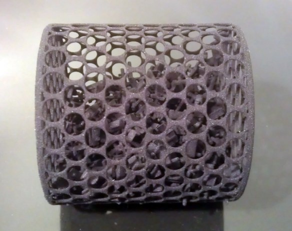
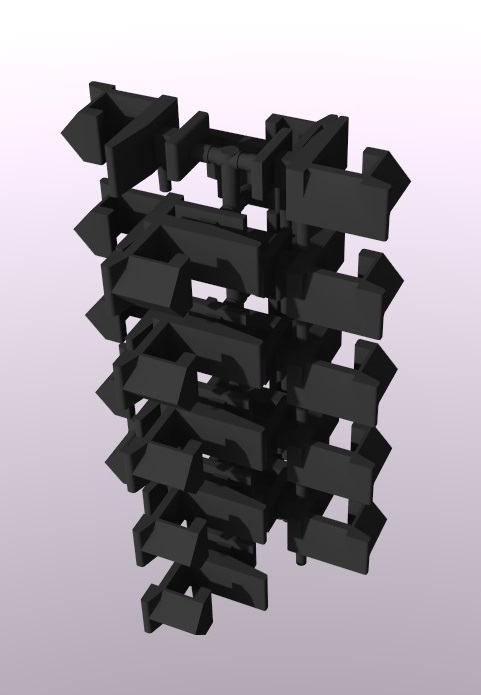
This particular cage has been designed to hold 240 short Rapido couplings, in the computer model the cage appears densely packed, as shown below, allowing for the spacing between each part. This is because there has to be a minimum gap between each part, otherwise they could be unintentionally joined together by the 3D printer.
When the actual print arrive it appeared to be only half full. This is because once the support material which provides the spacing had been removed all the couplings fall to the bottom of the cage.
The cage structure is, as the name of the material suggests, very flexible and can easily be squeeze in the middle sections where the material is at its thinnest but it retains its strength and springs back into shape. The end rings forming the 90° corners are strong however that is more to do with the design of the structure.
To remove the couplings I used a pair of side cutters to cut out a section from the top; then they could be emptied out as required.
This is a very effective method of printing hundreds of these couplings at once without the need to mount them on a sprue thus removing the need to cut them off before they can be used.
This container of 240 couplings is available through my Shapeways here.
I also offer these replacement short Rapido couplings in packs of 20 for £5. Please contact me through the contact page or you can email me directly at jamestrainparts@yahoo.co.uk if you would like a set, or more.
This weekend just gone I was at another train show, November is a busy month for shows here in the UK, and in next week’s post I will show you some of the layouts at the show.
In last week’s post I released my designs for short replacement Rapido couplings to reduce the distance between coaches on N Gauge rolling stock. You can find the post here. Since my post Shapeways have announced their new pricing structure which will be rolled out on the 7th of October. For the most part the changes are an improvement because several materials will be come cheaper to print in. However, due to a complication with the Short Rapido Couplings model, it will become impractical to print the model as it is. In this post I will share with you what changes I am making to continue to supply these couplings.
The default material for these parts is Shapeways Black Strong & Flexible. It is one if the cheaper materials, ideal for parts like this which have a lower level of detail but which still need to be functional. The new pricing structure for BS&F will now charge a fee for each part in the model, consequently with a pack of 20 couplings this makes the model impractical.
To solve this I have added all the parts onto a sprue, as shown below in the rendering. The sprue has been drawn to the minimum requirements so as not to waste material or increase cost, and to make it easier to remove the couplings from the sprue.
The couplings are also available in the Frosted Detail material which is not affected by the new pricing structure. However, as the model needs to be updated to incorporate the sprue this means the FD price will also be slightly affected. Both kits for 20 and 40 couplings have now been updated ready for the change on the 7th and are still available on the Shapeways site.
My original intention for the couplings was to have a 3D printed product which was delivered ready to use. And I can still offer that service by order these couplings in bulk myself and offering them for sale from this blog/website.
I can do this by ordering several hundred couplings at once; then it becomes practical to draw things in a different way as Shapeways software is very clever in how it calculates volumes and printability of models. For example, if I draw two rings, as shown below, interlinked so they cannot be separated, just like a chain, the software will recognize that this is actually one part even though the rings do not touch each other.
By using this advantage I have drawn a cylinder full of holes. Each hole is not quite large enough for one of my couplings to fall through so once the model is filled with couplings the Shapeways software will only charge for one part.
If you would like a pack of 20 or 40, or any other number, of Short Replacement Couplings that are ready to use on delivery I can supply then, please use the contact page or send me an email at Jamestrainparts@yahoo.co.uk.
So you can choose either to order the couplings attached to the sprue direct from Shapeways with their delivery schedule, or you can purchase direct from me which may have a slightly longer delivery time, unless I have that number in stock.
This change in Shapeways pricing policy also affects a few other models of mine but nothing that requires a change like this.
Next week I really do plan on getting back to the HO Scale Union Pacific water tender project and I hope to be able to share with you some photos of the painted car.
Earlier this year I shared with you my designs for a shorter coupling to replace the standard Rapido coupling. You can find the post here. The idea was to bring rolling stock closer together to increase the realistic look, in particular this was aimed at an N Gauge High Speed Train (HST) set. In this post I will show you how the HST set looks with all eighteen couplers replaced.
The HST or Intercity125, as seen here, is a very iconic British train. First introduced in 1975 and with a top speed of 148 miles an hour it is still the world record holder as the world’s fastest diesel-powered locomotive or train. Although several are now approaching 40 years old many have been re-powerd and refurbished and are still in regular revenue service. Originally they were all owned by British Rail but since the privatization of the railways they can be seen in a variety of colors and liveries around the UK.
The HST has two power cars, one at each end, and eight or sometimes nine Mark 3 coaches between them. The whole set is coupled together with US style buckeye couplers, as shown here, and flexible corridor connections, as shown here.
Models of this train in N gauge have been made by several manufactures and improved over the years. Graham Farish is one such manufacture and it is their HST in CrossCountry livery that I have used to test the first set on.
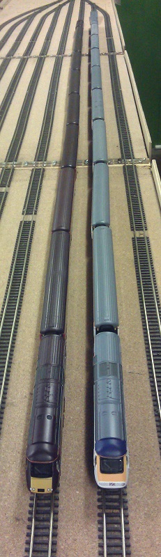
As a comparison I have used a second HST set in First Great Western livery, shown below, with standard Repido couplers.
Starting in the storage siding I lined up both HST sets; this clearly showed how reducing the coupling lengths not only closed up the gaps between the coaches but also reduced the length of the train.
The new couplings fit into the existing Rapido socket and work in the same way. Below you can see how far the original Rapido couplers protrude from the First Great Western set. Oddly enough the First Great Western set also have buffers on the ends of the coaches; this is actually a mistake as the HST sets do not have them. Almost all English rolling stock does, or did, have buffers, but as the HST sets only run in fixed rakes and only use the buckeye couplers, buffers are not required.
Because of these buffers, using the new short couplings with the First Great Western set might cause a problem commonly known as buffer lock. This happens as the coaches navigate tight corners and one buffer rides over the other: when the train returns to the straight track it can not pull the buffers apart. To solve this problem the owner of the First Great Western set is going to remove the incorrect buffers before he fits the new short couplers.
Up close the difference is very clear to see and this improvement to the coaches makes them look far more realistic. It would be possible to close the gap even more but this would prevent the coaches from going around any corners at all. As the coaches enter the corner the gap on the inside of the curve will close up, the tighter the curve the more gap you need. The CrossCountry HST set has been tested on the tightest corners on the Poole & District Model Railway Club’s N Gauge layout without any issue.
These 3D printed couplings will also work with standard Rapido couplers because they are exactly the same shape.
To show just how good the overall effect is, here is a short video on the CrossCountry HST running in the Poole & District Model Railway Club’s N Gauge test track.
Here is another video showing both HST sets crossing the bridge.
The 3D printed couplings are available in Shapeways Black Strong & Flexible material, as shown in the examples above, and the Frosted Detail Material. With the BS&F they are ready to use right out of the packet although they do have a slighty rough finish which I think makes them look better. The FD couplings will have a smoother finish but they will need to be cleaned and painted.
Here’s one more short video of the CrossCounty HST dashing through the countryside.
Next week I will be back with the HO Scale Union Pacific water tender project and hopefully I will be able to share with you some photos of the painted car.
A few months ago I shared with you the replacement drive shaft I 3D printed for my N Scale MDC/Roundhouse 2-8-0 steam locomotive, you can find the post here. Since then I have picked up an N Scale Atlas Pennsylvania Railroad 4-4-0 with a broken drive shaft. The intention was also to 3D print a repair. In this post I will show you what I did.
The Atlas 4-4-0, as pictured below, was introduced in 2013 and is a fantastic model. Given the size and limited weight it has a lot of tractive effort. This, as with Roundhouse’s 2-8-0, is because the motor is located in the tender and connected to the all metal locomotive body by a plastic drive shaft.
Each end of the plastic drive shaft has a ball which fits into a socket, giving the necessary movement to allow the tender to navigate bends as the drive shaft is turning. Each ball has two pegs protruding at 90° to the drive shaft, the sockets have slots to receive the pegs. Thus, as the shaft rotates the pegs rotate the sockets.
With this particular locomotive its the plastic socket part that has broken. This part has the ball socket and slots at one end and a hole through the other. The part is press fitted onto either the metal drive shaft coming out of the tender or the metal drive shaft entering the back of the locomotive. As the hole in the part is ever so slighty smaller than the metal drive shaft it is held in place by the natural clamping and friction caused by the undersized hole. For some reason the plastic socket has split in two, as shown below. The metal drive shaft entered from the left of the socket.
To repair this locomotive all I really needed was one new plastic socket part however it occurred to me that this may not be the only example of this happening so I drew up a replacement pair of plastic drive shafts and sockets as shown in the rendering below. This means all bases are covered and there is a spare drive shaft incase a peg breaks off the first. Given that the Shapeways FUD material is more brittle than regular injection molded plastic it is possible that by removing and inserting the drive shaft many times into a socket, a peg could break off.
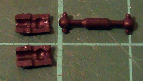
The parts arrived from Shapeways and after cleaning looked like this.
Comparing the new parts to the orignal, as pictured below, you can see the new drive shaft is just a fraction longer. This didn’t have an effect on the locomotive but it has been corrected in the 3D model.
When I modeled the plastic socket part I intentionally made the hole for the metal drive shaft too small. Once the part had been cleaned and all the excess powdery material had been removed I enlarged the hole using a 1.6mm Ø drill in a pin vice.
This hole was still very slightly smaller than the metal drive shaft so I was very careful not to over do it when I pushed it onto the shaft. I used a pair of needle nose pliers to apply the pressure whilst securing the locomotive between my fingers.
I resembled the locomotive using a new 3D printed drive shaft and it all fitted perfectly. I then removed the new drive shaft and installed the original as this was already black in colour. This also fitted perfectly into the new 3D printed socket. I didn’t paint the 3D printed parts, however as long as you don’t apply the paint too thickly inside of the socket or on the ball it should not be a problem if you do. If you do paint the parts I recommend lubricating the ball joints with a non corrosive grease such as Labelle Lubricants No. 106. This will prevent ware and reduce any resistance caused by the paint, resistance will drain power from the motor.
To see how well the repaired locomotive worked I took it down to my local club, the Poole & District Model Railway Society, to run it on their test layout. Don’t forget, on the videos you can turn up the quality by clicking in the gear wheel at the bottom right of the window once the video has started.
Here we see the little 4-4-0 pulling a local passenger train. If you look closely at the first video you can see the white of the 3D printed socket just under the cab floor.
And here it is again with a lumber train, these log cars are also 3D printed, they where special cars built only for Yosemite Valley Railroad. You can read more about the log cars here.
The slow motion of the locomotive was also unaffected, I havent added any lubricant yet but if I do it can only be an improvement.
My biggest concern was that under a heavy load the traction tires would prove to be stronger than the friction between the replacement 3D printed parts and the metal drive shaft, causing the 3D printed socket to spin on the metal drive shaft. But my mind was put at rest when the little 4-4-0 trundled off with a train of 13 box cars and a caboose!
The repair is a success and I you need to repair your Atlas 4-4-0 drive shaft can get the repair kit here.
I leave you this week with one more short video of the repaired Atlas 4-4-0. This locomotive will shortly be converted to DCC, re-spayed and re-numbered to be Sierra Railroad No.7 , sorry Pennsylvania Railroad fans. But you may be pleased to here I will be brining out a much bigger Pennsylvania Railroad locomotive very soon.
At the end of July I shared with you my designs for my N Scale Type 1 hanging Re-Railer, you can find the post here. This detail part was designed to fit onto the underside of locomotive frames, as shown below. In this post, as promised, I want to share with you my design for my Type 2 truck mounted Re-Railers.
The truck mounted Re-Railers were commonly used on switching locomotives but also on road locomotives. Here is a link to a photograph on railpictures.net of UP’s GP20 locomotive No.475, taken by Joe Blackwell, carrying truck mounted Re-Railers.
These Re-Railers are much smaller than the Type 1s as they don’t straddle the rail. This makes them much easer to handle by the train crews. They are designed to be put on either the inside or outside of the rail, in front of the de-railed wheel set. Again they work in pairs so one is need on each rail. The locomotive will then push or pull the de-railed car back up the Re-Railer onto the track. Here is a rendering of the Type 2 Re-Railer.
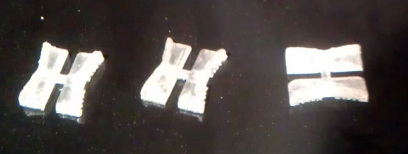
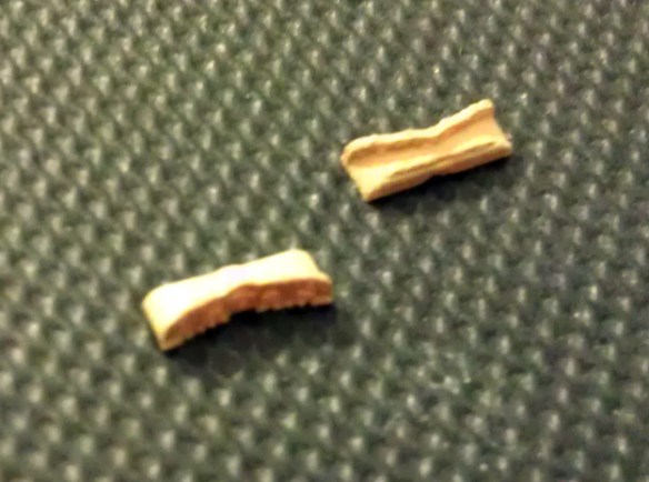
Because these are so small I have had to print them in pairs, joined together by a small strip of material as shown below. The Re-Railers measure just 5.2mm (0.204″) long.
Once cleaned and painted the detail starts to come out including the toothed edge and holes in the casting which you can see on the rendering above.
As with the Type 1 Re-Railers I brush-painted them using a basic matt yellow acrylic paint.
The ideal locomotive to test these on was my Life-Like UP GP20. Although the new Re-Railers are a bit bright, with some weathering they will look right at home.
If you want to super detail your own locomotives these Re-Railers are available in 3 different packs from my Shapeways shop or by clicking on the links below;
A helpfull hint for cleaning these parts under running water is to use a bowl or plug the sink, if the water grabs them they will go straight down the drain!
Next weeks post will be about some larger 3D printed parts, given that these Re-Railers are the smallest item to date that won’t be hard.
Over the next few months I will be doing some of 3D printed shell designs using the illustrious Con-Cor General Electric 4500 Gas Turbine and making some improvements along the way. As the NMRA (BR) convention is only six weeks away some of my posts leading up to it might be a bit shorter than normal and so to start with in this post I want to share with you the simplest improvement I have for the Con-Cor Gas Turbine.
The locomotive, as pictured above, is Con-Cor’s N scale model of the General Electric (GE) 4500 ‘Veranda’ Gas Turbine which was first introduced in 1975. This model is an excellent performer and consequently has had very few enhancements over the years but there is one detail which is wrong for this model. Between the four trucks is a fuel tank; however the real 4500 ‘Veranda’ Gas Turbines had a battery box in this location. Here are some links to images on Railpictures showing the battery box.
These turbine engines did have their own fuel tanks for both diesel and bunker C fuel oil for the turbine but they were positioned inside the main car body. The diesel fuel powered the donkey engine used to move the locomotive when running light engine and to start-up the turbine prime mover. UP found that having the main bunker C fuel oil stored inside the locomotive meant that it lost tractive effort as the fuel was used and the weight went down. Moving the fuel to a larger trailing tender meant the tractive effort remained constant and the range of the locomotive was also increased. Crews also reported the tenders to be much easer to fill.
The reason Con-Cor have a fuel tank in this location is because the chassis for this locomotive has been recycled from their earlier model of a GE U50 as pictured below. Ironically the real chassis used to make the U50’s came from recycled Gas Turbines.
The U50 had a pair of diesel engines for prime movers instead of the turbine requiring more diesel fuel tanks. GE moved all the batteries and electrical equipment inside the new car body and installed a fuel tank between the trucks.
On the con-cor chassis, pictured above, the fuel tank also holds the two inner trucks in place so the simplest thing to do was to replicate the internal shape and add the battery box doors and louvers to the sided. Below is a rendering of the 3D printed part.
The old fuel tank is held in place with one screw; when undone the tank pops off and a new battery box can be put in its place. Below is an image of the new battery box as it was delivered from Shapeways and an image showing it cleaned alongside the original fuel tank.
The new battery box still needs to be painted in UP Harbor Mist Gray to pick out the details of the louvers. The brilliant white of the cleaned FUD is very hard to photograph but already you can see the how it complements the gas turbine locomotive.
The detail on the side is much clearer in the photo below.
I have made this part available as a single unit or as a pair and you can get them through the links below.


You must be logged in to post a comment.