More 3D Printed Replacement Horns

Earlier this year in March I shared with you more of my designs for 3D printed replacement horns; you can read the post here.  I have now designed and test printed a few more and in this post I will share them with you.

My latest horn is a simple single chime horn intended to replace some missing ones on my set of Alco FA units.  The design, as pictured below, is fairly simple, consisting of a horn with a locating peg protruding from the underside.

Single Chime Horn Render 1

These parts, as you might expect for N Scale, are very small and although they are printable the chance of them getting lost in the cleaning and shipping process at Shapeways is very high, so they have been added onto a sprue, making a set of 6.

Single Chime Horn Render 2

They can be cut off the sprue just above the horizontal bar. There is a collar under the horn so that when the peg is fitted into a hole in the cab roof they won’t drop too far onto the locomotive.  As with all my horns they were designed to be printed in Shapeways Frosted Ultra Detail material.  However, now that Shapeways have introduced their Frosted Extreme Detail material I opted to get them printed in this.  The cost difference is small between FUD and FXD for such a small part but there is a longer wait time of 12 days for FXD; this is because it takes longer to print.  I believe the extra time is worth it as they have come out very well.  These only turned up in the mail today so they are still coated in the waxy residue, although I have noticed recently that Shapeways’ models seem to be less coated than they used to be which is a good thing.

Single Chime Horns 1

These models are now in the Goo Gone for an overnight soak which will break down the waxy residue and turn the parts opaque.  Once removed and dried then they can be painted and fixed to my locomotives.  Just to give you an Idea of scale, below is a shot of the sprue of 6 on top of an N Scale Micro-Trains FT locomotive that’s also awaiting a new set of horns.

Single Chime Horns 2

I know they look a bit odd still attached to the sprue but leaving them attached for now makes them much easier to fish out of the Goo Gone.

Single Chime Horns 3

Now that I have four different types of replacement horns to offer it has become apparent to me that I need to change the way I have named them, particularly as I have some more designs coming soon as well.

So the new name will consist of 2 numbers separated by a dash. The first number will be the quantity of chimes on the horns and the second will be my model reference.

Here are all the horns I offer so far with their new identifying numbers:

Replacement Horns Type 1-1 (Available in a pack of 12)

Single Chime Horn Render 1

Replacement Horns Type 3-1 (Available in a pack of 12 with 6 Type 3-1 & 6 Type 3-2)

Horns Type 3-1

Replacement Horns Type 3-2 (Available in a pack of 12 with 6 Type 3-1 & 6 Type 3-2)

Horns Type 3-2

Replacement Horns Type 3-3 (Available in a pack of 12)

Horns Type 3-3

They are available through the shop by clicking here or directly from Shapeways by clicking here.

This week’s delivery from Shapeways also contained some other new products which I plan to share with you next week.

N Scale Etched Chain Link Fencing

This week’s post will be a short one as it is a Bank Holiday here in the UK and I am having a day off.  However I would like to let you know that my new N Scale Etched Chain Link Fencing system is now fully available and you can order it from my shop by going through the drop down menu or by clicking on this link.

N Scale Etched Chain Link Fencing

To read more about this new chain link fence system please see my post from a few weeks ago which you can find here.

In next week’s post I will be getting back to normal and I will have some new 3D printed products to share with you.

N Scale Etched Chain Link Fencing – With An Intoductory Offer

A few fellow modellers and I are building some new N Scale modules for our Solent Summit modular layout. Several of these modules will require chain link fences and a discussion about what to use led me to produce my own N Scale etched chain link fencing products.

*These will be available for regular purchase in two weeks but I have an introductory offer for this product available this week only. Please see the end of the post for details.*

For the modules we are building there are three main types of chain link fence needed. Type 1 is a basic straight 10 foot long and 6 foot high section with 3 lines of barbed wire on top. Type 2 is the same panel as Type 1 but includes a small personnel gate. Type 3 is a large pair of access gates, again with the barbed wire on top. A 4th type was also discussed that did not have the barbed wire on top but it was decided that the existing barbed wire could easily be cut off.

The fence style is a typical configuration for chain link fences; tubular post and top cross rails for support and close pattern mesh. Here is a link to a typical example, and another here. Both from United Fence of Hattiesburg.

As always with my designs the process starts with 3D drawing or modelling, in this case it was a simple matter of drawing the different sections of fence as you can see below. The first and third sections from the left are standard panels. The second has the personnel door. The forth and seventh section include a diagonal brace to support the gate post. And the fifth and sixth sections are the actual gates giving a 20 foot opening.

Chain Link Fence Render

Although 3D printing is suitable for constructing modelling components, for this fencing I am using metal etching. This has many advantages; etched metal components are strong and can be very thin. As this fencing is for N Scale at 1:160 the actual chain links will need to be thin to be believable. Although most of my etched metal parts to date have been made from brass the fencing will be made from stainless steel. Firstly this is because it will already be the right colour and will not need any painting. Secondly stainless steel is a lot stronger than brass. This means the base metal can be a lot thinner without losing its strength. Using this to my advantage I have been able to select a very thin metal, 5 thou thick, and also half etch the actual chain link section. This means the fence part is only 2.5 thou thick and appears to run behind the post just like the original.

With the design agreed upon the sections of fencing were laid out in a practical configuration. This took the form of a one hundred foot length of fencing. Each length will be in its own etched fret. A fret is an etched section of metal that has the final part and its supporting frame. Three different styles of fret make up one sheet as you can see below. The first six frets are all Type 1 fencing consisting of ten regular panels. The next three frets are Type 2 which is also ten regular panels but every fifth panel has a personnel gate. The last two frets are the Type 3 with two sets of large access gates and two regular panels making up the one hundred foot of fencing.

Chin Link Fence Blog Post 1

In total a whole sheet has 1100 foot of fencing on it. To show you how easy the fencing is to work with I have cut a Type 2 fret out of this sheet as you can see below. This is how a fret will normally be delivered unless you buy a whole sheet.

Chin Link Fence Blog Post 2

Zooming in closer you can see that the chain link is thinner than the posts.

Chin Link Fence Blog Post 3

The one hundred foot fence is fixed into the fret at six points with tabs; you can see two on the left of the photo above. These have been half etched where the tab connects to the fence so they can easily be cut with a craft knife.

The personnel gates have three hinges on one side and a lock on the other also represented by a half etched section.

Chin Link Fence Blog Post 4

To give you an idea of the size of the fret; here it is alongside a 4-8-2 steam locomotive.

Chin Link Fence Blog Post 8

Cutting the fence from the fret simply requires six cuts with a craft knife through the tabs as mentioned above. As you can see in the image below each post protrudes down past the bottom of the chain links. This is to allow a good fixing into your layout.

Chin Link Fence Blog Post 9

To help position the fencing I have included holes along the top of the fret which line up with the post. I have used a standard sewing needle to position the first post hole as shown below.

Chin Link Fence Blog Post 10

Then, without removing the needle, I used a second needle to mark out the other holes. Keeping the first needle in the base board stops the fret from sliding and losing its position. If your base board is made from a very hard material a small drill can also be used.

Chin Link Fence Blog Post 11

Once all the holes have been marked I removed the fret and increased the holes slightly by pushing the needle in a bit further. Then I simply offered the fence section up to the holes and starting at one end lowered the posts into the holes.

Chin Link Fence Blog Post 12

The fence is very stable and, assuming the holes are deep enough, the mesh will rest on the ground. Below is the installed fence again with big 4-8-2 behind it.

Chin Link Fence Blog Post 13

The steam locomotive is quite large so to show you that the fence is the correct size, below is a shot with the fence and an N Scale X-Act ruler. The top bar of the fence is six feet high and the barbed wire post project up another two feet.

Chin Link Fence Blog Post 14

As I said before the personnel gates and large accesses gates have half etched hinges and locks. The locks can easily be cut with your craft knife and the gates can be opened as shown below,

Chin Link Fence Blog Post 15 Chin Link Fence Blog Post 16 Chin Link Fence Blog Post 17 Chin Link Fence Blog Post 18 Chin Link Fence Blog Post 19

Quite often the barbwire sections at the top of these fences are bent over at an angle; this can easily be replicated. I used a pair of flat end tweezers to bend each post top over and the barbwire went with them.

Chin Link Fence Blog Post 20 Chin Link Fence Blog Post 21 Chin Link Fence Blog Post 22 Chin Link Fence Blog Post 23 Chin Link Fence Blog Post 24

Not all fences are straight so using the holes on the fret again I put a needle into the last hole on the straight line then rotated the fret around it. I then marked the next hole.

Chin Link Fence Blog Post 25

Leapfrogging the needles and rotating the fret each time will give a curve with correctly spaced post holes.

Chin Link Fence Blog Post 26

The fence section then drops back into the holes.

Chin Link Fence Blog Post 27

The fence is surprisingly strong which will help in the event it is knocked on the layout. Below is a photo showing a Micro-trains coupling checker block resting on the fence. The block is quite heavy, for N scale, and only the barbwire flexed a bit, the fencing didn’t move.  Even when the stainless steel fencing is loose it is still considerably stronger than brass.  Also unlike details like handrails the mesh structure is a strong pattern even though its is thin.

Chin Link Fence Blog Post 28

It is very easy to see how quickly a scene can be made with this fencing.

Chin Link Fence Blog Post 29 Chin Link Fence Blog Post 30 Chin Link Fence Blog Post 31 Chin Link Fence Blog Post 32 Chin Link Fence Blog Post 33 Chin Link Fence Blog Post 34 Chin Link Fence Blog Post 35

The large access gates are installed in the same way except there is no post between the gates.

Chin Link Fence Blog Post 37

As well as using these fences on our modules I am also going to make them available to buy. Please note that the £ to $ conversion rate is subject to change, and the base currency is £ GBP.

Typically each fret, 100 foot of fencing will cost £4.00 GBP ($5.90 USD) plus P&P.

However as this is a new product I will be offering it at an introductory price £3.00 GBP ($4.50 USD) plus P&P per fret or £30.00 GBP ($44.00 USD) plus P&P for a whole sheet, 1100 feet of fencing.

This offer is only available until 22.00 EST on Sunday the 19th April 2015.

I will be ordering my stock on the 20th of April 2015 and will be shipping orders out on or before the following week.

Chin Link Fence Blog Post 36

Please contact me though the contact page or directly at jamestrainparts@yahoo.co.uk if you are interested in any chain link fencing and I can confirm P&P and details.

Next week I will be sharing with you some more development with 3D printing and some advancements in higher quality 3D printing.

Replacement N Scale Horns Part 2

A few weeks ago I shared with you my designs for some N Scale 3D printed replacement horns for some of my locomotives, you can find the post here.  In this post I wanted to share with you some of the results and let you know where you can get some from.

To start with I have two types of horns available, both are three chime horns.  One has all three chimes facing the same way, the other has one of the smaller chimes reversed.  In the rendering below you can see both types.

N Scale Horns Render

My Type 3-1 horn is the set with all three chimes facing forwards and it has been used on my RT-624 locomotive kit.  Below is a photo of two of the Type 3-1 horns giving a sense of the scale.

RT-624 XHD First Print 8

Below is a photo taken by Chris Broughton of his Pennsy RT-624 on the work bench.  You can see the horns to the right of the cab under the train phone antenna.

PPR RT-624 (Chris Broughton) 5

Here is Chris’ finished locomotive.

PRR RT-624 8355(Chris Broughton) 3

My Type 3-2 horn is the other set with the reversed chime, below is an image of a set of Type 3-2 horns fitted to a Kato SD40-2 that had lost its original horns somewhere down the line.

Horn Type 2 on SD40-2 8

The locomotive really is not that pink in colour, that is just a side effect of the lamps at my work bench.  Below are some photos of the SD40-2 with its new horns doing what it does best.

Horn Type 2 on SD40-2 1 Horn Type 2 on SD40-2 2 Horn Type 2 on SD40-2 3 Horn Type 2 on SD40-2 4 Horn Type 2 on SD40-2 5 Horn Type 2 on SD40-2 6 Horn Type 2 on SD40-2 7

To make the horns cost viable I am making them available in packs. The first pack available will contain both Type 3-1 & Type 3-2 horns, plus a mirrored set of both.  There will be twelve horns in total; three of each.  Each horn will be on sprue bar with its mirrored opposite and will need to be cut free, below is a rendering of a Type 3-2 horn with its mirrored twin on the sprue.

Type 2 Horns with Mirrored Version

You can find the pack of 12 horns here.

If you have a specific horn that you require for a locomotive in N Scale, or any other Scale, please contact me through the Contact page and I can make one available for you.

In next week’s post I hope to get back to completing the HO set of tenders with working lights that I started showing you last week.

O Scale UP Water Tenders for the Excursion Trains

Back in December last year I shared with you my designs and 3D prints for a pair of O Scale Union Pacific Water Tenders for the excursion trains. You can find the post here.

In this week’s post, I wanted to show you how the finished tenders came out and tell you where you can get them.

The computer models for these tenders, as shown below, are based on the HO version of this tender I had previously released.  The main differences being that the handrails are part of the main body and details such as the ladders and steps have been thinned to make them look more realistic.

UP Water Tender 2007-Present O

The trucks and chassis were also not 3D printed this time, unlike the N scale and HO Scale kits, but came from Lionel.  They are spare parts for their Union Pacific Water Tenders: you can find the parts here. The reason for doing this is explained in the December post.

O Scale Tender - Lionel Chassis

The kit, as shown below, has everything required from the chassis up to complete the tender.O Scale Tender - Kit
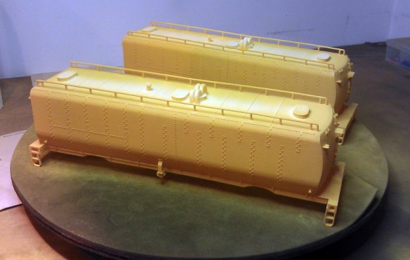
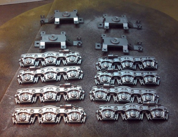
Once all the parts had been cleaned up, in the photo below, they were ready for spraying.

O Scale Tenders Cleaned

The first coat was done with Pollyscale’s (Floquil) UP Armor Yellow paint.  These paints are perfect for spraying 3D printed models made for Shapeways’ Frosted Detail and Frosted Ultra materials as it’s an acrylic paint.  Enamel paints do not dry properly when applied directly to the material and some other brands of acrylic paints don’t spray so well.  Sadly this paint is no longer available.  Straight out of the bottle it was a bit too yellow so for the second coat I added a spot of red into the paint which brought the right amount of orange tint to the color.O Scale Tenders Spay 1

Once dry the yellow areas were masked off and the remainder of the tenders were sprayed with UP Harbour Mist Gray also made by Pollyscale.O Scale Tenders Spay 3

Then, with the mask removed the tenders were ready for decals, well almost.  I had a bit of gray bleed through onto the yellow which had to be brushed out.  This was because a section of the mask had lifted. The trick with spraying is 95% of the time should be spent in preparation, the actual spraying part is really quick.

O Scale Tenders Spay 5

The trucks that come with the Lionel chassis are black so I stripped the parts down, then sprayed them with a basic silver.  Again I used acrylic paint but as all these parts are metal I could have used an enamel paint.

O Scale Tenders Spary 7

I regularly like to do test fits as I go to check things are okay, and below you can see the assembled bodes and chassis with some of the detail parts laid out in front.

O Scale Tenders Spary 6

The yellow in the picture above still looks way too yellow for UP colors but this is a bit of an optical illusion due to the lights I have in my work room.  Also once the red decals are applied it will greatly change the look of the color.

The next stage was to apply the decals.  The lettering and flags where again supplied by Circusdecals, the red lining decals I made myself.  The flag on the sides of Jim Adams is just about the same shape as the flag plate which is provided with the kit.  This plate is very thin and I recommend gluing it to the tender before you apply the decal as decal setting solution will cause the plate to bend if unsupported. Wet slide decals also like flat surfaces to adhere to and these tenders are covered in rivets.  Cutting out the decals as small as you can and then test placing them on the model is a good idea.  If there is still a rivet detail under the decal I recommend carefully cutting that one-off with a sharp craft knife to create a flat surface.

O Scale Tenders Decal 1

I find taking pictures as I go also helps me check what I am doing. In the picture below you can see I had just finished setting the PACIFIC as the side of the tender is still wet.  Looking at the photo I noticed I had the O in UNION rotated by 90°. As the O decal had not been down long I was able to lift it off and rotate it.

O Scale Tenders Decal 2

Once all the decals had dried I sprayed the tender with Testors Dullcote.  This seals the decals to the tender.  The last stage was to glue on the final details such as the tool boxes, ladders, cut levers and brake wheels.  The cut levers and brake wheels were also spare parts ordered from Lionel.  Below is an image taken halfway though this step.  The tender in the background is a HO model.

O Scale Tenders Details 1

Once complete the last thing to do was fit them to the chassis and take some photos.

O Scale Tender Shells Finished 1 O Scale Tender Shells Finished 2 O Scale Tender Shells Finished 3 O Scale Tender Shells Finished 4 O Scale Tender Shells Finished 5 O Scale Tender Shells Finished 6 O Scale Tender Shells Finished 7

And finally all three size tenders together;  N, HO and O.O Scale Tender Shells Finished 8

The O Scale tenders are available in two kits and in both FD and FUD materials from Shapeways.

Jim Adams

Joe Jordan & Jim Adams

The chassis and parts are available from Lionel here.

The decals are available on request from Circusdecals.

The price for Ready-To-Run models are available on request, please contact me through the contact page.

The new owner of the two O Scale tenders has promised some pictures and maybe some video of them running on his layout with big steam and I will share those with you in a later post.  But for now there are more photos of this pair in the gallery.

In next week’s post I will bring you some photos and videos from my visit to the Southampton Model Railway exhibition which was held at Barton Peverill college in Eastleigh.

A Dummy Chassis For an Atlas C-628 or C-630 Shell Part 3

This weekend I was at the Gosport American Model Railroad Group’s running meet and we set up several layouts including most of our N scale modular layout, Solent Summit. This gave me the perfect opportunity to test out my new 3D printed chassis and trucks for my spare Atlas C-628 shells.

The new chassis, as pictured below, has been designed to fit under either a C-628 or C-630 shell made by Atlas.  I now have a few of these spare as the powered chassis have been used for my 3D printed Baldwin DT6-6-2000 and RT-624 (DT6-6-2400) shells.

Alco C-628 Dummy Chassis Render 6

IMAG0606

I also designed the chassis so it could be used as a simple dummy without any working light or electrics. Alternatively it could be used with custom power pickups to supply the original lighting board or maybe a sound decoder.  The power pickups, as shown below, are axle wipers and are made from 1mm wide phosphor bronze strips. They fit into the groves and guides printed into the underside of the trucks.

Alco C-628 Dummy Chassis Render 10

IMAG0603

In addition to the axle wipers a circuit board mount has been 3D printed to hold the original circuit board in the correct place.  This are the white parts you can see in the first two photos above and they fix into the chassis using sprung hooks.  There are holes in the chassis at the hook locations so the parts can be removed by pushing the hooks from the other side with a small screwdriver.

The chassis shown above is the third version I have developed.  For the first I used parts that I had already drawn for another dummy chassis but this put the bolster pin, which is the swivel point of the truck, in the wrong location. This meant as the chassis tried to negotiate corners the trucks swung out too far and fouled on parts of the shell which hang down beside the trucks.

The second version was reconfigured to put the bolster pin in the correct place but although the trucks now rotate correctly the brake pistons, protruding from the cylinders on the side of the trucks, were ever-so-slightly too long. These also fouled on the hanging parts of the shell on tight corners.

With the third version all the issues have been fixed and below is a trio of Alco C-628 locomotives. Two of them are dummys; can you tell which ones?

Alco C-628 Trio - x2 Dummys

The Southern Pacific Loco, No 7102 on the left is a dummy, but what about the other two?

Alco C-628 Monon Pair - x1 Dummy

The Monon locomotive on the right is the dummy. The only visible difference is the colour of the trucks; I painted the dummy trucks with a silver instead of a gray, but with a light weathering on both of them they will become almost identical.

The SP Loco No 7102 is fitted with the circuit board mount and the original circuit board.  Our N Scale layout, Solent Summit, is a DCC (Digital Command Control) layout and as such the track is powered with 16v AC.  This means that both front and rear lights on the dummy locomotive will be on at the same time as shown below.  On a DC (Direct Current) layout the lights will only come on in the direction of travel as normal.  The Monon locomotive behind SP 7102 is fitted with a DCC decoder and is currently set to the forward direction with the lights on.

Alco C-628 SP Dummys With Lights 1 Alco C-628 SP Dummys With Lights 2

For most of the day I only ran the pair of Monon C-628 locomotives with the powered locomotive in front and the dummy behind.  Below is a short video of the pair running through Priddys Yard, past Ted’s Farm and into Solent Summit station.  As you can see the dummy unit has no issues with the curves or drag though the couplings from the train.  The slight hesitation is due to a short elsewhere on the layout, the dummy loco was not phased by the jolt.

In Solent Summit the pair did some switching, and here you can see the dummy being propelled through the crossovers without any issues.

Here is another short video of the train leaving Solent Summit.

This dummy locomotive is ideal for mid train helpers, rear pusher service or for simply adding to your locomotive roster by saving your spare C-628 or C-630 shells.

Alco C-628 Monon Pair - x1 Dummy 2

The dummy chassis kit for the Atlas C-628/C-630 is available here.

The Circuit Board Mount kit is available here.

Alco C-628 Trio - x2 Dummys 2

A small bit of trivia:  The Monon Railroad ran through the state of Indiana before it was incorporated in CSX Railroad.  The Monon line actually passed through a town called Gosport at Gosport Junction so running them at the Gosport American Model Railroad Group’s running meet seemed very appropriate, even if it was in the UK.

In a future post I will share with you some videos of dummy units working as mid train helpers & rear pusher on much longer trains.