Adding N Scale Wheelset Resistors for Circuit Detection

As well as 3D printed models I do a lot with DCC and model railroad wiring.  Recently I have been building computer controlled DCC layout and this adds a whole new level of requirements to the layout such as circuit detection.  In this post I will share with you how I get rolling stock ready for circuit detection on an N Scale DCC layout.

Circuit detection is fundamental to computer control as it tells the computer where trains are on the layout.  It is also useful if you have hidden sidings and you want to know where your trains are.  There are several companies that produce circuit boards for circuit detection and on this layout I have used Digitrax’s BDL168 boards.  The boards work by measuring a resistance across the track; this can be anything from an LED to a DCC chipped locomotive.  So if you have a locomotive in a section connected to a BDL168, even though it’s not moving, the board will detect a resistance and turn on the output for the section.  The output could be connected to a display panel or a computer could pick it up through the Digitrax Loconet system.

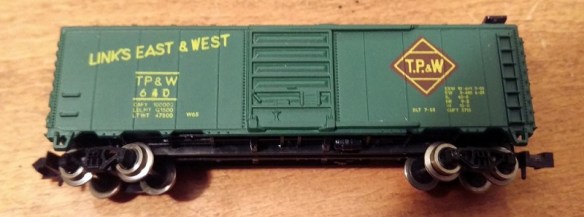
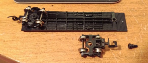
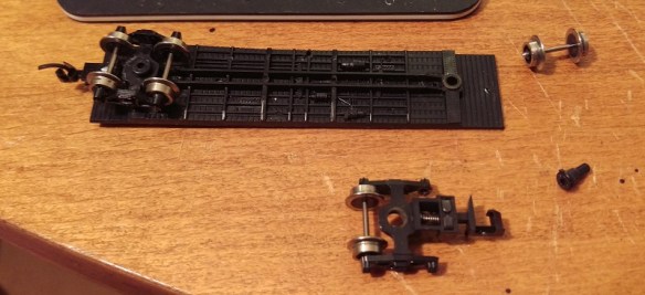
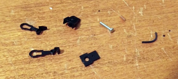
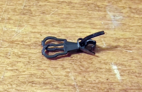
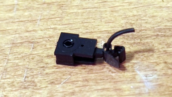
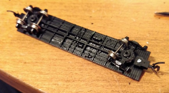
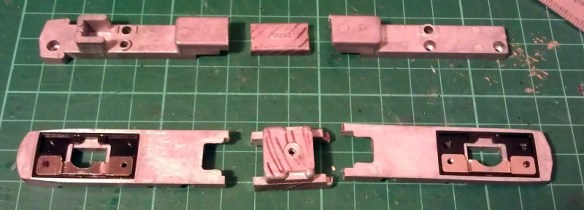
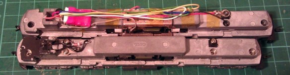
This is fine for locomotives and rolling stock with illumination but what about basic freight cars or wagons?  The computer controlled layout I’m building is a British outline model railway and has a lot of coaches that will all need to be modified so the circuit detection can pick them up.  A lot of the coaches, as shown below, are made by Graham Farish and luckily have metal wheels, obviously plastic wheels sets are no good for circuit detection..

Wheel Set Resistor 1

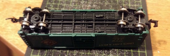
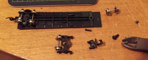
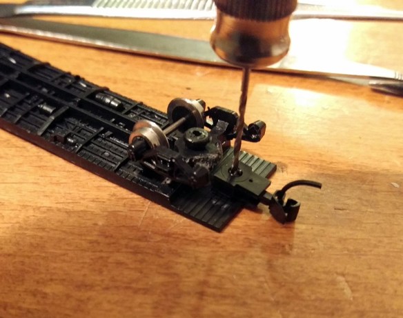
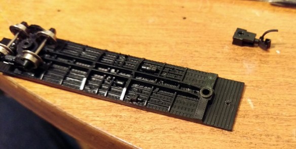
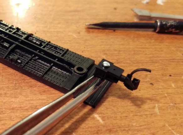
If you do have rolling stock with plastic wheels you can get replacement wheel sets for just about all ready-to-run stock.  Although metal wheels usually run better you don’t have to change all the wheel sets for metal ones, only the ones you intend to modify.  In fact you only need to modify one wheel set per item of rolling stock.  Because of the length of the coach I am going to modify one wheel set in each truck.  If it was a short wagon I would only do one.  Ideally I would like to modify the two outer wheel sets but as the axle is so close to the coupling box there would be no room.

Wheel Set Resistor 2

Adding lighting to the coach would be one way of creating a resistance across the coach but by far the simplest way is to add a resistor to a wheel set.

Wheel Set Resistor 13

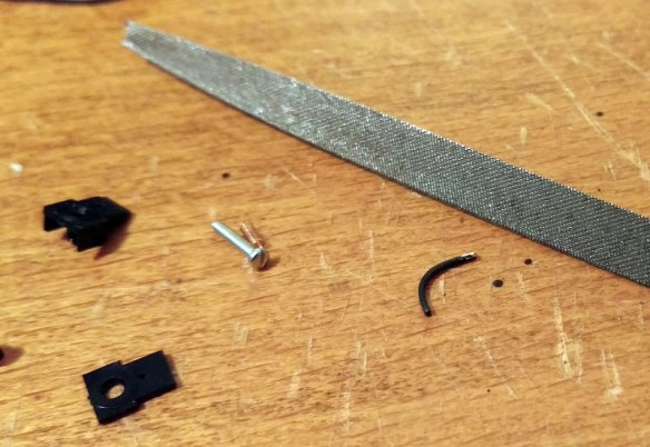
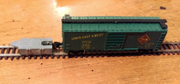
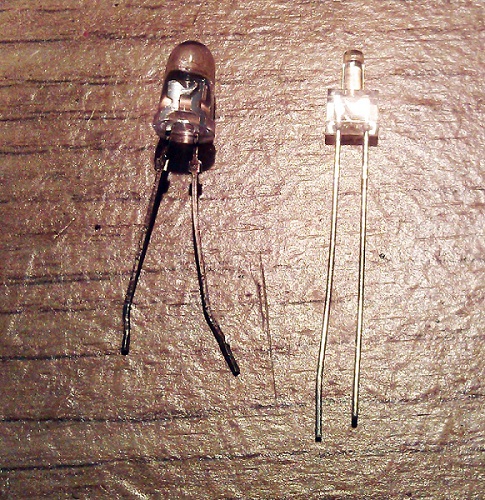
As you can see from the images above with N Scale, and OO/HO, a standard resistor is a bit big and would be very impractical.

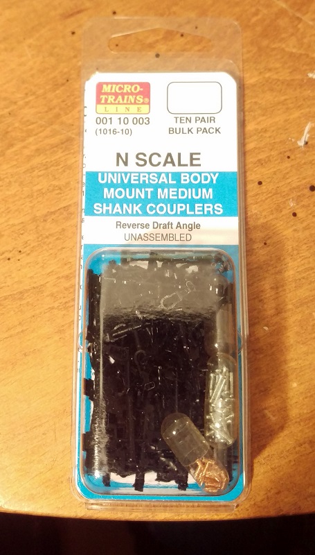
To overcome this, tiny resistors called ‘Chip Resistors’ are available, and are also very cheap to buy.

The best size of resistor for this job is a 10K Ohm.  The Ohm rating is the measurement of resistance and it is important to get this correct as the wrong resistor may cause heat which might warm up the wheel set and melt your train.  The chip resistors are usually supplied in strips as shown below.

Wheel Set Resistor 3

Close up you can see the tiny chip resistor, each one is in a pocket in the strip and covered by plastic film.

Wheel Set Resistor 4

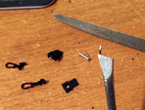
Below is a comparison of the strip with an N Scale 3 axle tender truck.

Wheel Set Resistor 5

Once the chip resistor is popped out of the strip you can see just how small it is.

Wheel Set Resistor 6

And immediately you can see the advantage over the traditional resistor.

Wheel Set Resistor 7

The next issue is how to fix the resistor to the wheel set.  If you attempt to solder it on I guarantee it will go wrong.  The heat from the iron will heat up the wheel set and melt the plastic spacer between the wheel and the axle.  This will cause the wheel to become out of line and wobbly.  It may even cause a direct short across the wheel set.  The other option is to glue the chip into place.  This also has a few problems because if you get glue between the metal contact of the chip and the wheel or axle, the chip will not be able to conduct electricity.  To overcome this I have used Wire Glue made by Anders Products.

Wheel Set Resistor 8 Wheel Set Resistor 9

This is glue that has been designed so once it sets it will conduct electricity.

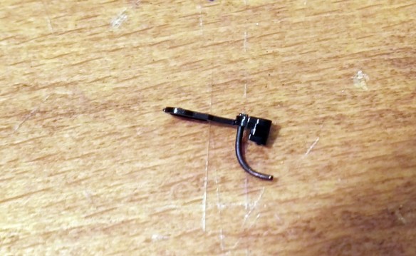
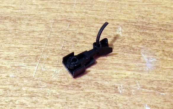
Unlike superglue or CA the wire glue needs time to dry, normally overnight, and that means it needs to be left where it won’t be knocked or moved.  Sitting one of those tiny chips on an axle that rotates is not very practical so I pop out the wheel sets and gently hold one of the wheels so the set can’t roll over.  Make sure what you are using to clamp the wheel set is not too strong as you don’t what to damage the wheel.  I would also recommend checking the wheel centers are correct before gluing the chip in as you won’t be able to move it once the glue has set.

Wheel Set Resistor 10

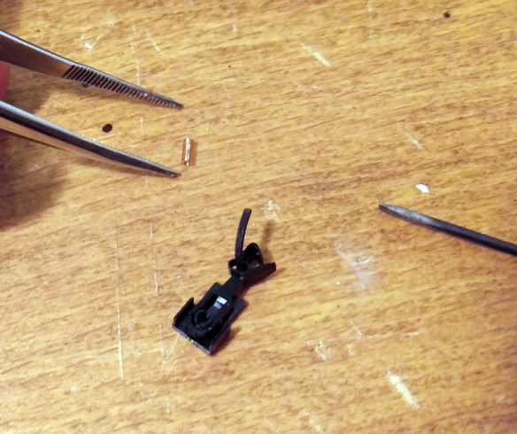
Once you are ready, and have stirred the wire glue, use a tooth pick to put a tiny amount on the axle and the inner face of wheel making sure you don’t bridge the plastic spacer with the glue.  Then using a pair of tweezers position the chip so one end touches the axle and the other touches the inside of the wheel.Wheel Set Resistor 11Once it has dried a little I put a bit more glue over the top to ensure everything makes contact.

Wheel Set Resistor 12

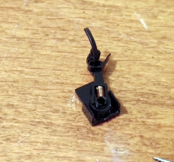
If, like this particular wheel set, both wheels have a plastic spacer you will also need to bridge the other side.  I have done this simply by spreading some of the glue across the spacer from the wheel to the axle.

Once dry you can check the resistance across the wheel set with a multi-meter.

This glue generates a fair amount of resistance itself so it would not be good for main DCC wires etc but for this purpose it does the job nicely.  I also don’t think it’s as strong as most glues so to make sure the chip won’t come off you could also put some superglue or CA over the top once you know it works okay.

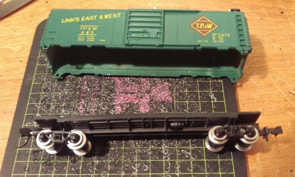
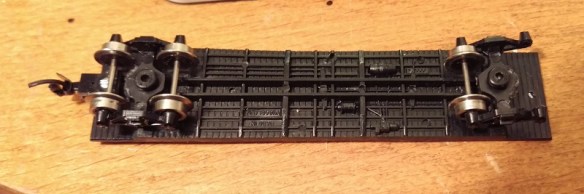
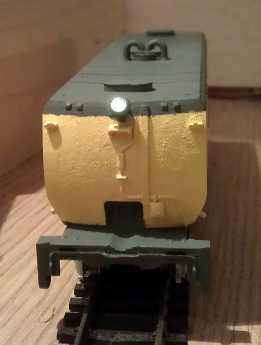
Then it is a simple matter of fitting the wheel set back into the truck and the coach is ready for use on any layout and will trigger track detection on layouts with circuit detection.

Fitting Micro-Trains Body Mount Couplers To Older N Scale Freight Cars

With the NMRA (BR) Convention coming up this weekend I decided that some of my running stock needed some attention before the show.  A lot of my older rolling stock still has the Rapido style couplers and some of the newer stuff has Atlas’ Accumate couplers.  My preference for couplers has always been to use Micro-Trains as I have found them to be the most reliable.  In this post I will share with you how I convert older rolling stock to MT couplers in a fairly cheap way.

The box car below is a typical 40 foot car with Rapido couplers fixed to the trucks.  By far the simplest way to convert this car would be to buy a set of MT trucks, which come with couplers pre-mounted, to replace the originals.  However this can become very expensive if you have lots of cars to convert.

Micro-Trains Body Mount Coupler Fitting 1

Another slightly cheaper alternative is to buy an MT conversion kit that will replace the coupler in the truck.  These can be a bit tricky to fit but work very well and you get to keep the original wheels.  The car I’m converting has metal wheels which are clean and in good order, making it a good runner.

For me the cheapest option is to use body mounted couplers.  Again this means you get to keep the existing wheels and trucks but the existing couplers are removed totally.  The new couplings are fixed to the underside of the car chassis.  This is actually more prototypical and transfers the weight of the train through the chassis, bypassing the trucks and bolster pins.

The MT body mount couplers are available in pairs or in bulk packs as shown below which is certainly the cheapest way to buy them.

Micro-Trains Body Mount Coupler Fitting 2

To make the change you will need a few basic modeling tools as shown below.  I use a small watchmaker’s screwdriver, flat file, craft knife, needle nose tweezers, flat end tweezers, MT gauge, pin vice with a drill (from the MT Tap & Drill Set – 00-90), side cutters & pliers.

Micro-Trains Body Mount Coupler Fitting 3

To start you should check that the car is in good running order.  You can see I have already changed the left hand coupler.

Micro-Trains Body Mount Coupler Fitting 4

The body should simply pull off the chassis and can be put to one side.

Micro-Trains Body Mount Coupler Fitting 5

While the body is off it’s a good chance to check that the weight inside the car is properly secured; it’s normal for this to be rusty as it’s simply a strip of unprotected steel.  If the weight is loose simply glue it back into place before continuing.

Micro-Trains Body Mount Coupler Fitting 6

Next remove the truck by pulling out the bolster pin.  You can do this either with the pliers or by simply pulling on the truck.  Make sure the bolster pin does not fly off.

Micro-Trains Body Mount Coupler Fitting 7

With the truck removed the front wheel set can be taken out by gently pulling the truck side frames apart.

Micro-Trains Body Mount Coupler Fitting 8

Then using the side cutters snip off the coupler leaving enough material surrounding the bolster pin hole.  You won’t be able to do this in one snip as the truck side frames will be in the way.  I find five snips normally does the trick.  Once finished the top of the truck needs to be flush otherwise it may hit the new coupler.  If the area where you sniped is a bit rough you can use the file to smooth it out.

Micro-Trains Body Mount Coupler Fitting 9

The truck can then be loosely re-fitted, there is no need to push the bolster pin in hard as it will be removed again shortly.

Micro-Trains Body Mount Coupler Fitting 10

The bulk pack of couplers contains lots of parts but to assemble one coupler you need the five laid out below.  They are the coupler hook and catch plate, coupler box and top plus a spacer, screw, spring and drop pin.

Micro-Trains Body Mount Coupler Fitting 11

Using the craft knife remove the coupler hook and catch plate as well as the coupler box and top from the sprues.  The spacer is the flat part on the right and may be required later so put it to one side.

Micro-Trains Body Mount Coupler Fitting 12

With the parts removed there’s one small thing I like to do before assembling the coupler and that’s to use the file to deburr the top of the drop pin.  This simply makes it fit easily without too much force which can break the coupling hook.  The end that fits into the coupler hook is the longer leg.

Micro-Trains Body Mount Coupler Fitting 13

I tend to hold the pin in the tweezers or pliers and run the file on four sides of the pin at 45°.

Micro-Trains Body Mount Coupler Fitting 14

With the pin still in the tweezers or pliers push the filed end into the small hole in the coupling hook.  The pin should be at an angle which is parallel to the side of the hook.  The pin only needs to go through the hook so the end is just poking out of the top.

Micro-Trains Body Mount Coupler Fitting 15

With the pin fitted slide the coupler catch plate over the pin.

Micro-Trains Body Mount Coupler Fitting 16

With the coupler box on its back place the assembled parts over the tube in the box.

Micro-Trains Body Mount Coupler Fitting 17

The next part is the most tricky.  There are several ways of doing this but for me I like to use a pair of needle nose tweezers and a watchmaker’s screwdriver.  The risk is that the spring will ping off and, given how small these are, you usually can never find it.  Luckily MT provide several spares in the kit.  I find it’s best to get the spring close to the coupler and almost in the same orientation.  Then carefully compress the spring with the tweezers and place it over the slot between the coupler box tube and parts.  Using the screwdriver push the spring down into place and release the tweezers.

Micro-Trains Body Mount Coupler Fitting 18

Once in, the spring will stay there, but the assembly is very delicate so don’t knock it or the spring may ping out.

Micro-Trains Body Mount Coupler Fitting 19

Using the tweezers place the box lid on to the box and press down with your finger.  It should clip into place.  The lid only fits on one way round and the underside has groves to fit onto the box.

Micro-Trains Body Mount Coupler Fitting 20

Once the lid is clipped on the coupling is fairly robust and can be moved about.  Check that the coupling moves in the box and bounces back to the same central position.

Now it is time to fit it to the car chassis.  The particular set I am using are medium length, for a 40 foot box car. A short length might have been better but they will work just as well.

Place the coupling on the underside of the chassis and pass the drill through the box tube.  Once the coupling is as far back as you want it, ensure the truck can rotate and the coupling is centered, and use the drill to mark the chassis.

Micro-Trains Body Mount Coupler Fitting 21

Then remove the coupling and truck so you can easily drill through the chassis.  Depending on the make of the car the distance from the edge will vary, but I tend to find the hole needs to be halfway between the third and forth plank counting from the edge.  As this car has a plastic chassis the metal screw will cut its own thread.  However if the chassis is metal you may want to use the tap that came with the MT tap and drill set to cut a thread in the chassis.

Micro-Trains Body Mount Coupler Fitting 22

Next push the screw into the coupler box hole from the underside.

Micro-Trains Body Mount Coupler Fitting 23

I find pushing the screw all the way though and holding it with the needle nose tweezers helps keep the screw straight when you start to tighten it up.

Micro-Trains Body Mount Coupler Fitting 24

Once the screw is started you can let go with the tweezers and tighten it up.  Make sure the coupler is square before you fully tighten it. You will notice that the screw is now sticking through the floor of the chassis.  This is not a problem as it will be inside the box car but if your car has a veranda, such as you get on a caboose, or is simply a flat car, you will want to shorten the screw with the side cutters first. Note: you will also need to use a big set of side cutters for this as you may break a modeling pair.

Micro-Trains Body Mount Coupler Fitting 25

The truck can now be installed.  If the truck can rotate freely push the bolster pin in all the way and refit the wheel set.

Micro-Trains Body Mount Coupler Fitting 26

The last thing to do is check the height of the coupler.  Using an MT gauge as shown below this is very easy to do.

Micro-Trains Body Mount Coupler Fitting 27

Simply clip the gauge to the track, shutting off the power first, and test the new coupling with it.  Should the coupling be too high simply unscrew the coupling and add the spacer that we put to one side earlier. This will lower the coupling.  In the unlikely event that the coupling is too low then remove the trucks and add a washer to each; this will raise the whole box car correcting the coupling height.

Micro-Trains Body Mount Coupler Fitting 28

The box car is now ready for service.

As I said at the beginning the NMRA (BR) Convention is this weekend at Derby, England and I will be there along with my fellow modelers running the N Scale modular layout ‘Solent Summit’, and my new modules will be there.  The convention is open to the public on Sunday and it would be great to meet anyone who is coming along. If you can’t make it I will be giving a full report here in the coming weeks.  This week I will leave you with a taster from my new modules, below is a video of a ‘short’ train crossing the Warsash River on the Warsash Wye trestle.

Drawing an Alco C-855 for N Scale Part 4

This week I’ve been working on the Alco C-855 project and I’ve assembled the chassis using the 3D printed metal chassis extenders.  In this post I will share with you how I did it.

You can read about the design for the metal and plastic parts for the extenders in my earlier post which you can find here.  The metal chassis extenders are required because the donor chassis, taken from a Con-Cor model of a GE U50, is not long enough for the huge Alco C-855.  The chassis extenders, pictured below, have been 3D printed in stainless steel.

C-855 Chassis Extenders 1

To start with the donor chassis is stripped down so only the two main metal parts are left.  It is best to remove any moving parts when cutting the chassis as metal filings can get into the gears and bearings causing damage at a later date.

C-855 Chassis Build 1

The two parts pictured above, along with the new sections, are ready to be marked for cutting.  I like to use a permanent marker to shade in the areas that need to be cut, as you can see below.

C-855 Chassis Build 2

Once I was happy with the marked areas I used a hack saw to cut the unwanted chassis sections out.  I will be providing instructions when these parts are released for sale with dimensions for where to cut.  Once removed the chassis sections looked like this.

C-855 Chassis Build 3

To fit the parts together I used a superglue but an epoxy will work just as well.  Because the parts are designed to fit together along a step it is fairly easy to get them in the right place. However it is still possible to fit them together at a slight angle so I recommend using straight edges as guides.  I used the back of a metal ruler for a base plate and my metal square as a side.

C-855 Chassis Build 9

I started with the top section and, as this is a test piece, I only glued one side first.  In the photo below you can clearly see the difference in size between the new section and the part that was cut out.

C-855 Chassis Build 7

Before I glued the other side of the top section together I wanted to check things were going right so I test fitted in the lower section of the chassis with the motor. As you can see from the photo below there was a slight problem.

C-855 Chassis Build 5

The motor appeared to be sitting too high in the lower part which looked to be preventing the top section from coming down squarely.  However after further inspection the motor was found to be in the correct place but the top section was a bit too thick.  This was caused partly by the rough surface on the unpolished stainless steel, and also because the superglue added a layer of thickness between the parts.  This was easily resolved by grinding down the underside of the chassis extender.  I used a sanding stone in a Dremel-style tool and removed some of the thickness as you can see below.  Interestingly the stainless steel is much harder than the metal used for the original chassis and it took a bit if working The metal got incredibly hot but the superglue joint held up with no problems.

C-855 Chassis Build 8

With the extension part modified the motor section now fitted properly, so I glued the other end on using the same metal square and ruler.

C-855 Chassis Build 10

The gap you can see in the picture below at the top of the right hand joint is because I slightly over-cut the chassis. However that is not problem as the step below is the part which correctly positions the extension.  I later filled this gap with more superglue.  I used the Gel Control Superglue made by Loctite which is perfect for jobs like this as you get a bit of working time before it dries and, being a gel, it will not run.

C-855 Chassis Build 11

Before moving on I also did some squareness checks as you can see below..

C-855 Chassis Build 12
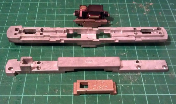
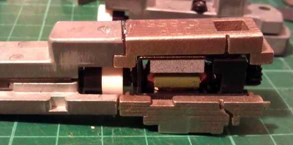
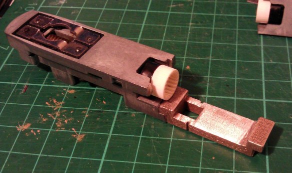
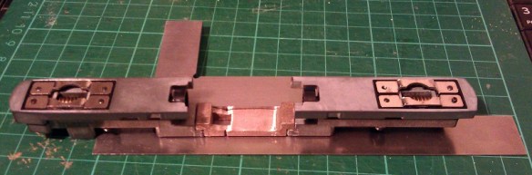
Now the top section was complete I could position and glue in the motor section.  You may have noticed I left the top and bottom sections of the chassis bolted together throughout most of this.  I did this to help ensure everything was in the correct place, particularly when it came to fitting the motor section.  As it happened I did cut the lower front chassis section a bit short and if I had glued the whole bottom section together tightly it would have been too short.  However as the chassis parts were bolted it all worked out well and below is the chassis glued together.

C-855 Chassis Build 13

Next I refitted the trucks and other internal parts ensuring there werre no metal fillings in any of the moving parts. I lubricated the motor, gears and drive shaft bearings and also put a strip of Kapton tape over the top motor brush connector.  It was ever-so-slightly touching the metal of the chassis extender and, as I proved in my prevision post, these stainless steel parts conduct electricity very well.  If this locomotive was going to be run as a DC locomotive this would be great but it will be DCC so I needed to isolate the motor.

Although the chassis extenders are great conductors the fact that I used superglue for the joints helped to form a perfect electrical barrier, so to ensure I get the benefit of all the power pickups, I bridged the chassis extenders using the original bolts, as you can see below.

C-855 Chassis Build 14

The two nearside bolts are in plastic sleeves so they don’t touch the top section of the chassis but conduct power from the bottom section.  The bottom section is connected to the right hand rail and the top is connected to the left.  To complete the test I also fitted a DCC decoder and the lighting and function wires are simply taped to the chassis for later use.

C-855 Chassis Build 15

The longer mechanism had no problem navigating some S bends and small radius turnouts on my switching layout.  I will also do a few tests on a bigger layout this week with a train in tow to see how it performs and I will share a video of that with you.

Below you can see some side by side comparisons between an original Con-Cor U50 chassis and my extended C-855 one.  The original chassis weighs 170g (5.99 ounces) and the extended one weighs 186g (6.56 ounces).  The C-855 did have 500 more horsepower than the U50 so this extra weight will help with traction.

C-855 Chassis Build 16 C-855 Chassis Build 17

I have now made some modifications to the chassis extension 3D model drawing to fix the issue I had with the first build. I will do one more test print before I make them available,, just to confirm that everything will fit together without modification.

The next step for the C-855 is to finish the 3D model for the shell and brass Additions.  Once I get them drawn up and ordered from the printer and etcher I will share them with you.

3D Printing in Extreme High Definition for All – from Shapeways

In January of this year I shared with you some 3D printed locomotive shells that had been printed in Extreme High Definition by a firm in London, England called Impossible Creations Ltd.  You can find the post here.  Since then other companies have been branching out into higher definition printing as the demand for better quality prints has been rising.  Shapeways have now entered this market with their new Frosted Extreme Detail plastics.

Shapeways-fxd-email-hero-625x468

The image above is from Shapeways’ launch blog post on their website. (That is not my finger.)

Frosted Extreme Detail or FXD is basically the same as the Extreme High Definition I have already used from Impossible Creations. It is printed in the same type of printer made by 3D Systems.  The only difference is the material. Impossible Creations use VisiJet M3 Procast which is a blue material, originally designed to be used in a lost cast process to manufacture jewelry from 3D printed models.  Shapeways use VisiJet M3 Crystal which is the translucent material we all know as Frosted Detail and Frosted Ultra Detail.

FXD has a much smaller layer thickness than FD or FUD, the thickness is measured in Microns and the thinner the layer the higher the definition or resolution.

FD prints at 32 Microns

FUD prints at 29 Micros

FXD prints at 16 Micros

Shapeways have set their parameters for printing in FXD to the same level as FUD; with the exception of the boundary box.  The boundary box is the overall size of model which you can print and they have done this for a very simple reason; time.  They have set the size to 50mm by 50mm by 200mm,  200mm being the hight.  If this space is full at a 16 micron layer thickness it will take 48 hours to print.  If they had set it to 200mm by 200mm by 200mm it would take 192 hours or 8 days!  Keeping the time down keeps this material cost effective.

Fortunately for a lot of my models this is not to much of an issue as most will fit, well maybe not the O Scale stuff!  The majority of my models have already been switched over so they are now available in both FUD & FXD.  One of the nice things about this, apart from the better quality, is the price.  Although the FXD costs more per cubic centimeter the base price is still the same.  Shapeways are charging a $5 fixed fee per model, as they do with FUD, plus the material costs.  So small models like my N Scale Three Chime Horns, as pictured below, are only $0.50 more expensive for a much higher quality in FXD.

Horns 3

Larger models like locomotive shells will end up costing a bit more.  For example my N Scale Baldwin RT-624, as pictured below, in FUD costs $55.  In FXD it costs $80.22. That may sound like quite a hike in price but when compared to other companies offering the same lelvel of high quality printing the price rise is actually minimal. (Please note the actual price varies depending on your country, taxes and currency exchange rate).

Baldwin RT-624 Render 3

A few of my models are still being converted, such as the big EMD DD35 so they are not available in FXD just yet. But it won’t be long.  If there’s a model that you would like in FXD and it is not yet available please contact me through the Contact Page or drop me an email at jamestrainparts@yahoo.co.uk and I can either make it available or let you know when it will be.

One downside to this exciting news is that Shapeways will no longer be offering models in their FD material.  This is because FD requires a lot more support material, which is as expensive as the main material.   So in order to make it cost effective they need to raise the price; however this will make it the same price as FUD which is a higher resolution material and therefore FD will become redundant.

This is a shame because FD was beneficial to large-scale models such as my O Scale UP Tender.  At such a large-scale the cost difference between FD and FUD was a lot. These are definitely too big for FXD.  However Shapeways will be continuing to offer FD untill the 29th of April 2015.  I know that is not long but you can still order the FD O Scale tenders untill then.

Another bit of good news, Shapeways are offering 10% off all orders untill the 23rd of April 2015 with the discount code ‘THANKYOU10‘.

All of my new models will also be available in FXD including the big Alco C-855 which will be making an appearance soon.  I will also be making my own orders in the FXD and I will be sharing them with you, that’s if you don’t beat me to it using the discount code.

Adding Lights to a HO Scale Union Pacific Water Tender Part 3

In last week’s post I shared with you my work on adding working headlights to a set of my HO UP tenders; you can find the post here.  For this week’s post I will share with you how I completed the project.

Having already constructed the power pickup assemblys and installed the DCC decoders the last thing to do was to install the headlights.  For this I used headlights from a Bachmann 2-8-4 Berkshire locomotive. These, when in stock, can be obtained from Bachmann as spare parts.  They come as part of the smoke box door assembly as shown below.

HO Tender Headight 1

The headlamp is an injection molded part with a clear plastic lens that fills the headlight and runs out the back as shown below.   The lens tail has been painted black to prevent light from spilling out sideways.  With the 2-8-4 locomotive the light is inside the boiler and travels through the lens tail to the headlamp.  I intend to do the same thing.

HO Tender Headight 2

First I need to spray the plastic part with UP Harbour Mist Gray; I removed the lens to do this.HO Tender Headight 3

As I mentioned in last week’s post; I didn’t want to install the headlights untill all painting and decal work was complete.  This has now been done and the tenders are ready for their headlights.  The lamp assembly consists of the parts as shown below; the lighthouse LED with its resistor, a joiner and the headlight.  For the joiner I have used a section of plastic insulation cut from a mains electrical cable.  The inside diameter is the same as the LED and headlight lens tail so they all push fit together well.  With the parts assembled I painted the visible bits of the LED with black paint to minimise and light from inside the tender.

HO Tender Headight 4

A hole in the shell needs to be drilled just above the headlight support bracket for the lens tail to stick though; then the headlight can be glued in place.

HO Tender Headight 5 HO Tender Headight 6

Fitting the LED & joiner to the back of the lens tail inside the tender was a bit awkward to do as my hand fills the avalable space.  This also made it impossible to photograph.  However I achieved it by powering up the LED, which not only checked to make sure it was pointing straight through the joiner but also helped me see what I was doing.  Once it was aligned I pushed the joiner over the lens tail and glued the whole assembly to the roof of the tender.  Then the tenders could be fitted to the chassis and a test of the headlights could be done.

HO Tender Headight 7

Both headlights are bright but with a warm glow.  On DCC power they could be turned on and off with the F1 function.  And with a flick of the switch on the underside of the chassis they become DC powered and function like ordinary directional headlights.

The final stage was to add the rest of the details such as the roof top tool boxes and ladders.

HO Tender Headight 8

These tenders also need coupling to be completed and then they will be ready for service.

The Backmann headlights worked well but I would prefer to develop my own for use on other projects.  Having the lens carry the light from inside the tender seems to be a good idea for this so I will experiment with 3D printing the headlight and running a fiber optic cable from the back into the tender for the next set.  I will share this with you when when its done.

Adding Lights to a HO Scale Union Pacific Water Tender Part 2

Two weeks ago I shared with you the first part of this post about adding working lights to some of my HO Scale Union Pacific excursion train water tenders.  You can find the post here.  In this week’s post I will share with you the next step.

At the end of the previous post I had gotten as far as adding the power pickups to the 3D printed trucks and installing the DCC decoder as you can see in the image below.

HO UP Tender Power Pickup 17

The original idea was to simply hook the white and blue wires up to an LED which was mounted inside the tender shell.  Below you can see the chassis with the LED fitted and working.  I have also added some weight to the chassis which greatly improves the power pickup.  The weight is off-center to avoid the baffle in the center of the tender shell.

HO UP Tender Chassis Switch 7

However upon testing the system I discovered a small problem.  Because the DCC decoder I had selected is a function only decoder, that is to say it has no motor controls, it works well when run on a DCC layout but will not function properly on a DC layout.  This is because a function only decoder doesn’t recognise direction.  A regular DCC decoder will recognise forwards and backwards, switching on the relevant wires to turn on the correct lights.  A function only decoder will simply respond to function key commands.  In the case of the Digitrax TL1 that I have used; F1 will turn the white wire on and off.  When the tender is running on a DCC layout the operator can consist the tender with the locomotive, then when they push the F1 button the tender headlight will come on as required.  But under DC control the headlight will only continue to do whatever the last command was under DCC control.  For example if the light was lit when running on DCC, the light will remain lit in DC irrelevant of direction and cannot be turned off.

As these two tenders are wanted for both DC and DCC operation I will need to come up with another solution.  One option would be to replace the function only decoder with a full motor decoder.  That way it would respond to directional control in both DC and DCC but there would still be the risk of it being removed from the DCC layout with the light off, then it would not work on the DC layout.  Also full motor decoders are more expensive.  A simpler option that I have decided to use is to add a switch to the underside of the tender chassis which will allow the operator to switch the tender from DCC to DC control.  That way the function decoders that have already be purchased will not be wasted.

The type of switch required is a double pole double throw toggle switch.  Double pole means that it can switch two separate wires at the same time; in this case positive and negative.  Double throw means rather than simply on and off it switches each pole from one input to another; in this case DCC power to DC power.

As I described in part one of this post each truck picks up power from a different rail.  Irrelevant to whether it is a DCC or DC layout, one rail is treated as positive and one as negative.  At this point the two power wires need to be divided so that power goes to the DCC decoder and to one side of the switch.  The output from the DCC decoder will then go to the other side of the switch.  From the middle of the switch will come the two wires that feed the LED.  When the switch is set to the DCC side the system will operate as it did before, responding to the F1 command on a DCC system.  With the switch set to the DC side the power will bypass the DCC decoder and go directly into the LED.  Because and LED is a diode, which means power can only pass through in one direction, the light will only come on when the train is moving in the direction the light is facing.

To find the right DPDT toggle switch I had to look at the available space on the chassis.  Although there is a lot of room inside the tender itself, there is not a lot under the chassis and I did not want something huge sticking out that looked unsightly or might foul things like turnouts or crossings.  A standard DPDT toggle switche would be simply too big, as would a sub miniature one; but an ultra miniature one would work well.  Below is an ultra miniature switch next to a miniature one.

DPDT Swiches

The switch will be mounted to one side near the center of the chassis.  That way there is no chance of it interfering with the swing of the trucks.

HO UP Tender Chassis Switch 1

Although this switch is very small the lever that projects out is still too long so I cut about two-thirds of this off with a disc cutting tool and filed the edges to remove any sharp bits. It is now fairly inconspicuous under the chassis.

HO UP Tender Chassis Switch 2

A small corner of the air tank also had to be cut off to allow the toggle switch nut to be fitted but this will not be visible when the tender is on the track.  The switch will also be painted gray to match the chassis helping it blend in.

HO UP Tender Chassis Switch 8

Next the switch needs to be wired up.  The red and black wires from the trucks go to the two terminals on the far side.  The DCC decoder is then also connected to the same terminals.  This is where the power is split.  The output from the DCC decoder, the white and blue wires, are connected to the near side terminals.  With DCC decoders the blue wire is the common function wire which is positive. Therefore it needs to be connected to the switch on the same side or pole as the red wire.  If the light was powered by a regular bulb this would not make a difference but because LEDs are diodes the polarity of the wires is important.

HO UP Tender Chassis Switch 3

Next the LED wires are connected to the two center terminals as shown below.

HO UP Tender Chassis Switch 4

Often DPDT toggle switches have three positions, the middle being off.  This can be useful as it ensures there is no chance of a short as the switch is thrown. However the ultra miniature switches only have two positions but as the tender needs to be removed from the track to throw the switch this is not a problem.

The LED I am using is a 2mm lighthouse style with a warm white color.  Regular white LEDs are often too bright and give a very cold light.  I should also point out that it is necessary to use a resistor with every LED otherwise they will draw too much power and blow immediately.  Below is a comparison between an ordinary 5mm LED and the 2mm lighthouse LED.

HO UP Tender Chassis Switch LED

The light these warm white LEDs give off is perfect for recreating locomotive headlights as you can see from the images below.  For these photos the headlight has not been properly secured so it is pointing up a bit.  I need to finish the shell and add all the decals before I can fix the headlight on properly.

HO UP Tender Chassis Switch 6

Taking photographs in the dark is not the easiest thing to do but below is a shot of the tender in low light, as you can see the headlight gives a nice beam.

HO UP Tender Chassis Switch 5

In next week’s post I will share with you the final stage of fitting the LED into the shell.  I will have also finished the shells, completing the tenders.