The London 3D Print Show 2015

Last weekend saw London host the 2015 3D Print Show and as this is something very important to what I am doing I went along to see what new products are coming out and to have good look at the new range of home or desktop 3D printers.

As expected with such a show there were all types of stands from manufactures of 3D printers to suppliers of 3D printing parts and services.  They even had a 3D printed food bar!

In particular I was interested in seeing how the desktop 3D printers had improved since I first started getting in involved.  I wanted to know how the quality of the finished prints came out and if they could be used succesfully for my 3D models.  I had a close look at the big name manufacturers as well as a lot of the new machinery that is coming from startup companies, several of which have been funded by Kickstarter programs.  For the most part the desktop machines all work in the same way with plastic filament being heated and laid down by a print head. The limiting factor with this technology used to be the layer thickness, the thicker the layer the more lines are visible on the print.  But now as the manufactures have found ways to reduce this thickness, the size of the print head nozzle is becoming more of issue.  If you can imagine a very small detail on a part, the quality that is attainable is dependant on the width of the material coming out of the nozzle.  Out of all the ‘traditional’ 3D print machines the Ultimaker 2 printers seemed to have the smallest print head nozzles and were giving a nice product but sadly for any of my 3D models the layering effect was still too intrusive.

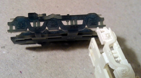
The next development to the machines that has made a noticeable improvement was a change in the way the motors and drive mechanisms that move the print head worked.  Traditionally there is a motor for the X and Y (both horizontal) movements. Each drive a rubber belt which move the print head.  The motors are usually very accurate steeping motors which gives the accuracy when moving the print head but there is still ‘wobble’ generated by the movement and the faster the printer is working the more ‘wobble’  you get.  The improved machines, as pictured below, still use motors and belts but the system is very different.  There are three motors that each move a belt vertically. Attached to each belt is a pair of fixed length rods.  The print head sits at the convergence of the three pairs of rods.  As each motor adjusts the height of its belt the head moves over the print. If all three motors work together the height is adjusted. This new style of mechanism is clearly smoother than the traditional X and Y system and gave a better finish.

3D Print Show 2015 - 1

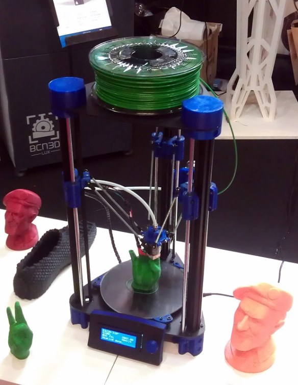
However once again the layering effect was still not good enough to be acceptable for my 3D models.

There was only one 3D desktop printer that I feel comes close the level of quality required for my 3D models and that was the Form 1 built by Formlabs.  This machine is totally different to the others.  It has a tray that is filled with a plastic liquid.  The build plate is lowered into this tray and a laser fires up through the tray and solidifies the parts that you want to the underside of the build plate.  As the machine is working the build plate is raised and the model is pulled out of the liquid.  Because this system has far less moving parts to add ‘wobble’ into the finished print, in my opinion, it gives the best finish out of all the desktop printers.  And I must say for some of my models it would work well.

Formlabs Form +1

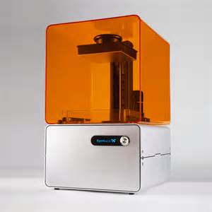
The one issue all of these printers had in common was the locations of the support material.  This is the structure that supports overhanging parts as they can’t be printed in mid-air.  These need to be broken off and this always leaves a small mark, similar to an injection mold mark.  Both Ultimaker and Formlabs seem to have got this down to a minimum but I could still see on the models they had printed at the show where they needed to be touched up.

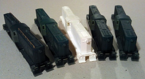
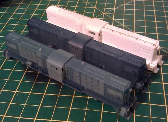
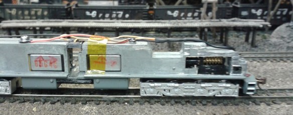
So the question is would one of these replace the need to get my models printed by Shapeways?  The answer is not yet.  The other issue is, as the technology for the desktop printers has improved, so has the technology for the commercial printers.  You may recall from a few weeks ago I posted about Shapeways new material FXD (Frosted Extreme Detail), you can read the post here.  I have now had parts and locomotive shells printed in this new material and I am very impressed.  Below is a comparison between two N Scale EMD DD35 shells.  The one on the left is printed in FUD (Frosted Ultra Detail) and the right in the new FXD, these pictires were all taken by Mike Musick. Normally I reduce the size of image files for my posts but I have left these as large images so if you click on them you can see the detail.

Mike Musick DD35 In FXD 1
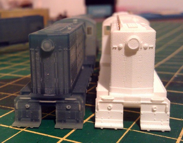
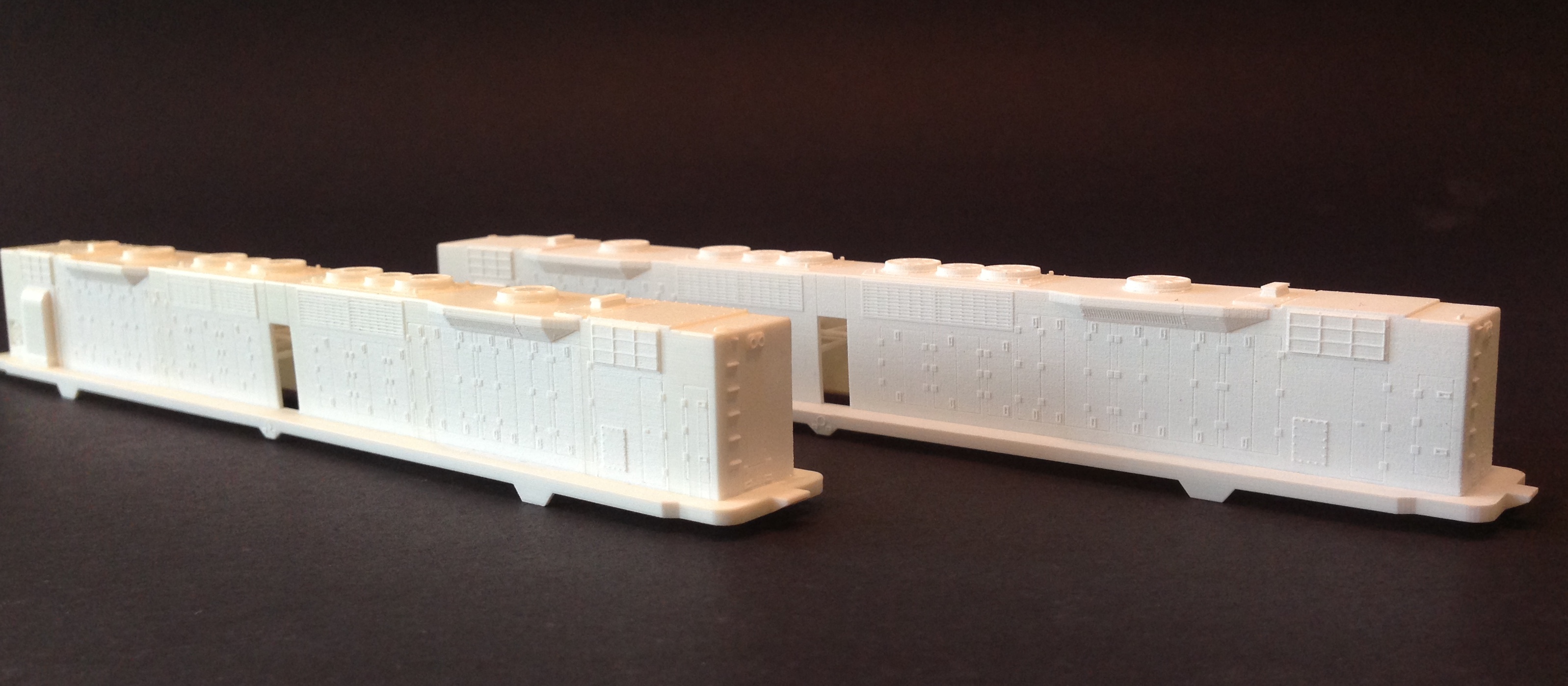
In the photo below you can see the shadow effect under the headlight at the top of the model on the left.  This has not happened with the FXD model.

Mike Musick DD35 In FXD 2 Mike Musick DD35 In FXD 3
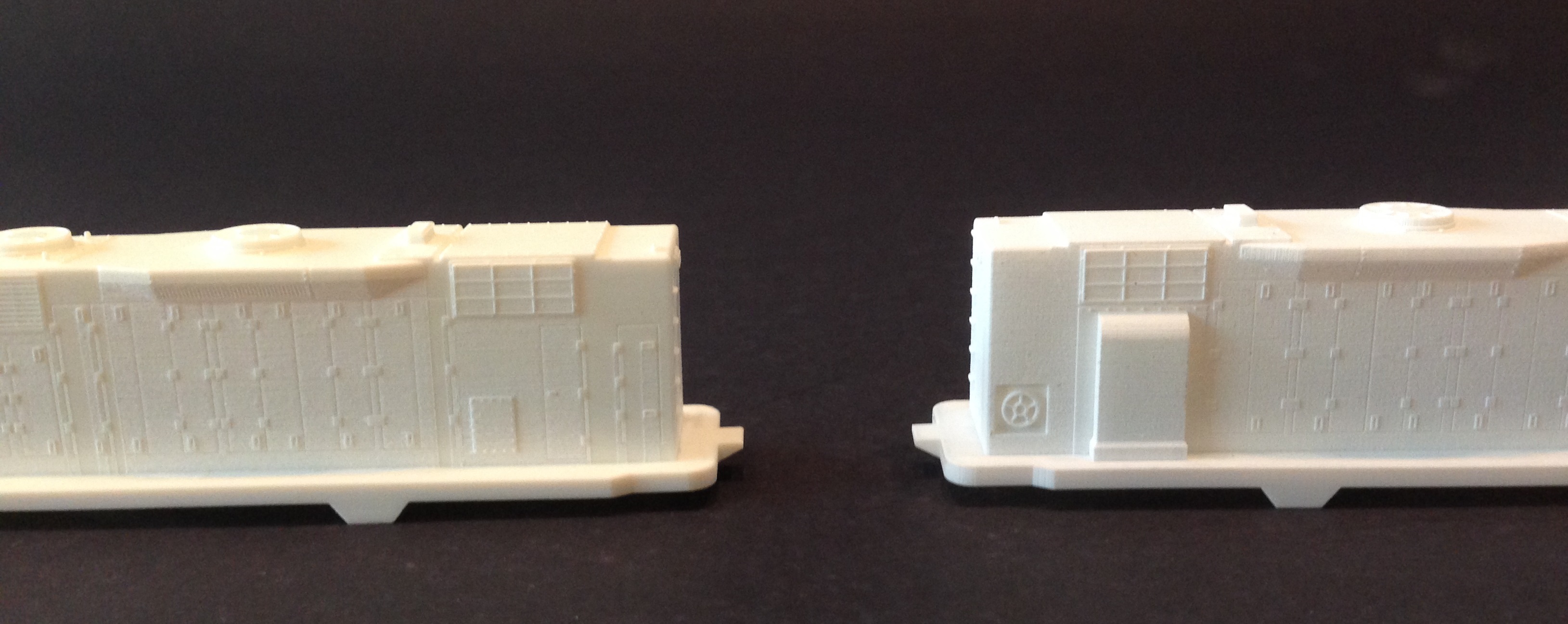
This shell has been improved by the FXD print without altering the design model.

Mike Musick DD35 In FXD 4 Mike Musick DD35 In FXD 5The print process to make both FUD and FXD prints does not leave any support material marks and because of the high level of detail achievable I don’t think desktop printers are ready just yet to be considered as an alternative. This is particularly true for N Scale models, although as a test printer they do the job well, and for chassis and parts that are not always visible the Form 1 would be perfect.

The 3D Print Show also introduced me to some other companies whcih provide services like Shapeways.  One is I.Materialise who had an impressive display of printed materials.  Their full colour plastics were particularly interesting and I will be looking into what I can do with them later in the year.  Another useful 3D print service came from 3DPRINTUK who print in SLS; this is the same as Shapeways’ White Strong & Flexible material and in fact they use the same machines.  Their pricing structure is different and for multiple runs of small parts they work out a lot cheaper so I will be making good use of them.

Another product that looks like it will be very useful to anybody with a desktop printer, except the Form 1 style, is the 3D printing mat called Zinomat from 3DSVP.  This is a mat which prevents your 3D printed item from getting damaged when it is removed from the build plate, as can sometimes happen.  This mat is in two parts; the first fixes itself to your build plate, the other is magnetically fixed to the first.  Once the print is complete you simply pull up the magnetic mat, then as it is flexible, it allows you to gently roll the print off the mat.

There was also a section of the show dedicated to software for running 3D printers.  3DPrinterOS allows you to connect your 3D printer to the Cloud which means you can send prints to it from anywhere in the world.  They also offer enhanced slicing tools, model fixing tools and better connectivity to improve the way your 3D printer runs.

The 3D Print Show wasvery interesting and highly informative about the current state of home or desktop printers. It has made me consider getting one for home use, although only as a testing device.  I will certainly go again next year and maybe by then the technology will have improved so much that I can’t say no.

Getting back to my normal 3D printing activities I currently have a few orders being printed by Shapeways and in my next posts I will be sharing them with you.

A Visit to the McKinley Railway

The weekend before last I was invited to visit the Mckinley Railway and in this post I will share with some pictures and video of the layout as well as a description of why this layout has been given the title, ‘Britain’s Most High Tech Model Railway’.

The Mckinley railway belongs to David Townend and with the aid of some fellow modeling friends he has built a wonderful model railway that does more than first appears.  The railway is a British outline OO Gauge layout set between 1958 and 1972.  David has modeled the main line section between London Kings Park Station and Manchester Park Street Station.  Along the way the line passes though the stations of Birmingham Broadway and Mckinley Road.

When you first walk into the actual layout room you are greeted with the sight of London Kings Park Station.

McKinley Railway Vist May 2015 - 02

This is a terminus station with six stub end passenger lines, a parcels depot, an engine facility and three coach sidings.

McKinley Railway Vist May 2015 - 19 McKinley Railway Vist May 2015 - 20

Although it is difficult to see, all the lamps in the yard are lit.

McKinley Railway Vist May 2015 - 21 McKinley Railway Vist May 2015 - 22

McKinley Railway Vist May 2015 - 18

The locomotive facility has both steam and diesel servicing facilities and a turntable which is located just to the right of the engine house in the photo below.

McKinley Railway Vist May 2015 - 23

The in and out lines leave the station over a steel bridge with the locomotive servicing area behind.

McKinley Railway Vist May 2015 - 01

The lines then meet a double track main line which navigates its way through the railway room.  Below is a track plan of the layout’s visible sections; if you click on the image it will display bigger.

mckinley_high_levelThe layout has two double track main line loops folded into the room.  The longest is 60m long and the other is 45m.  To ensure all this trackage does not make the room over congested there are a lot of hidden track and staging areas which are shown on the plan below.  The letters on the plans correspond to the joining sections between the two plans.

Model Rail 4.3pi The other large station is Manchester Park Street and this is also a large terminus station. As with London Kings Park it has stub end platforms, although only four.  There is also three carriage sidings, a large engine facility, freight yard and industrial area.

McKinley Railway Vist May 2015 - 40

McKinley Railway Vist May 2015 - 13

Behind the lovely station shown above is a busy scene which has been very nicely modeled and I was allowed to take some pictures inside with the building removed.

McKinley Railway Vist May 2015 - 10 McKinley Railway Vist May 2015 - 11 McKinley Railway Vist May 2015 - 12 
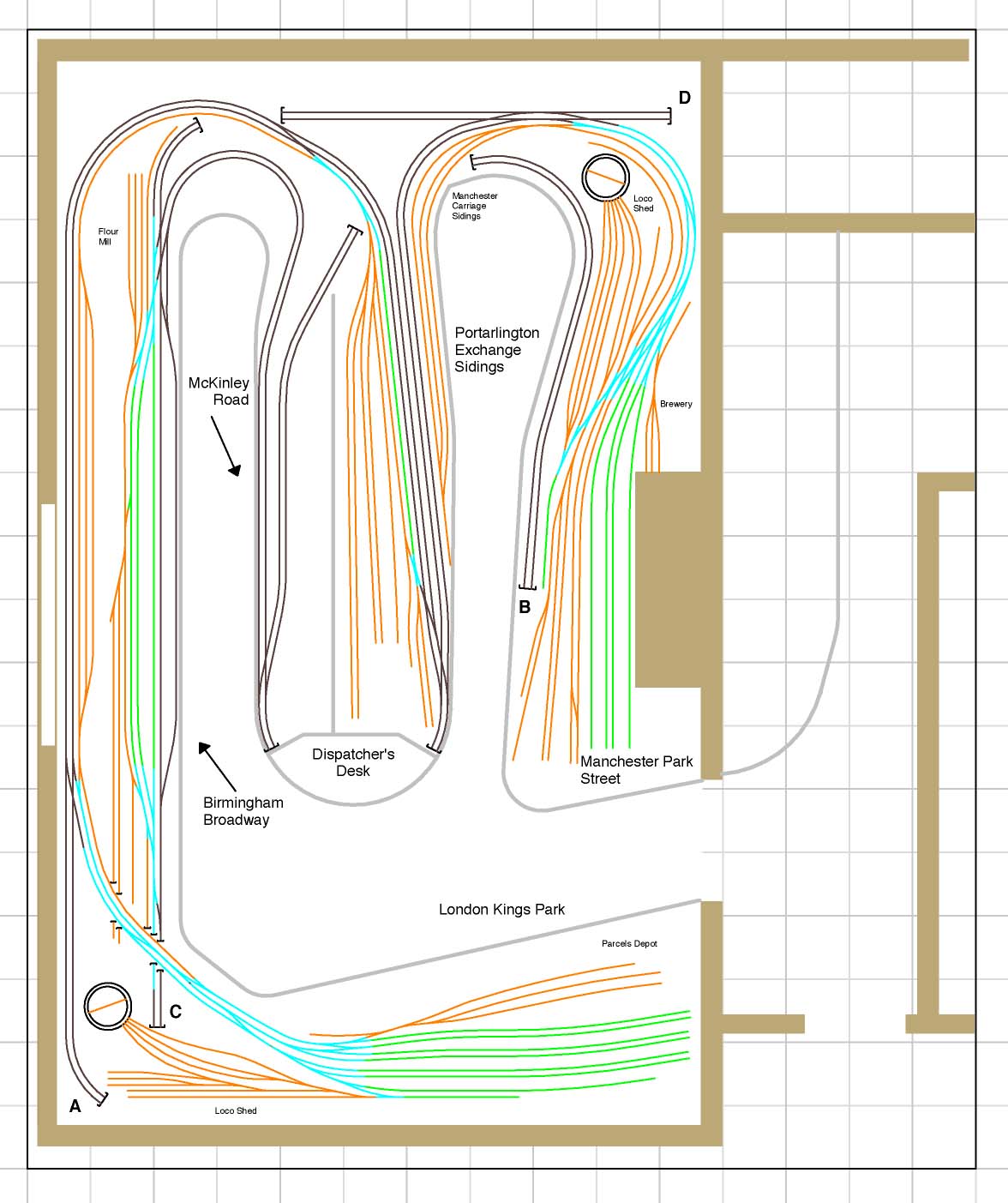
Because of the larger engine facility and goods yard the throat to the station is complex and the track work is very impressive.

McKinley Railway Vist May 2015 - 03

All of David’s track has been weathered and looks very realistic.

McKinley Railway Vist May 2015 - 14 McKinley Railway Vist May 2015 - 04 McKinley Railway Vist May 2015 - 05

At the back of the engine facility is another turntable.

McKinley Railway Vist May 2015 - 37 McKinley Railway Vist May 2015 - 38

The larger of the two through stations is Birmingham Broadway.  The station has four through platforms, a freight yard, flour mill industry and engine facility.  This station is situated under the only window in the room and it happened to be a lovely day outside so the light here made it a bit hard for my camera phone to capture the scene in all its glory.

McKinley Railway Vist May 2015 - 24

The coaches on the high level are in the coach sidings for London Kings Park Station.

McKinley Railway Vist May 2015 - 26

McKinley Railway Vist May 2015 - 28 McKinley Railway Vist May 2015 - 27 At each end of the station there is a signal box controlling the train movements, even though the back of the this box faces the operators David has detailed and illuminated the interior.

McKinley Railway Vist May 2015 - 16

This signal box also controls the access to the engine facility at Birmingham Broadway.  The two tracks nearest the signal box are the main line.

McKinley Railway Vist May 2015 - 17 Another large area on the layout is Portarlington Exchange Sidings.  This is a large freight yard alongside both double main lines which converge before passing under the dispatches desk.

McKinley Railway Vist May 2015 - 39 McKinley Railway Vist May 2015 - 15 The final main area is the small station of McKinley Road.  This is a small country station on one of the double main lines positioned just after the two diverge.

McKinley Railway Vist May 2015 - 31

McKinley Railway Vist May 2015 - 29

Leaving McKinley Road the double main lines change direction and elevation.

McKinley Railway Vist May 2015 - 30 
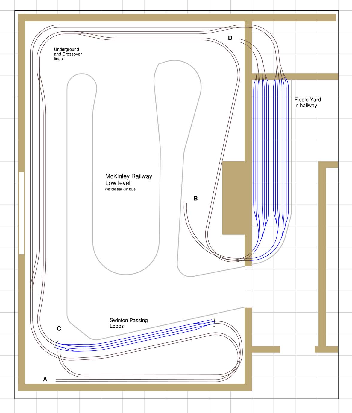
The final part to the layout are the staging areas; as you may have noticed from the track plans above there are several hidden sidings around the layout but the main staging area is in the adjoining room.

McKinley Railway Vist May 2015 - 07Each main line has four staging tracks.

Now you may be thinking that although this is a very nice layout what gives it the title of ‘Britain’s Most High Tech Model Railway’.  Well, firstly, this layout is fully DCC controlled which gives it all the advantages that come with DCC such as sound and lights.

Secondly, the layout is computer controlled.David has designed his layout so that it can be operated as a conventional model railway or as a fully functioning busy British main line single-handed.  I am sure at some point those of us who have used DCC systems, or DC systems that have more than one controller, have operated two or more trains at once and it was fun untill something went wrong because you were watching one train while the other was busy pushing a 10 coach train into the engine shed!

David wanted to create the feeling of this busy railway but with a controllability that ensured things did what they should do.  To achieve this the McKinley Railway’s 650m (2000ft) of track has been split into 90 separate blocks all controlled by occupancy detectors from Digitrax.  Each block or section has its own signals which are automated either by the occupation of the block in front, or by the computer.

The 150 points or turnouts on the layout are all powered by Tortoise point motor machines which are connected to Digirtrax DCC stationary decoders.  This whole system is connected together via the Digitrax LocoNet system and linked to a PC.  David uses software from Freiwald Software called TrainControler.  With this system David was able to map out the railway and tell the computer where each of the block sections are and how long they are, where all the points or turnouts are, what trains are on the layout and where they are.

Once the system knows all of this the operator could, say,, run a train from London Kings Park Platform 4 to Manchester Park Road Platform 2 and the system would set all the necessary points and run the train.  Then whilst that train was trundling around you could say run a train from Birmingham Platform 4 to Manchester Platform 1 and it would also do it.  But as the first train would also be coming up behind the second train on the same tracks, the system works out where and if the trains will meet and will prevent them from colliding.  The system also knows what the different trains are and knows the priority of each.  So if the train from London was an express and the train from Birmingham was local it would allow the express to pass the local without holding up the express.

When you factor in 100+ different trains in the layout the benefit of this really becomes clear.  David has pre-programmed several sets of movements into operating sessions, for example, a typical day in 1964 with all the movements between London, Birmingham and Manchester plus the rest of the UK represented by the staging yard.  The computer will work though them all in the correct order, moving trains around the layout, stopping local trains at the small station, moving them aside for a fast express, holding incoming trains at stop signals while others leave through the busy station throats.

When I first heard about this my thoughts were although it is very clever would it be any fun.  The answer is yes, because the human interaction element is still 100%.  On a typical operating session there are four to six operators each controlling a yard or station.  For example at the London Station, every train that comes in needs to be turned around.  This involves pulling the coaches back with a shunter to release the locomotive, the locomotive then needs to be sent for service and turned.  The parcel vans need to be shunted and sorted.  New trains need to be made up from the coach sidings.  This is a big operation and can keep one operator busy for ages.  Once a train is ready to depart a switch is set that tells the computer that train is ready to go and it can have control over that line.  The operator then gets busy with another train while the computer will take the train out to its destination.  I had the pleasure of operating London Station, in fact there were two of us, and while we were immersed in the shunting there were trains coming in and out and moving all over the layout which gave the feeling of a busy railway which is just what David wanted.

What amazed me was how smooth everything was, and I don’t just mean the locomotives I was controlling.  I have seen trains running before with automated systems and they tended to stop erratically and accelerate to max speed very quickly.  In this layout trains pulled out of stations gracefully and glided to a gentle stop.

This was achieved in several ways, firstly every locomotive on the railway has been speed matched and recorded in the software.  This means that when David sets the speed on any controller to 20mph the locomotive will do a scale 20mph; that is a great advantage of DCC.  Different locomotives have top speeds set depending on what they are; slow for freight, medium or fast for express.  The system knows all the distances and the speed performance of the engines so it can work out how to smoothly control the train.

David has also replaced the standard OO coupling with US style Kadee couplings which are much more reliable, and look better.  He has also correctly weighted everything to keep trains uniform and ensure they stay on the track. This created a problem in that a lot of the UK motive power commercial available are not good pullers; so David has re-motored most of his stock.  Below is a class 47 diesel with an Athearn motor taken from a US diesel.  The extra weight of the big fly wheels give the engine the traction and power that it needs.  He has also improved the power pickup on his locomotives and lighted rolling stock.  Because of the extra weight he has added to the engines he was able to remove the traction tires which improved the power pickup.

McKinley Railway Vist May 2015 - 06

All these improvements and modifications help to ensure the railway runs trouble-free.

To help the operators understand what is going on with the layout around the room are large display panels which show the layout in diagram format  They include point direction indicators, signal settings indicators and train locations.  Each block section has an orange light whcih illuminates when there is a train in the section.  The one below shows the hidden tracks.

McKinley Railway Vist May 2015 - 08

These panels show the visible main lines.

McKinley Railway Vist May 2015 - 09

Below is a video I took of a passenger train leaving London Kings Park Station for Manchester with a stop at Birmingham.

Here is a much better video that was taken by David showing the Midland Pullman doing the same trip.  The sounds in the station at the beginning are coming from the DCC sound decoder in the train.

David is in the process of expanding the layout into the next room.  The extension will included a large number of storage tracks with lots of trains parked up behind each other.  When one is sent out onto the layout the computer will shuffle all the others forward.  On the top of the large storage facility will be a new scenic section; David is planing on making this countryside and industries.

You can read more about the McKinley Railway on David’s website here.  He also has more videos on his You tube site which you can find here.

My visit to the McKinley Layout was a fantastic experience and I look forward to seeing it develop as the extension is built.

Next weekend I am off to the London 3D print show and will be looking at all the new technology with interest.  I will be there on the Friday if anybody would like to meet up.  In next week’s post I will tell you what I discover that might be of use to the Model Railroad and Railway world.

New Pages in the Shop – Etched Metal Additions

When I first set up this blog/website all of the models I offered came from my Shapeways shop and the few etched brass Additions that went with those models were only available on request.

I now offer several etched metal Additions for my own locomotive shells and there are more on the way.  I will soon be offering etched metal Additions for other models as well as my own.  To start with these will include handrails and details for early Atlas N Scale EMD GP7/9 locomotives and handrails and details for Con-Cor’s N Scale U50s.  I am now also producing other etched metal Additions such as my Chain Link Fence which you can read about here.  This fence is also on the cards to be produced in HO Scale.

Because all of these items are not made to order, as with 3D printed items, I have started to build up a stock and I have added a section to my shop on this site so you can buy them directly.  If you click on the shop tab at the top of the page you can navigate through to the relevant sections.

As more etched products are developed I will add them to the shop.  The N Scale Chain Link Fence is due to be added next week.

The ‘Buy Now’ buttons link directly to a PayPal checkout page where you can adjust the quantity if you want more than one. You can then pay with a PayPal account or if you prefer directly with a credit or debit card.

I always intend to keep some in stock, however now and again I may run out but it only takes one week to replenish from my etching manufacturer.

I have also added this same function to the Short Rapido Couplings as it is cheaper for me to print them in bulk, passing the saving on to you.  They will be available in packs of 20, ideal for a HST set, for £5.00 GBP plus postage.

If there is a specific item that you would like etched, such as handrails to replace oversized ones on a locomotive, then please let me know.  I am always happy to discuss new projects.  You can contact me through the contact page or directly at jamestrainparts@yahoo.co.uk.

A Baldwin RT-624 for the Pennsylvania Railroad in XHD

Towards the end of last year I shared with you my designs for a Baldwin RT-624 for the Pennsylvania Railroad, you can find the post here.  In the post I said that the RT-624 would be the first of my kits to be available in the XHD material.  In this post I want to show you how some of the XHD parts came out.

XHD stands for Extreme High Definition and is a term 3D Systems use for their 16 micron layer thickness setting on their Projet 3D printers. The majority of my 3D printed parts are printed by Shapeways in their Frosted Ultra Detail material.  FUD is also printed on a Projet machine at a 29 micron layer thickness, 3D Systems call this UHD or Ultra High Definition.  With 3D printing layer thickness, the lower the number the better the quality of the print.  But that does come at a price, with a smaller layer thickness the 3D model will take longer to print.

My first order of XHD prints was for four RT-624 kits as shown below.  The shell in the middle is a Shapeways print in their FUD material and the shell on the left has a set of  brass Additions train phone antenna test fitted in the roof.  The four XHD shells are shown here as delivered from the printers.

RT-624 XHD First Print 1

The first thing you notice is that the XHD prints are blue, whereas up untill now all my prints have been white. They are not blue because they were printed at a 16 micron layer thickness but because they were printed in a different material.  Shapeways use 3D Systems’ VisiJet® M3 Crystal material for the FUD prints but my 3D printer in London uses 3D Systems’ VisiJet® M3 Procast material.  The main difference, apart from being blue, is that the Procast is designed for lost wax jewelry casting and is perfect for very small details.  It is still as permanent as the Crystal but it has a slightly lower tensile strength and higher tensile modulus, which means that it is just that little bit more flexible and therefore less brittle.

The main question is how much better is the 16 micron layer thickness compared to the 29 micron?  I must point out that the FUD shell used for this comparison has not been cleaned as thoroughly as normal; it still needs some of the powdery residue cleaning off.  Below are the kits in both layer thickness. Initially they look pretty much the same.  The Shapeways FUD model has all the detail, everything fits perfectly and it has been used to make some fantastic models, please see the RT-624 Gallery here.

RT-624 FUD Kit RT-624 XHD Kit

It’s only when you get very close that you can start to see any differences. Looking at the two images below the roof of the locomotive is curved and in the FUD the curve is not quite as smooth as in the XHD.

RT-624 FUD First Print 1 RT-624 XHD First Print 2

Orientation also plays a big part in how well a 3D print comes out.  The top of the print will always be the best finish and any area that comes into contact with the support material also runs the risk of a slightly rougher finish.  These XHD prints were printed as if they were sat on the locomotive chassis.  This is the most expensive way of doing it because, just as if you were printing an upside down bath tub, the whole of the locomotive shell had to be filled with support material to print the top.  The benefit of this is that all the detail on the top comes out very clearly.  In the photo below you can see the lifting brackets and bolts around the exhaust stack are crisply printed. The details are still printed on the FUD model and are just as visible but they are just a little bit fuzzy. Don’t forget these details are tiny, the lifting ring is only about 1mm (0.039″) wide.

RT-624 XHD First Print 3

With smaller parts such as the fuel tanks, as you can see in the image below, it is very hard to see the difference between the FUD and the XHD prints.

RT-624 XHD First Print 4

With the trucks the two differences I could see were firstly that the XHD had a better definition on the tiny springs cast into the frame, and secondly the FUD has a better overall look. Both printers have heads that move over the print and the higher the definition, the more any offset calibration will show up in the print as vertical lines. So although the XHD print has better detail, the lower definition FUD print doesn’t show these vertical lines. Both prints show the horizontal lines made by layering the material as they print and the XHD layers are much smaller, but it has the added vertical lines from the moving print head.

RT-624 FUD First Print 3 RT-624 XHD First Print 6

Again with details like the cab interiors and horns it is very hard to tell the difference between XHD and FUD as you can see below.

RT-624 XHD First Print 7

RT-624 XHD First Print 8

Another advantage with specifying the XHD orientation is the quality around the sides is uniform, that is to say it is the same on all four sides.  Sometimes with the FUD prints one side can be rougher than all the others if it was on the bottom next to the print tray.

As with the FUD prints the XHD has to be cleaned to remove the waxy material left over from the print process.  Below is a shot showing a FUD print, an XHD print in the middle and a cleaned XHD print on the left.

RT-624 XHD First Print 9

The cleaning process has taken some of the blue colour out of the print, here are some more shots of the model after it has been cleaned.

RT-624 XHD First Print 10 RT-624 XHD First Print 11 RT-624 XHD First Print 12

As you can see in the photo above the XHD can still suffer from roughness under overhanging details, and as with the FUD this area will need a little scrub.  I find a toothbrush does this nicely.

So all in all is the XHD print better than the FUD? Well, I think it comes down to personal preference as well as your budget.  Currently the XHD prints are about three to three and a half times the price of the FUD prints. The really fine detail is sharper on the XHD but once painted the difference may not be so clear.  The XHD has the advantage of having a uniform finish on the sides but it can still suffer from rough areas which come into contact with support material and under overhangs. The calibration of the particular print machine can affect the quality of the 16 micron print head, causing vertical lines.  It may also depend what you want to use the 3D printed shell for; on smaller, more personal layouts where you are closer to your trains it is important to have as much crisp detail as possible, whereas on larger layouts when you are at least a few feet away from the trains such small detail may not really be visible.  RT-624 XHD First Print 13

I think the detail on the XHD prints is superb, and I’m really excited that 3D printing is able to offer such high definition, particularly for us N-scale modelers. However, in my particular layout the cost of these prints is a little high compared to the FUD which is still a very good print. I anticipate that this level of XHD printing will become more viable to mid-budget modelers like myself in the future. If you have the budget, I would recommend these XHD prints.

If you would like any of my products printed in XHD please contact me through the contacts page and I can give a quote.

In next week’s post I will be sharing with you the finished O scale UP excursion train tenders and letting you know how to get them.

Happy New Year and a Look Back at 2014

Happy New Year!

For this week’s post, being the first post in 2015, I thought I would take a look back over the 3D printed and brass products from last year.

The year started with the completion of my N Scale EMD DD35 locomotives as pictured below with a U50 and GP38.

DD35s and U50

The kits were released in both powered and dummy versions, the powered unit uses a modified Bachmann DD40AX chassis, below is a before and after photo of the first modified chassis.

DDD35 & DD4AX Chassis

Further development of the chassis led to the central corridor also being cut out, as shown below, to match the corridor connection in the 3D printed shell.

DD35 Chasssis Mk2

This greatly improved the realistic look of the locomotive. Below is SP no. 9902.

SP DD35 9902 8

The final improvement to the DD35 kit was the introduction of my etched Brass Additions for this locomotive.  This composed of a full set of etched brass handrails, as shown below.

DD35 Additions Set

EMD DD35 With Brass Etched Additions 5

The first run of DD35 brass Additions were made from 8 thou brass and although they were made to exact scale sizes this did make them a little hard to work with.  The later sets of brass are made from 10 thou brass and look even better as well as being easier to handle.

Both versions of the DD35 can be found here, and an instruction sheet showing how to modify the DDA40X chassis can also be found here.  I have 10 thou sets of brass Additions available for this locomotive so if you would like a set please get in touch through the contacts page.

DD35 & Friends 4

To make use of the spare Bachmann DDA40X shells that were left over from the DD35 builds I also released a DDA40X dummy chassis.

DD40AX Dummy 2

The chassis kit includes trucks, bolster pins and the main chassis section.

DD40AX Shell 4

It was designed to clip into the Bachmann shell and to utilize the spare fuel tank which clipped on to the new chassis.  This particular model also received axle wipes to collect power for the circuit board.  Below is a video of the dummy DDA40X running on the back of a coal drag with working lights.  Note the DD35 running as the third powered locomotive.

The DDA40X dummy chassis kit is available here.

My next kit to be released was my N Scale Union Pacific Excursion train water tenders.

UP Water Tender 4 (Mark Peterson)

(Modeling & Photos By Mark Peterson)

These were made available in the post 2007 rebuild configuration as shown above, then in the pre-rebuilt configuration as shown below.  Both kits include the main shell, chassis, trucks, ladders, headlights, tool boxes and bolster pins.

UP Water Tender 6 (Mark Peterson)

(Modeling & Photos By Mark Peterson)

In each configuration there are two body styles; with the rebuilt tenders this is simply the inclusion of flag plates on one of the tenders, whereas with the pre rebuilt set the piping configuration is different, as with the prototype and shown below.  The tender on the right has more piping on the roof.UP Water Tender 7 (Mark Peterson)

(Modeling & Photos By Mark Peterson)

Later in the year I also released the rebuilt tenders in HO Scale, as shown below.  As HO is lot bigger I was able to add a little bit more detail. The HO kit comes with all the same parts as the N scale ones, just bigger.

BR HO Modular Group With UP Tender - NMRA 2014 20

This then led to even bigger things; O Scale!  Below are all three scales together.

O Scale Tender - Comparison 4

O Scale Tender - Comparison 5

The O Scale kits are almost ready and will be available very soon and the N scale and HO Scale kits can be found here.

As well as big projects last year I also did several small detail items.  The first was my steel dog house kit to be used to add detail to steam tenders.

Steel Dog House 1

This design is for the dog houses used by the Norfolk and Western on their Y6b locomotive tenders as shown below.

Dog House 1

The dog house kits can be found here and are available in different quantities.

The next big project was another N scale diesel locomotive, this time a Baldwin DT6-6-2000.

DT6-6-2000 Gallery

This kit is designed to drop onto an Atlas C-628/C-630 chassis without any modifications required, except for rotating the trucks. The kit includes the main shell, handrails, engine crew with cab interiors and replacement truck side frames as shown below.

DT6-6-2000 Test Print 6

Although this locomotive was designed on the configuration used by the Atchison, Topeka & Santa Fe Railway, some modelers have done their own thing with it.

MNF1204 By Jeff King - 2

MNF1204 By Jeff King - 1

(Modeling & Photos by Jeff King)

This kit is also offered with a set of Brass Additions which include handrails and sun shades as shown below.  This set was also first offered in 8 thou brass and has since been upgraded to 10 thou brass giving a better look and feel.

DT6-6-2000 Additions Set

Below is a work in progress photo by Brian Stewart showing the brass handrails prior to painting.

DT6-6-2000 WIP(Brian Stewart) 1

This locomotive was also further developed by Baldwin into the RT-624 or DT6-6-2400.  The new locomotive was predominantly purchased by the Pennsylvania Railroad and not to disappoint my East Coast modeling friends I also further developed the kit as shown below.

Baldwin RT-624 Kit

There were lots of small changes made to the model but a few of the bigger ones included the addition of a replacement fuel tank, new style trucks and the extra brass Additions, particularly the famous Penssy Train Phone Antenna.  The brass etched details for this kit are made from 12 thou brass and look fantastic.  Below is a work-in-progress shot of Chris Broughton RT-624 with the brass parts added.

PPR RT-624 (Chris Broughton) 2
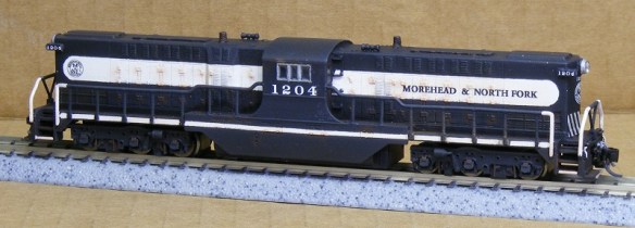
And here is Chris’ finished locomotive.

RT-624 Button

PRR RT-624 8355(Chris Broughton) 2

The N Scale DT6-6-2000 can be found here and the RT-624 can be found here.  Brass Additions for both locomotives can be ordered directly from me, please contact me through the contact page.

I also made some replacement parts for damaged locomotives last year, the first was a new drive shaft for one of my MRC/Roundhouse 2-8-0 steamers.

Sierra 2-8-0 No 28

The replacement part consisted of a new drive shaft directly replacing the original, which had been lost at an exhibition.

MDC Drive Shafts

This also led to a replacement drive shaft kit for the N Scale Atlas 4-4-0.

Atlas Drive Shaft Button

This replacement kit also contained the connecting parts at either end of the drive shaft as shown below.  These were the parts which had split on this particular locomotive.

Atlas 4-4-0 3D Printed Drive Shaft - Clened

Both kits worked well and allowed me to repair my two broken steam engines.  The MRC/Roundhouse 2-8-0 replacement drive shaft can be found here, the Atlas 4-4-0 drive shaft repair kit can be found here.

Another replacement part was for my N Scale Rowa/MRC Y6b steam locomotives.  As standard these don’t have a working front coupling or pilot and I wanted to double head mine so I released a replacement front pilot which could be fitted with either a Z or an N Scale Micro-Trains coupling.

Rowa Y6B Pilot Test Fit 1

Rowa Y6b Finished Pilot N 2

The kit makes the front pilot totally functional without affecting its cornering abilities.  Below is a short video of a pair of Y6B double heading round a very tight curve.

Both the Z Scale and N Scale coupler versions of the N Scale Y6b replacement pilot can be found here.

Last year I also released some other coupling replacement parts, firstly came my fixed link couplings.

Fixed Coupling 1

These are designed to replace Rapido style couplings but leaving the rolling stock permanently coupled together as shown below.

Fixed Couplings

This is particularly useful for locomotives which are permanently consisted together such as the set of three Con-Cor E7s pictured bellow.  They all share one DCC decoder and have wires running through the corridor connections. To ensure they don’t come uncoupled and pull on the wires I have installed my fixed link couplings.

IMAG0242

E7 Coupling 2

The fixed link couplings are available in a variety of lengths and quantities and can be found here.  If you require a different length or quantity please contact me though the contact page and I will be happy to add them to my shop.

The second replacement coupling was aimed more at the British N Gauge trains and is a short replacement Rapido coupling designed to reduce the distance between coaches to make them appear more realistic.  Below you can see two sets of N Scale Graham Farish HST coaches; the near side set have the standard Rapido couplings, the far side set have the new shorter ones.

HST's Coupling Closeup 2

The replacement short Rapido couplings can be found here.

Some of my smallest 3D printed items from last year were my N Scale super detail re-railers as shown below on the truck of a GP20 and hanging under a FA2 locomotive.

Re-Railers Type 2 On GP20 - 2.jpg

FA1 with Type 1 Rerailer - Close UpThese come in both a truck mounted version, which can be found here, and locomotive mounted versions, which be found here and are available in different quantity packs.

A replacement part was also needed for one of my favorite locomotives.  My N Scale Con-Cor 4500 Gas Turbine.  As delivered this model has a fuel tank instead of the correct battery box between the trucks so I have made available a replacement part that simply fixes on with the same screw.

Gas Turbine Batter Box - Clean 1

The battery box for the 4500 Gas Turbine can be found here.

To find out more about any of the parts and kits I have touched upon you can use the search facility at the top right of the screen at the end of the menu options.  This will lead you to all posts about a particular part or kit and you’ll find a lot more images, videos and information.

As well as all these new 3D prints I also visited and exhibited at several model Railroad/Railway exhibitions and conventions around the UK, here are some of the ones I covered in posts throughout the year.

Benson Winter Meet 2014 – NMRA (BR)

N Track Convention – Bournemouth

Fordingbridge Model Railway Exhibition – April 2014

The NMRA (BR) Annual Convention 2014 – Part 1

The NMRA (BR) Annual Convention 2014 – Part 2

The NMRA (BR) Annual Convention 2014 – Part 3

Poole & District Model Railway Society’s 2014 Exhibition

The Bearwood Group’s Running Meet

The Gosport American Model Railroad Group’s Running Meet

And that just about wraps up 2014 for James’ Train Parts.  2015 is going to be an exciting year with many new parts and locomotives coming out as well as developments in the 3D printing world in general. And there’s some great exhibitions coming up, including the NMRA(BR) Convention at the former signalling training school in Derby.

My first big project for this year, as some of you may have guessed, will be the massive Alco C-855 in N scale which I am greatly looking forward to and this engine will also have etched brass Additions and will be available in both dummy and powered versions.

Thank you for following what I’ve been up to in 2014, and I hope you’ll enjoy the New Year with me.

The Run Up to the NMRA (BR) Convention

This coming weekend is the National Model Railroad association (British Region) annual convention, The Seashore Extra 2014.  I will be hosting a clinic on the Saturday entitled ‘How 3D printing works and how it can help you’.  So this week’s post will be a little shorter than usual as I am busy getting ready for the show.

This year the convention will be at the Carrington House Hotel in Bournemouth, and for  those who can make it to the convention my clinic will be at 11.00am on Saturday.

Here is a link to the NMRA (BR) convention web site if you need directions and any other information.

Last week I said I would get back onto the HO Scale Union Pacific water tender project and I have made progress with it although not enough to share with you now but it will be ready for the convention.

The HO kit is now available through the Shapeways site in both FD and FUD materials and I will cover the finished model in a later post. Although the FUD is higher-priced compared to the FD it will give you a slightly more detailed finish. You can get them here.

I’m looking forward to meeting all of you who can come to the convention and for those who can’t make it I will be posting up pictures and videos of all the layouts over the next few weeks.