Quick & Easy Ways to Ballast Track

Over the years I have tried all sorts of methods to ballast track.  Some have been very time-consuming and some have just looked rubbish.  In this post I will share with you a method I have found to be fairly quick and easy and also gives good results.

Ballasting track is a key part of building a model railroad or railway.  Not only is it necessary for making the track-work look right but, just like the real thing, the ballast holds the track permanently in place.

The current layout which I’m working on is an N Scale modular layout and forms part of the Gosport American Model Railroad Groups ever-growing layout.  This particular module, New Mills,  is a small country halt next to a group set of factories.  The halt is used mostly by the factory workers and small town nearby.  Most of the trains pass without stopping so rather than platforms the tracks outside the halt have been boarded over so passengers can access to the local passenger cars via their steps.  Below is a photo of the left hand end of the module  The main line enters on the left nearest to the front.  It splits into two tracks that pass the station depot and then rejoin each other before leaving from the right hand end.  The third line with the end of a GP38 sat on it is the entrance to the factory sidings.

Balisting Track 1Before I even think about ballasting track I always do lots of running on the layout to make sure everything works okay.  The track is glued down onto a cork road bed which in turn is glued to the module top.  The cork is important for a few reasons which I will cover in a bit.  In the picture above you may have noticed that the track has been weathered.  This is not a necessity but it adds the realism I like to see; railroads are not a clean place.

I have several methods of weathering track.  First there is the spray paint method.  This can be done with an airbrush or aerosol can.  For the bulk of this module I used a grimy brown color aerosol.  Before spraying I removed everything from the module and simply sprayed along the tracks.  Then I quickly wiped the rail heads with a cloth to remove the paint.  Once the paint had dried I also ran over the rail heads with a track rubber to totally remove any paint residue.  Since doing that I have also added a few more bits of track but as I don’t want to risk spraying other stuff now fixed to the module I used a brown wash to weather the rails.

Balisting Track 2

Making a wash from paints is fairly easy but I find this the quickest.  Once the pot is shaken up the wash inside simply paints on.  I tend to roughly brush over the ties and rails then brush again with no wash on the brush.  This removes any excess wash and gives a mixed finish.  As before I wipe the rail heads over with a cloth.  Once you start to weather your track any new sections stand out as you can see in the photo below.

Balisting Track 3

Once all the track is weathered and had a chance to dry I tested it by running a few trains. Then it’s time to add some ballast.  Ballast comes in all sizes and colors.  For our group modules we stick to the same make and colour for continuity which is Woodland Scenic Fine Gray ballast.

On the real railroad the track is laid on top of a deep bed of ballast, then more is poured on top and packed or tamped down tightly around the ties.  Because the track is on a bed of ballast it is easy for the track gang to raise or lower the track to ensure smoothness as well as adding any special enhancements such as super elevations on corners.  Also this means the track is raised off the floor and the ballast acts as a natural soak away to stop water from flooding the tracks. Given most track ties were timber this was a good thing.

On the model railroad adding a bed of ballast is not very practical so we use a layer of cork.  Then when the ballast is poured on and covers the cork it will look like a nice deep bed and form the correct shoulder or slope on either side.

To start with I simply pour the ballast on in the right area trying to gauge the right amount.  Then using my finger I run it along the center of the tracks spreading the ballast evenly around.

Balisting Track 4

Then to get the right finish I use a small paint brush to carefully move the blast around.  This works for most of it but there will always be the odd bit that gets in the wrong place.

Balisting Track 5

The main area to worry about is the inside of the rail as this needs to be kept clear for the wheel flanges to run in.  I find the best tool for cleaning this is a small watchmakers screwdriver which can be run along the inside of the rails and knocks off any stray ballast.

Balisting Track 6

The area in the photo above is a little thick with ballast by intention.  Normally ballast is leveled off just below the tops of the ties and the excess is moved down the line.  However at that particular section the track is flanked at both ends by a boarded walkway and roadway so the excess ballast tends to get left there and forms a ridge down the center of the track.  On the other side of the roadway the ballast starts to get a bit thinner as the track crew have more room to spread out the ballast.

Balisting Track 7

When it comes to turnouts it’s okay to add ballasts around the rails but the gaps between the check rails and inside the frog (the V shape in the middle) must be kept clear.  Again the small screwdriver is ideal for this.  It is also important to keep the moving areas free so keep moving the turnout blades thoughout the process.

Balisting Track 8

Once the ballast is in the right place I use an old freight car with big flanges as a tester.  I run it up and down to make sure there is no ballasts where it should not be.  I also change the turnouts.  Note: if you have solenoid operated turnouts the sudden bang will dislodge the ballasts and can also bounce it into areas you don’t want it.  Although this can be useful for removing it if you have got some in the turnout blades.

Once all the turnouts can be thrown, manually, and the test car runs up and down, it’s time to stick the ballast down.  For this I’m using a product from Noch that was recommended to me.

Balisting Track 9

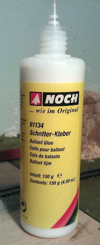
I have used other ballast glues and made my own in the past but this product works better than any of them.  The dispensing nozzle allows you to carefully and accurately drip or drizzle the glue where you need it and it doesn’t cause any lift in the ballast.  By ‘lift’ mean the ballast raising up onto liquid glue that has not soaked into the ballast.  It does not bubble or flow along the ballast causing washouts; it simply runs in.  In the picture below I started in the center of the track from the left, and although I was a little heavy-handed the ballast glue still soaked in anway.

Balisting Track 10

I then worked around the tracks covering all the ballast.

Balisting Track 11

Before the glue has a chance to dry I did one more test with an old freight car. This is why I use an old freight car as you get glue on the wheels. Then I left it overnight to set fully.  The next day all the ballast was dry and any surplus could be picked up with a vacuum cleaner.  Because the rail heads might have been covered in the glue I used the track rubber again to brighten them all up so I could do a proper test with a loco.

Balisting Track 12

The next step, which I still have to do, is to weather the ballast.  Out on the main line the ballast would be fairly clean but at the ends of a station area like this there would be coal, oil, grease and diesel spills where locomotives would have been stood.

BalistingTrack 13

You may also be wondering why I haven’t ballasted the track in the industrial area?  Well, this track work is under the obligation of the factory owner to maintain, not the railroad, and the ballast will be lower and dirtier, not to mention full of weeds at the ends of the tracks. To do this I need to mix up some ballast with other products and I will share that with you in a later post.

The Great Dorset Steam Fair 2015

This week’s post will be a bit different in that it won’t be about model trains, it’s not even about trains!  But it is about steam, lots and lots of steam, because I’ve been to the 2015 Great Dorset Steam Fair and for those of you who have never been to or even heard of this event I thought I would share some of it with you.

The UK has a proud history of mechanical machinery and throughout the year steam rallies and heritage shows can be found up and down the country with all sorts of vehicles and machinery on display.  But the Great Dorset Steam Fair is the largest and is also now known as the ‘The National Heritage Show’.  The event is quite literally huge and covers and area of 600 acres.  It is open to the public for five days; many of the exhibitors stay for seven or eight.  On average the show draws in 200,000 visitors with tens of thousands camping on site to enjoy the night life. This year’s show was the 47th and was also the biggest I have been to so far.  The show is the largest of its type in Europe.

What makes the event so special is the machinery is not just on display; it is working and doing what it was made for.  There are 5 main display rings or arenas and the largest is the heavy haulage ring.  In here you won’t find vehicles parked up with judges walking up and down but a cacophony of sound, color and smoke as heavy loads are dragged up and down the hills behind traction engines, vintage lorries & steam rollers.

This year I was only at the show for one day and it’s not possible to get round it all and see everything in that time but I did get lots of photos and some videos for you.  These were all taken on my ageing mobile phone so the sound quality is a little rough but it gives you an idea.  It was also an overcast day but that didn’t stop the crowds.

So what does all this sound and look like?  Well below is video taken alongside the heavy haulage ring with some of the traction engines running past.

The heavy haulage ring, referred to by the drivers as the ‘Play Pen’, is in the shape of a dog bone to allow easy turning at each end.  All the movement is in an anticlockwise direction.  The lowest part is in the center and at either end is a hill which makes the engines work hard and pleases everybody.  The nearest hill to the center of the show is smaller and is where all the trailers and loads are picked up or parked.  The far end is the largest hill and requires a lot of skill to get the big loads up it.

The main vehicles in the heavy haulage ring are traction engines and these come in all shapes and sizes.

GDSF 2015 Heavy Haulage Ring 5 GDSF 2015 Gigantic 1

The traction engine or road locomotive above is a McLaren called “Gigantic” built in 1911.  It was designed as a heavy haulage tractor, and has been put back to its World War 1 livery when it would have been used to pull large guns and supplies to the front line.  They were called ‘road locomotives’ as a ‘locomotive’ was term used to describe a railway engine.

Alongside the ring, traction engines wait for their turn, below ‘Britannia’ sits in the sun.

GDSF 2015 Traction Engine Britannia

GDSF 2015 Traction Engines

The engine below is great example of an agricultural (general purpose) engine which has been worked hard.

GDSF 2015 Traction Engine Timber Clad 1 GDSF 2015 Traction Engine Timber Clad 2

Sitting by the ring for any period of time you will see a huge variety of machinery pass by.

GDSF 2015 Heavy Haulage Ring 1 GDSF 2015 Heavy Haulage Ring 7 GDSF 2015 Heavy Haulage Ring 6 GDSF 2015 Heavy Haulage Ring 4 GDSF 2015 Heavy Haulage Ring 3 GDSF 2015 Heavy Haulage Ring 2

GDSF 2015 Traction Engines 1 GDSF 2015 Traction Engines 2 GDSF 2015 Traction Engines 3 GDSF 2015 Traction Engines 4 GDSF 2015 Traction Engines 5

GDSF 2015 Traction Engine With Load

Throughout the day there are different demonstrations in the ring, below are some photos of an exhibition of cavalry officers on horseback reenacting charges; they were attacking cabbages!

GDSF 2015 World War 1 Demonstration Houses 1 GDSF 2015 World War 1 Demonstration Houses 2 GDSF 2015 World War 1 Demonstration Houses 3 GDSF 2015 World War 1 Demonstration Houses 4 GDSF 2015 World War 1 Demonstration Houses 5

As the ring is so big the action carried on behind the horses and below is a video of some of the traction engines shifting the biggest load around the lower part of the ring before they tackled the big hill. Note, the traction engines were doing all the work, the truck was there for emergency brakes.

All sorts of different loads were available and throughout the day different engines pulled different loads.

Below is a team of engines pulling a huge transformer up the big hill, and down again.  The engine on the back is normally used as a braking engine.

The team rested at the top before making the descent.

GDSF 2015 Traction Engines With Transformer Load

All over the site there are traction engines, all singing with steam.

GDSF 2015 Traction Engine 2

Here is a video of one just passing by.

The engine below, ‘Leviathan’, is a portable engine used to produce power only as it could not move by itself.  This would have been towed to a site and used to drive anything from wood cutters to thrashing machines out in the fields.

GDSF 2015 Station Boiler Leviathan

As well as traction engines there were also steam wagons and lorries.  Foden was one of the major manufactures of steam wagons and lorries and below are some great examples.

GDSF 2015 Foden Steam Lorry 1 GDSF 2015 Foden Steam Lorry 2 GDSF 2015 Foden Steam Lorry Boadicea

The steam lorry below was designed as a heavy hauler with its twin axels for added traction.

GDSF 2015 Foden Steam Lorry Lake & Trinidad 1 GDSF 2015 Foden Steam Lorry Lake & Trinidad 2

Sentinel was another big manufacturer and below are some perfect examples.

GDSF 2015 Traction Engine Sentinal Steam Lorry 1

GDSF 2015 Sentinal Steam Lorry Hovis

The steam lorries were, for their time, very fast and in the video below you can see the ‘Hovis’ Sentinel steam lorry charging through the heavy haulage ring on its way up the big hill.

What helps make the lorries so fast is they are chain driven, not directly geared like the traction engines.  Below you can see the chain casing on the rear axle with the chain just protruding out the bottom.

GDSF 2015 Steam Lorry Drive Chain

GDSF 2015 Steam Lorry 1 GDSF 2015 Steam Lorry Little Lady

The steam wagon below has also been returned to its World War 1 livery.

GDSF 2015 Traction Engine World War 1 Steam Lorry

Here is another video of steam lorries doing their thing in the heavy haulage ring.

And where there are lorries, there are cars.  Steam cars, that is.

GDSF 2015 Steam Car 1 GDSF 2015 Steam Car 2

And here is a video of them charging round the area.  For a fee of £5 you could get a ride in one with all proceeds going to charity.

The vehicle below is a diesel-powered World War 1 gun tractor built in the US for the British Army.

GDSF 2015 World War 1 Gun & Tractor

We also had a World War 1 tank crawling around the arena.

GDSF 2015 Traction Engine Worls War 1 Tank 1 GDSF 2015 Traction Engine Worls War 1 Tank 2

It was a fairly slow mover as you can see in the video below; it actually crept up on me as I was filming by the gate to the arena.

As well as all the steam there was also hundreds of heritage cars, lorries, buses and motorbikes on show around the site.  My personal favorite are the Scammell trucks.  Below is a Scammell Constructor named ‘Viking’.

GDSF 2015 Scammell Viking

GD2SF 2015 Scammell Truck 2

Here is a Scammell Highwayman.

GDSF 2015 Scammell Truck 1

And my favorite, the Scammell Explorer.  It’s a World War 2 tank recovery truck.

GDSF 2015 Scammell Explorer 3 GDSF 2015 Scammell Explorer 2 GDSF 2015 Scammell Explorer 1

And if you happen to have one lurking around your barn that you don’t want, please let me know!

And of course the big Scammells got their chance to play in the heavy haulage ring.

GDSF 2015 Heavy Haulage Ring Scammell 2 GDSF 2015 Heavy Haulage Ring Scammell 3 GDSF 2015 Heavy Haulage Ring Scammell 4 GDSF 2015 Heavy Haulage Ring Scammell

The Scammell Explorers make the best sound and you can hear them as they enter the ring in this video.

Once they had done a few laps and calmed down they started on the big loads.

Old Glory magazine had a big marquee at the show with several engines under repair.  I think the one below need a bit of work but I reckon we will see it steaming again one day.

GDSF 2015 Traction Engine TLC

Another type of traction engine comes with a crane.  This made them very versatile and elsewhere on the site they were in use moving logs, barrels and machinery.

GDSF 2015 Traction Engine With Crain 
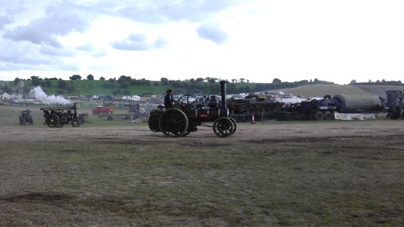
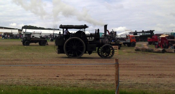
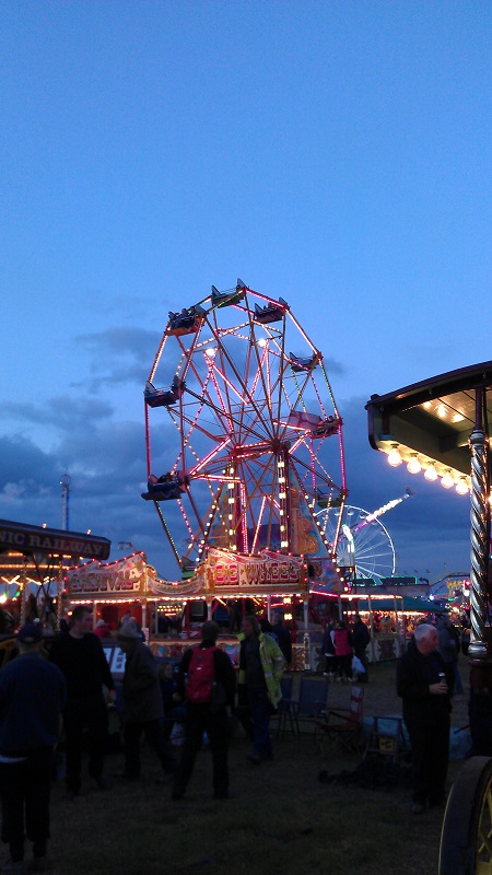
Steam rollers were also a big part of the show and there was a whole area dedicated to them although I didn’t get time to visit that part of the show. They were actually being used to create the new roads through the site.

GDSF 2015 Traction Engine, Steam Roller & Steam Lorry Line up

Alongside the heavy haulage ring was a sectioned-off strip given to the miniature engines and these realy do come in all shapes and sizes.  There was a field full of them; here are a few.

Below we have miniature traction engine ‘Little Lew’

GDSF 2015 Miniature Traction Engine Little Lew

In the photo below we have a big miniature ‘Lady Of the Lake’ and small full-size running next to each other.

GDSF 2015 Miniature Traction Engine Lady Of the Lake

Miniature (if you can call it that!) traction engine ‘Galanthus’.

GDSF 2015 Miniature Traction Engine Galanthus

Miniature traction engine ‘Black Pearl’.

GDSF 2015 Miniature Traction Engine Black Pearl

Miniature traction engine ‘Bagpuss’.

GDSF 2015 Miniature Traction Engine Bagpuss

This one was tiny!

GDSF 2015 Miniature Traction Engine 1

And this one is my friend’s miniature traction engine, ‘Emily’.

GDSF 2015 Traction Engines Emily 2

She has just been rebuilt and I was lucky enough to have a ride around the ring with her.

GDSF 2015 Traction Engines Emily 3GDSF 2015 Traction Engines Emily 1

As well as working machinery there are also fields of auto jumble where you can buy all sorts of things. Spare engine, anybody?!

GDSF 2015 Auto Jumble Old EngineAt intervals around the show were the fairground organs and a lot of them were steam-powered or at least driven by a traction engine.

GDSF 2015 Fair ground Organ 3

In one of the big fields to the side of the show, the ploughing engines could be found working hard.

GDSF 2015 Plowing Engine 1

The ploughing engine is almost the same as a traction engine but it has a longer boiler to make way for the large winding drum underneath.  Although you can’t see it at the top of the field there is another ploughing engine.  The cable from both engines is attached to a plough and they take it in turns to pull the plough across the field.  To speed up the operation the plough is often double-facing.  This means you don’t have to turn it arround.  In the image below you can see the plough with three people sat on one side of it to weigh it down, the engine on the left is pulling.  Once it gets to the end the people will sit on the other side and it will swing over like a seesaw.  The engine which was pulling will give two blasts on the whistle and the other engine will start to pull.

GDSF 2015 Plowing Engine 2 GDSF 2015 Plowing Engine 3 Below is a video showing the ploughing engines working and in the middle of the video you can see the cable winding onto the drum.

And not to be left out here are two miniature ploughing engines doing the same thing.

Elsewhere on the site the showman’s engines are hard at work powering the fairground, and attractions.  And when I say powering, I don’t mean with mechanical power but electricity.  The showman’s engines are again similar to traction engines but they have a full roof and an extra section on the front that overhangs the smoke box door.  On this over hang is positioned an electric generator, sometimes the bigger ones have two.  The engine below, ‘Lion’, was powering a ride behind it; you can see the wires hanging down from the left hand side of the generator.

GDSF 2015 Showmans Engines Lion 1

GDSF 2015 Showmans Engine Lion 3

On the side of the generator mount are two gauges measuring the voltage and current draw; ‘Lion’ was producing 110 volts and 200 amps.  Each time the ride started up the amps shot up to almost 400 amps and ‘Lion’ gave a satisfying bark as the governer kicked in to maintain the constant speed.

GDSF 2015 Showmans Engines Lion 2

Most of the organs and stage shows had one or several showman’s engines providing power.  Below is ‘Cary On’ with the ‘Gavioli’ Organ and stage show.

GDSF 2015 Foden Showmans Engine Carry On

Showman’s engine ‘The Masterpiece’ and living van.

GDSF 2015 Traction Engine The Masterpiece

Showman’s engine ‘Evening Star’.

GDSF 2015 Showmans Engine Evening Star

Showman’s engine ‘His Lordship’.

GDSF 2015 Showmans Engine His Lordship

GDSF 2015 Showmans Engines 7

But the biggest concentration of showman’s engines is the line up powering the big fairground.

GDSF 2015 Showmans Engines 5

GDSF 2015 Showmans Engines 1

GDSF 2015 Showmans Engines 2

I didn’t count them but on one side there must be 50 showman’s engines of all sizes.

Here is showman’s engine ‘John Murphy’.  You can see how big it is by the ladder they use at the back to get into it.

GDSF 2015 Showmans Engine John Murphy 1 Behind the lineup is the fairground which is full of new and vintage rides and attractions.

GDSF 2015 Showmans Engines 3 GDSF 2015 Showmans Engines 4   GDSF 2015 Showmans Engines 8

Showman’s engine ‘Peter Pan’.

GDSF 2015 Showmans Engines Peter Pan

Showman’s engine ‘King George V’.

GDSF 2015 Traction Engine King George V

Showman’s engine ‘Supreme’.

GDSF 2015 Showmans Engine Supreme

Parked all over the site are the living wagons which you often see being towed behind the traction engines.  Some of these are truly fantastic and very comfortable.

GDSF 2015 Traction Engine Living Van

A lot of the traction engines return to their living wagon at night and get put to bed.  At the top of the big hill several engines get covered over as the sun goes down.

GDSF 2015 Traction Engines Put To Bed

But that is not the end of the show. The heavy haulage engines may be shut down but the fairground comes to life and this is when the showman’s engines have their moment.

GDSF Showmans Line Up

As the sunlight fades away the steam-powered lights start to come on. Here is showman’s engine ‘John Murphy’ again all powered up.

GDSF 2015 Showmans Engine John Murphy 2

GDSF 2015 Showmans Engine John Murphy 3

Showman’s engine ‘Dolphin’ was producing a good 200 amps powering one of the Big Wheels.

GDSF 2015 Showmans Engine Dolphin

GDSF 2015 Fair Ground

Showman’s engine ‘Ex-Mayor’.

GDSF 2015 Showmans Engine Ex-Mayor

Showman’s engine ‘Obsession’.

GDSF 2015 Showmans Engine Obsession 1 GDSF 2015 Showmans Engine Obsession 2

Showman’s engine ‘QUEEN OF GT. BRITAIN’.

GDSF 2015 Showmans Engine Queen Of GT Britan GDSF 2015 Showmans Engine Roof GDSF 2015 Showmans Engines 10

As well as all the night steam activity there are also several huge entertainment marquees with live music to suit all tastes.

I didn’t stay ’til midnight this year, so I don’t have photos for you in total darkness, but trust me, with so many showman’s engines lit up it is a sight which photos can’t do justice. One thing to look forward to when you do stay ’til late is all the showman’s engines sound their whistles at midnight, and that is an impressive noise.

On the way back to the car park I passed through the fair and past the biggest of the Big Wheels.

GDSF 2015 Fair Ground Big Wheel

There was so much I didn’t get to this year, or didn’t photograph, including steam saw cutting, steam thrashing (bailing of straw etc), horse ploughing, horse-drawn vehicles, vintage tractors, classic motorcycles, fields of vintage commercials and army vehicles, tractor pulling, huge arts and crafts tents, model tents, massive food halls, birds of prey, fields of stationary engines and all sorts of shows and entertainment.

Next year’s show will start on Wednesday 31st of August 2016 and runs til Sunday the 4th of September 2016, maybe I will see you there.

Painting and Weathering Rocks

In last week’s post I shared with you some of the work I have been doing on my new N Scale modules for the Solent Subdivision.  I focused on using homemade rocks to form a river canyon; you can find the post here.  In this week’s post I’m going to share with you a fast and simple way to color and weather your rocks.

The first thing you need to do is get some reference material to help work out what colors your rocks are going to be.  A simple internet search for river canyon or railroad canyon will bring up all sorts of results.  For example here is a link to an image of a river canyon with similar colors to mine.  Typically base colors for rocks will be gray, brown, yellow or red.  This will depend on the geology in the area you are modeling but mostly it will depend on what you want it to look like.

Once you have decided on your color palette you can pick the paints or stains that you will use.  My rock faces will be based on brown and yellow.  Again I have turned to Woodland Scenics but there are plenty of suppliers of scenic paints or you could simply use cheap acrylic paints from a hobby store.  I am using Burnt Umber and Yellow Ocher as my base colors. Raw Umber is another good base color which will give a grayer finish.

Colouring Rocks 3

If you wanted to add a bit more red into the color palette Raw Sienna is a good choice but be careful as a little goes a long way and you don’t want to overdo it unless you want a strong red all over.

Because the cast plaster rocks and plaster cloth used to join them all together are porous it is better to stain them using a pigment rather than paint them.  This is because the pigment will be soaked up into the plaster and the colors will bleed into each other giving a cohesive look to the color.  Simple paints on their own would give a blotchy look because the color will stay in the area applied under the brush. The colors from Woodland Scenics are called pigments and are designed to be diluted with water; acrylic paints can be used in the same way.  The other main color I will be using is black and for this I have a simple black acrylic poster paint.

Using three separate plastic pots, one for each color, I prepare the pigments.  In the image below you can see I have added just a little Burnt Umber into the bottom of the pot.

Colouring Rocks 1

Then I have added water to dilute the pigment.  The bottle says to make the mix 1 part pigment to 16 parts water.  I tend to use a little less water with the lighter colors but it is all down to personal taste and you can also get different effects by changing the mix as you go. The main thing is to make sure the water and pigment are all mixed together.

Colouring Rocks 2

Using an old paint brush or sponge brush, or just a piece of sponge will do, start by dabbing spots of the diluted pigment onto the rocks in a random order.  The technique is called leopard spotting.  You will notice the plaster will instantly soak up the water from the pigment and the color will bleed away from the spot you touched with the brush or sponge.  I started with the Yellow Ocher as this will be my least dominant color.

Colouring Rocks 4

Then with the next color, Burnt Umber, I filled in the areas around the Yellow Ocher.  When doing this if you think there is not enough Yellow Ocher you can simply go back and add some more.  The main thing is to ensure all the white is covered.  Depending on the type of rocks you are modeling and your color palette you may also be adding in a third color such as Raw Sienna.

Colouring Rocks 5

Although the rocks are starting to look nice a lot of the details are still looking flat; that is to say the detail in the cracks  and crags are not showing as well as they could do.  Also the the rocks are looking very clean which is not very realistic.  To solve this I use my final color which is the black.  Again I have diluted the paint with water but this time I have done it roughly 1 part paint to 32 parts water.  I say roughly because whenever I do this I always try a little first then add more paint or water until I get it the way I want it.  Diluting it so much will make it into a wash rather than a paint and this is what we need to bring out the detail without eradicating the previous colors.  The wash is also applied with a brush or sponge and will run down into the cracks and crags a little before the plaster has a chance to soak it up.

Colouring Rocks 7

You can apply more or less of the wash depending on the finished look you are after.  If you think you have added too much and the rocks are now too dark you can simply add more of the other diluted pigments over the top.

Colouring Rocks 8

It is a good idea to keep stepping back as you work through the process because it can look different when you are not so close.

Colouring Rocks 9

On the other side of my canyon you can see all three stages from left to right.  When doing large areas of rock in stages it is a good idea to stagger the finish line, this will make it easier to blend everything together.

Colouring Rocks 10

Stepping back again you can start to see how the colors will work together.

Colouring Rocks 11

And finally here is a shot with all the rocks painted.  The green is simply an undercoat in the areas where there will be grasses and vegetation but you can see how the overall effect will look.

Colouring Rocks 12

Although the main rocks are finished the canyon is not.  I still need to add in lots of detail such as fallen rock, known as talus or scree, as well as all the vegetation before finally adding the water.  And I believe there is a small matter of a railroad trestle.

Using Your Rocks to Build River & Railroad Canyons

A few weeks ago I shared with you how I cast my own rocks using plaster and rubber or latex molds; you can find that post here.  In this post I will show you how to use the rocks to create large canyons and cliff faces.

For one of my new modules I am constructing a large timber trestle scene similar to the rendering below.

Trestle Module 1

In the scene the Warsash River enters the module from the front and runs downhill to the left, cutting a deep U shaped canyon in the softer rock, leaving a tricky area for the railroad builders to cross.

Trestle Module 3

What makes the crossing even more complicated is the line diverges at this point.  The Solent Sub Division continues to the right while the branch line exits through the back of the module via a rock tunnel cut through the remaining granite.  This gives the module the name ‘The Warsash Wye’.

To give myself as much flexibility as possible with the design of the canyon only the ends and the small island supporting the junction turnout have been made from wood.  The fascia has been cut to follow the contours of the terrain.  The rest will be built up using my home-made rocks and plaster cloth.

Warsash Canyon Creation 0

The river bed was installed using a thick cardboard  The river drops ten scale feet from entrance to exit and the bed is propped with more cardboard and glued where possible to give a good solid base.  A basic white glue is good for this.

Warsash Canyon Creation 01

Next the basic structure of the landscape had to be built.  For this I used strips of cardboard from an old box.  I believe McCain oven fries were the flavor of the day!

Warsash Canyon Creation 2

Even the back of the canyon had some card added up to the wall. The idea is to remove any large flat and square surfaces.  There is no particular science to this; it just needs to be a bit supportive and give the rough shape you want.

Warsash Canyon Creation 3

To give some stability to the structure another flat timber was added just under the hole in the back of the module where the branch line exits.  The timber was fixed securely to the back board and the cardboard strips could be fixed to it.  In the image below you can also see the timber island for the turnout. There is a Seep point motor under the timber.  The wires for track power were also installed at this point with lots of slack.  They could be added later but it’s easer to do this now.  The white you can see under the card strips on the left is a cube of polystyrene which had been glued to the inside of the fascia.

Warsash Canyon Creation 4

The strips of cardboard are glued together and I used a staple gun to hold it all together while the glue dried.  Where the strips meet the back board I used the staple gun for speed but still glued the ends to ensure strength.

Warsash Canyon Creation 5

Once all the card support was in place it was time to add the plaster cloth.  There are many manufacturers of this and I used a mixture of several I had to hand including Woodland Scenics and Mod Rock.  They are all basically the same although you may get a slight difference in color; this however is not a problem. The Mod Rock turned gray untill it had totally dried.

Although it’s lots of fun it can be a very messy activity so I didn’t take any photos of the work as it progressed.  I would also recommend putting some newspaper under the layout because you will get drips.

Warsash Canyon Creation 6

To apply the cloth you will need bowl of water, a good pair of scissors and be prepared to get your hands wet.

Warsash Canyon Creation 7

I cut the cloth into strips a little longer than the height of the canyon, then I dipped the strips into the water one at a time. Make sure you fully submerge the strips in the water. Then I draped them over the cardboard structure with each strip overlapping the last, helping to make the scene all one piece as well as strong.  The strips set fairly quickly and the shape of the canyon soon took form.

Warsash Canyon Creation 8

There is still some more to be added at the tunnel mouth but that will come later.  The deepest part of the canyon is where the river leaves the module and it is also quite narrow which made it a little tricky.  If you end up using lots of smaller sheets or simply adding several to ensure coverage that’s okay.

Warsash Canyon Creation 9

I put two layers of plaster cloth on some of the larger areas and staggered the joints, which adds to the strength and closes any holes which you can sometimes get when there is not much plaster on the cloth.  I then left the plaster to dry overnight, although it was probably dry within two hours.  At this stage I could simply paint the plaster rocky colors but I wanted to add the texture of a full rock face to the whole canyon.

This is where all the rocks I previously cast come in.

Lots of Cast Rocks

Taking some of the larger rocks I positioned them in ways that I felt looked natural.  This can take a bit of trial and error.  Once things started to fall into place I glued some of the larger ones down with white glue.  Then I was able to build up, adding more large rock castings and filling in around them with smaller ones.

Warsash Canyon Creation 10

By the time I had positioned rocks up to the level of the tunnel entrance I had also started to build up the cliff face to cover the tunnel.

I used some of the very large rock castings to form the steep canyon walls in the narrow section behind the turnout.

Warsash Canyon Creation 11

You will notice there are a lot of gaps between the rocks; this will be dealt with shortly but for now it is more important to make sure the rocks are firmly fixed in place.  Again I used white glue.  At this point I try not to get any of the glue on the face of the rocks as this will show when it comes to paint them.

Looking down the canyon the rocks looks rather out-of-place but this is how I intended them to look and once the next step is done they will look a lot better.

Warsash Canyon Creation 13

From a distance you can start to see how the rock face will look. I also glued in the outcroppings, for example the group to the bottom right of the photo below.  The rock glued to the back wall to the left of the unfinished area will form part of the tunnel opening.

Warsash Canyon Creation 14

Once all of the rocks are in place, or at least most of them, and the glue has had a chance to dry, it’s time to seat the rocks and blend them all together.  I do this by using more plaster cloth.  I cut the cloth into strips roughly 25mm (1″) wide by 130mm (5″) long, then I dip each strip in the bowl of water and push the cloth into the gaps between the rocks.  Using my finger I smooth out the surface which brings the small plaster particles to the surface and hides most of the fabric.  I keep adding strips untill the rocks all start to blend together.  I try to encircle all the rocks making them look like they are all one big piece.

Warsash Canyon Creation 15

At this stage I had also finished the top section with the tunnel opening made from rock castings.  I wanted it to look like the railway engineers had cut the rock back to form the opening

Warsash Canyon Creation 16

Looking down the Canyon now the walls all seem to be part of the same rock formation.

Warsash Canyon Creation 17

The rocks in the river bed also now seem to be a part of the landscape. And you can almost picture the river cascading down around them.

Warsash Canyon Creation 18

And again with the other end of the canyon I have placed rocks at the base of the walls and in the middle of the river bed.

Warsash Canyon Creation 19

There are still a few gaps but these will disappear once I start to color the rocks and add some greenery around the edges and in the cracks.

Warsash Canyon Creation 20

Overall I think the effect looks good. The next stage is to add some color but first the whole structure needs to dry.

Warsash Canyon Creation 21

In a later post I will share with you how to color the rocks to finally blend them all together as well as bringing out all the detail of the cracks and crags.

Making Rocks for Your Model Railroad

One thing I enjoy making on my model railroad is mountains with tunnels and bridges.  And for that you need a lot of rock.  In this post I am going to share with you how I make my own rocks, boulders, outcroppings and cliff faces.

The rocks I am currently making are for a modular N Scale layout but this process can be used for any scale.  And as with most things in model railroading there are hundreds of ways to do the same thing. This method is just one that I have found which works for me.

I have been asked in the past why I don’t use actual rocks on my layout.  The answer is that real rocks are very heavy and may not be the right colour for the scene that I’m modelling.  And they can be very hard to shape!  The weight is less of an issue for small areas on a fixed home layout and I have used them before, but for modular layouts the lighter you can make them, the better.

To make my rocks I use plaster or filler, depending on where you buy it from.  Different makes of plaster can effect the outcome so it’s worth thinking about what you will be doing with the rocks.  I have used the cheap powder filler from the local DIY store; this goes a long way but is fairly heavy when dry and again for modular layouts this is not so good.  Woodland Scenics make a product called Lightweight Hydrocal, pictured below, which is a plaster that sets fairly quickly and is very light.  This is ideal for rocks and I use it for most of mine.

Lightweight Hydrocal

To cast the plaster into rocks I use moulds.  I have a few commercially available rock models; mine are also made by Woodland Scenics.  They are made of rubber and are designed to be strong enough to be self-supporting but flexible enough to take out the plaster when dry without breaking the rock, although that is a common occurrence. Below is a typical Woodland Scenics mould.

Woodland Scenics Mould

Even though the moulds are reasonably strong with all the added weight of the wet plaster the sides can droop and if you are not careful the fluid plaster will spill out.  To prevent this I sit the mould on a bed of scrunched-up newspaper so, as the plaster is added, it settles down into the paper without tipping over.

The Hydrocal is very easy to mix. I use an old plastic bowl and wooden spoon.  First I add the plaster, about one and a quarter cups.  Then I add half a cup of water.  I mix all the powder in until the whole mix has the same consistency which only takes about a minute.  Then it’s ready to pour into the mould.  I would not recommend making bigger batches as the plaster starts to set fairly quickly and if you need to stop mid pour it might go off in the bowl.

The plaster sets in about an hour but I tend to leave it overnight as it can be a bit soft if removed too soon and breaks easily.  When it is properly set it will be hard and dry. Below are some rocks cast in the mould above.

Rocks From Woodland Scenics Mould

This is a great way to make rocks but there is a drawback.  If you are putting a lot of rocks in one area you soon run out of different types.  You can use the same rock several times by changing the direction but it can start to show.  Also, having used my Woodland Scenics moulds many times I am very familiar with the rock shape and can easily spot them on other exhibition layouts.

To get around this and to add diversity to my layout I have made my own rock moulds.  This is not as hard as it sounds and Woodland Scenics provide the tools for the job.  They make a liquid latex rubber which can be painted on to real rocks to make a mould.

Woodland Scenics Latex Rubber

I collected a selection of rocks based on shape and texture that I wanted for my layout.  I washed all the rocks to remove any dirt and loose material from the surface.

Rock Moulding 1
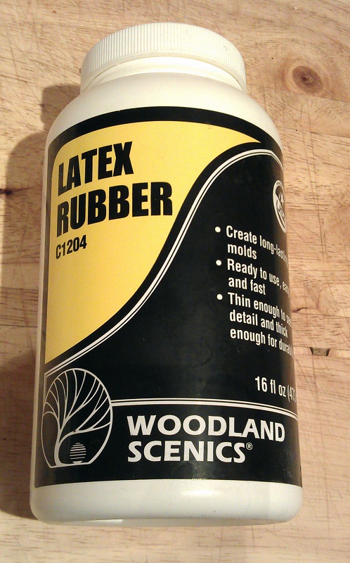
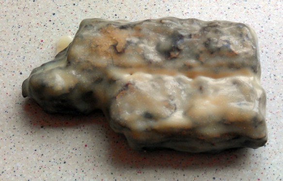
Then, once dry, I painted a fairly thin coat over the rocks top and sides.  A bit of preparation is a good idea when doing this, mainly making sure you have somewhere to put the rock down once you have painted it and also having some water or even better a sink near by to wash off the brush and clean up if required.  Dont expect to use the brush for anything else after this as it will become a rubbery lump.

Making the first coat thin is necessary to ensure the latex gets into all the detail on the rocks and to prevent any air bubbles from getting trapped under the latex.  It also helps the latex set quickly.  I would also recommend only doing a few rocks at a time so the latex in the jar does not start to form a skin.

Rock Moulding 3 
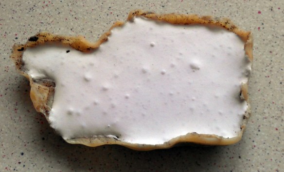
Once the section of rock I required was covered I placed it in a foil tray to set.  The latex rubber is white as it comes out of the pot but turns a translucent yellow as it sets.

Rock Moulding 5 Depending on the thickness the latex will take about half an hour to an hour to set.  Then another coat will need to be applied.

Rock Moulding 6 About three to four coats of latex rubber is required to create a good strong mould.  To make a very strong mould layers of gauze can be placed in-between the latex layers; but so far I have not had the need to do this.

Once the final layer has set, I tend to leave this overnight, the mould should then be a uniform colour.

Rock Moulding 9 Rock Moulding 8

The mould can be peeled away from the rock.  This can be started by rubbing the edge with your thumb.

Rock Moulding 10

Once the edge is lifted all around the mould it should peel away completely.

Rock Moulding 11 
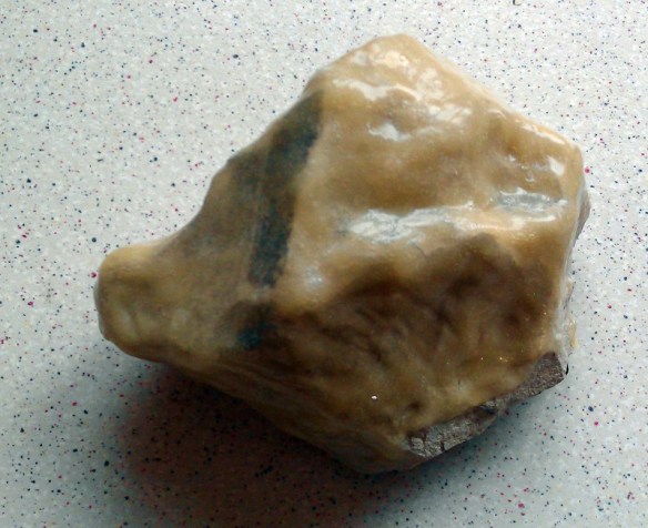
The mould is then ready to be used to cast a rock.  This particular mould only had three thin coats of latex and will need a little support to keep the same shape as the rock. This is actually a good thing as with out the support the mould will flex in a different direction every time I use it, giving me a slightly different rocks.

Rock Moulding 11-5

The plaster is mixed and poured in the same way as before and the final result is a rock similar to the original just as I wanted.

Rock Moulding 13 Rock Moulding 14

This method can be used on any surface that has the texture you want for your rocks.  Below I have a section of bark collected last year from a tree.  Now that it has fully dried out I will use it to make a mould.

Rock Moulding From Bark 1

Again the first layer of latex wants to be very thin as the bark details are fragile.

Rock Moulding From Bark 2

Rock Moulding From Bark 4 Rock Moulding From Bark 5

Once all three layers had set I removed the mould and poured in some plaster.

Rock Moulding From Bark 7

The latex did pick up some of the bark material which consequently ended up in the rock but that doesn’t mater and will blend in nicely when I colour the rocks.

Rock Moulding From Bark 6 Rock Moulding From Bark 9 I have used this process on large and small rocks with great success.

Lots of Cast Rocks

Now that I have a big pile of light weight rocks and boulders it’s time to fix them to the layout and colour them, which I will cover in a later post.

More Brass Additions

The English Summer is here and although I have been doing some more work on my current projects the call of the great outdoors has been too great.  So in this week’s post I am simply going to share with you some images of two forthcoming projects.

The first is a set of brass Additions to super detail the older N Scale Atlas GP7/9 locomotives.  The very early ones made by Kato are good runners but there were certain things which were not quite right.  The primary issue which led to this set of additions being made is the handrails.  EMD installed handrail stanchions made from folded plate not tubular sections.  This has been corrected by Atlas on their more recent locomotives.  My set of Additions, as seen below, has a full set of replacement handrails as well as many other parts all etched in 10 thou brass.

JTP Additions GP7-9

This fret also includes four sets of MU Hoses, two Sinclair antennas, three rear view mirrors, four windscreen wipers, two sun visors, seven sets of grab irons, one grab iron drill plate, two drop steps for the end handrails and two cab doors so they can be modeled in the open position.  The first run has already been etched and the parts are currently being tested for correct size and fit.

The second new project, which is somewhat smaller, is a pair of rear view mirrors, as shown below, for N Scale GE Genesis locomotives, in particular the P42 made by Kato.  Have a look at some pictures of real P42 locomotives and you will see them. Here is a link to a good example taken by Zach Pumphery.

JTP Additions P42 Mirrors

Interestingly they are not made opposite hand, that is to say the left and right are not a mirrored pair. The left hand side mirror is fitted in the configuration shown above, the right hand mirror is simply rotated 180° and installed with the small handle at the top.

As with the EMD GP 7/9 Additions these are still being tested but I will be making them available soon.  In the meantime it’s back to the other projects, unless of course the weather’s nice!