Using Second Hand Capacitors

This week’s post will be a how-to for a question I get asked a lot.  Can I use second-hand Capacitors?

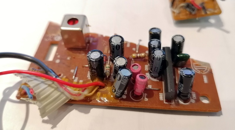
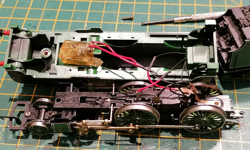
The reason I often get asked this is modelers often want to use second-hand capacitors to make StayAlive units for their DCC locomotives, and these can be very effective.  But where are they getting second-hand capacitors from?  Most electrical appliances have capacitors in them of one form or another.  A good example of this is an old stereo system I took apart for the motor.  Below you can see the main printed circuit board (PCB) and it has lots of black cylinders which are mostly all capacitors, and ideally sized to fit into small locomotives.

Even the smaller secondary PCBs have capacitors on them.

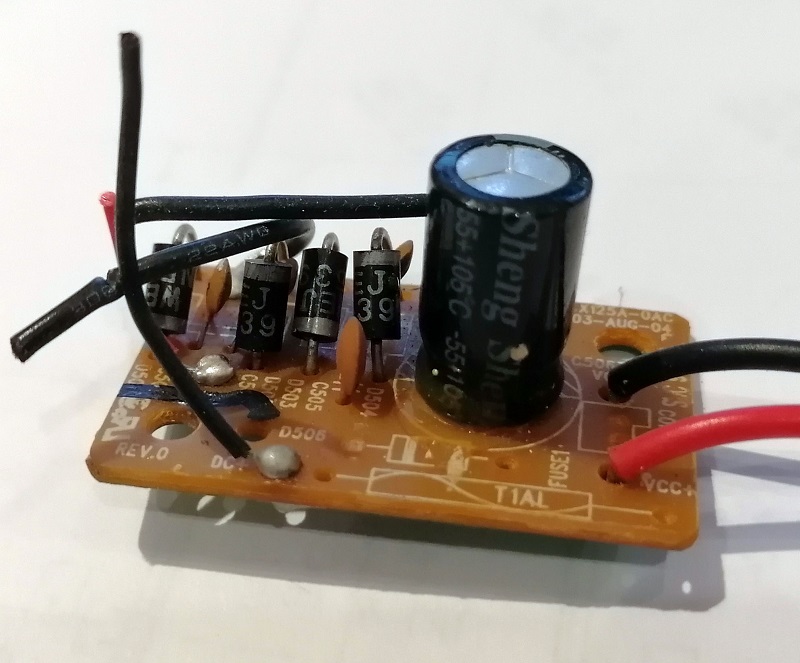
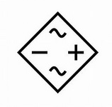
The main power input board below is a bridge rectifier, the smaller black cylinders are diodes, and it turns AC voltage into DC for the stereo to use, the nice big capacitor is there to smooth out the DC.

These capacitors are all soldered onto the PCB.  With a good soldering iron the capacitor can be removed without damage by heating the two soldered joints, once you have figured out which ones they are, and pulling the capacitor out. 

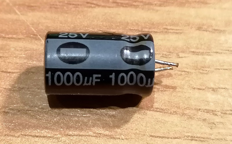
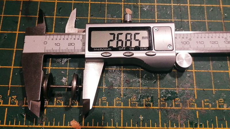
This capacitor has a working voltage of 24v and a capacity of 1000 microfarads.  The voltage is important because it needs to be higher than the voltage in the DCC locomotive decoder.  This normally does not exceed 16v, so a capacitor like this is ideal. 

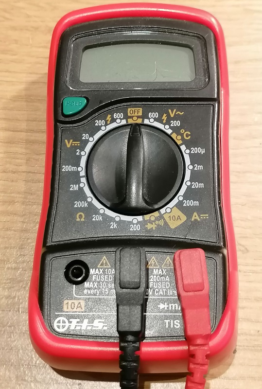
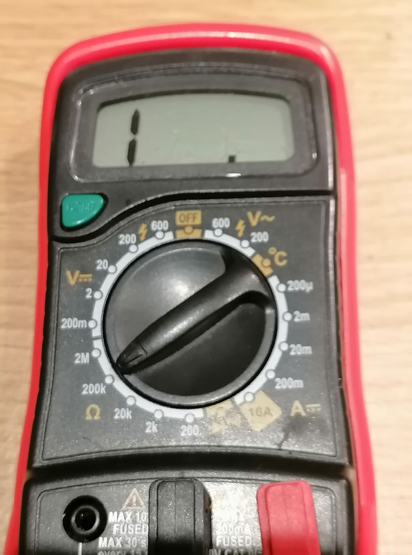
But I find the more important question is not whether second had capacitors can be used, its do the work?  Luckily there is a simple test to check this without any expensive equipment.  Some high-end multimeters have the ability to test capacitance but most do not.  Mine does not, but what it can do is test voltage and resistance.

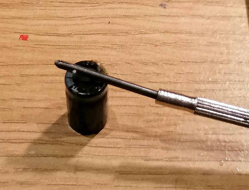
One thing to do before the test is to remove the charge from the capacitor, a full capacitor could damage the multimeter.  This can be done with a metal screwdriver by shorting across the two terminals.  Please note, this is okay for small capacitors in the Microfarad range used in modeling, I would not recommend doing this with large capacity capacitors with capacitance measured in farads!

The two settings I use are both on the left of my multimeter.  Below it is set to 200k ohms and is used for testing resistance.  I will also be rotating the dial clockwise by three positions to 2 which is a DC voltage measurement.

The way this works is first you discharge the capacitor.  Then, with the multimeter set to resistance, connect the probes to the capacitor.  Black negative to the capacitor negative and red positive to capacitor positive.  The capacitor negative is normally clearly marked.  As the multimeter has a battery inside when the probes are connected to the capacitor it will start to draw and store power.  As the stored power increases the resistance will increase so on the display you will see a steady increase in resistance from 0 to infinity.  If there are any big surges or erratic readings, then the capacitor is not working.

The second part of the test is to set the multimeter to volts DC and reconnect the probes.  This will measure the stored voltage and you will see it decease as the capacitor discharges through the multimeter.  Again this should be smooth.

As it happens the capacitor I took out of the stereo was faulty, probably one of the several reasons it didn’t work!

But to show you the principle, I created a short video of me testing a new capacitor.

So the answer to the question “Can I use second-hand Capacitors” is yes, but I would recommend testing them before spending any time wiring them into your locomotives.

If you have a similar question you would like to be answered or explained in more detail, please contact me and maybe I can help.

Adding DCC To Older Locomotives With Smoke Units

Hello all, my apologies for the silence over last month.  It’s been a very busy time and I’ve been doing a lot of work away from home making it hard to work on trains, draw and generally model railroad.  But I’m back and to start with I have a ‘How To’ to share with you regarding adding DCC to an older steam locomotive with a smoke unit.

A perfect example of this is the Hornby Schools Class 4-4-0 as shown below.  This is not to be confused with the new Hornby Schools DCC-ready locomotives which are a very different model.

These earlier models were only designed for analog or DC operation only.  They are tender driven with the tender wheels picking up power from one rail and the locomotive the other.  Adding a DCC decoder is fairly easy but what makes it complicated is the smoke unit.

With the loco shell removed and you can see the smoke unit which has been pulled out of the boiler.  Normally this locomotive only picks up power from one rail, as previously mentioned, but when Hornby added the smoke unit they added a pickup to both rails but this extra pickup only feeds the smoke unit.  This is because, as standard, there’s only one electrical connection to the tender via the drawbar.

In the image above I’ve run four wires through the loco cab into the tender where the DCC decoder and motor are.  Two are from the power pickups bypassing the electrical connection in the drawbar to utilize the extra pickups for the decoder.  The other two are connected to the common DCC wire (blue) and the auxiliary wire (green) and go straight to the smoke unit.

The smoke unit itself is an oil reservoir with a heating element in it.  It runs on 12v DC and sends out smoke when it gets hot.

Normally on DC or analog operation the smoke unit works very well, getting hotter as the locomotive goes faster because of the voltage increases.  But it also draws much more current than a headlight or other features.  So when connected directly to the DCC decoder, as shown above, the amount of smoke is restricted by the current capacity of the decoder.  The particular decoder fitted in this locomotive has a maximum current output of 250mA for its functions, which is not enough to make the smoke unit work.

To solve this some electronics can be added which will allow the smoke unit to draw power directly from the track, but still be turned on and off from the DCC decoder.  To do this I use a bridge rectifier and a relay.

The bridge rectifier, on the left, converts AC power to DC.  The DCC power in the track is basically AC with the DCC signal embedded. This device, which is a set of four diodes, will convert the power to a clean DC power supply that will drive the smoke unit as if it was on full power.  The relay is an electronic switch that can be operated by the DCC decoder and only draws a very small amount of power.  But the switch inside can be used to connect things that draw lots of power, such as the smoke unit.  This particular relay is a Double Pole Double Through (DPDT) switch, which means it can switch two separate wires between two contacts at the same time, but I will simply use it as an on-off switch.  I like it because it’s very small.

The two input connections on the bridge rectifier connect directly to the power pickups in the loco.  The outputs go to the smoke unit with one wire passing through the relay. The symbols on the bridge rectifier are shown below.  The two wavey lines are the AC connections and the positive and negative symbols are the DC.

The relay has 8 pins.  Pins zero and one are the two wires, common(blue) and auxiliary (green) from the decoder which turn the relay on and off. I used pins two and four for the smoke unit.  With the relay off they’re not connected, but when it’s on they are.

I soldered the wires to the components and used heat shrink to cover the bare wires as they could cause an issue if they touched the metal chassis.

Because the parts are small they can both be tucked into the boiler behind the smoke unit, so they’re out of the way when the locomotive shell is refitted.

This fitted DCC decoder has been set up so F1 turns auxiliary on and off.  When the locomotive is sat on a live DCC track pressing F1 will cause the loco to smoke even though it’s stood still.  This could never have been done on DC as the smoke unit needs to heat up and the train would already be moving before that happened.

These parts are readily available from places like Radio Shack, RS components or even some model shops and are an easy way to overcome the issue.   This can also be used when fitting an aftermarket smoke unit such as Seuthe.  I’ve fitted a pair of Seuthe smoke units to a double chimney locomotive using this method with great results.

Next week I plan to have some news on one of my upcoming 3D printed locomotive projects to share with you.

Adding Power Pickups by DCC Concepts

As well as the drawing I do for 3D printing I do a lot of train repairs and DCC installs, particularly sound installs.  These can sometimes be a bit tricky and I often have to use other products to make it work.  Normally I don’t do reviews of products but recently I found something that worked so well I wanted to share it with you.  In this post, I’ll show you what I did to add additional power pickups to a Hornby OO B17 with plastic wheels in the tender.

The B17 has been around for many years and every now and again it gets a facelift as parts are re-tooled and improved.  The most recent version is quite fantastic, but the previous one had, in my opinion, one major problem.  The tender was the same design from many years before, and still had plastic wheels.  The two pictured below are of this version; you can tell by the basic molded coal load in the tender.

This means although the locomotive had been re-tooled to include power pickups on all the drives, it still only had the pickup footprint of an 0-6-0.   For DC operation this is often just fine, but DCC, and in particular DCC sound, the decoder required an unbroken power supply and when you factor in dirty track, dirty wheels, and dirty pickups, the 0-6-0 footprint on this loco simply wasn’t working.

Looking under the tender you can see the plastic wheels and even the hole above the third one which allowed a strip of card with a rough surface to hang down.  A cam on the last wheel used to rub against the surface and make a kind of chuff effect; this dated back to the 80’s and Hornby called it their ‘Realistic Chuff’ effect.

The red you can see through the hole is a stay alive unit.  This locomotive is fitted with a Zimo Sound decoder, but even with the stay alive, if the loco stopped in the wrong place it wouldn’t start again without a push.

The axle for the wheels is simply a bar and the plastic wheels are in two parts.  This design has been repeated on many locomotives of early design.

The first problem is to find metal wheels to use.  The reason why it’s a problem is just about all the current metal wheels come with much shorter axles with pointed ends.  But the old Mainline or Replica Railways (which is now Bachmann) locomotives had metal wheels in their tenders which were the exact same size on long axles.  Of course, this does mean sacrificing another loco but six axles from two tenders is enough to do three Hornby locos as I’ve only replaced two wheelsets in each tender.  An afterthought would be to see if the plastic wheels fit in the Mainline or Replica Railways tenders?

I found two types of wheelsets in the Mainline/Replica Railways tenders.  Some, as with the set on the left, have metal wheels but a plastic axle which doesn’t end in a point.  The center and right side wheelset both have metal wheels and a metal axle, electrically isolated, with pointed ends.

As the original Hornby axle measured  26.35mm I wanted to get as close as I could.  Any longer will cause binding and make it harder to fit the new wheels.

The set with the plastic axle came in just under and worked perfectly without modification.

The set with the metal axle was ever-so-slightly longer, but this was easily remedied by filing off the points on each end of the axles.

As you can see below both types of wheelsets fitted into the tender and they all rotated  very well.

The second issue was how to collect the power from the metal wheels.  Over the years I’ve built many homemade pickup systems, normally from strips of brass that rub on the wheels at some point, but it doesn’t always work well and the pressure of a flat strip rubbing on the wheel creates a lot of drag.

Then I discovered DCC concepts’ gold plated bronze wheel wiper sets.

The pack contains 12 sets of wheel pickups, each picking up from both wheels and a pack of screws for mounting.

The actual pickup is a strip of PC board with two folded brass contacts, both gold plated.  The contacts have a rounded section to provide a pinpoint contact on the wheel which will reduce drag.  Next to the mounting hole are two solder pads, one for each side.

The rear simply has the connection between the pickups and the solder pads.

As you can see below the pickups fit perfectly between the wheels and provide just the right amount of pressure to ensure a great contact with the wheel.

Now it’s time to fit them.  With the tender shell removed you can see the metal weight.  It will be important to keep this as it’ll ensure the wheels keep good contact with the rails, but it’ll need to come off for now.

The weight was held in place with a few spots of glue.

With the new wheels fitted the pickups can be moved around until the ideal location is found.  You need to make sure the rounded part of the pickup is in contact with the middle of the metal wheel flange and not the plastic inner.

Then using a pin vice I drilled a hole, smaller than the screw, in the tender chassis using the hole in the pickup as a guide.  The screw will cut into the soft plastic of the chassis.

The pickups can now be fitted in place.  I also fitted the wheels again at this point to test everthing worked properly.

The screws were longer than the thickness of the plastic chassis and protruded out of the top. That’s why I removed the weight, and they need to be cut and filed down to refit it.

I refitted the weight using some Black Tack, it’s very sticky and malleable, which is ideal for this job.

The solder pad can now be linked with wire.  If you have a large soldering iron you may want to solder the wires on before the pickups are fitted to prevent caching the chassis with the iron as it will melt very quickly.

Lastly, I solder on two wires to connect back to the main locomotive pickup points.  It’s important to ensure you match the tender wheels from the correct side with the loco wheels or it will simply short out.

With the tender reassembled and all the wires connected it was time to test the loco, and it ran very well.  The best test was to raise the loco off the rails, so it isn’t picking up any power and see if the tender pickups worked on their own, which they did, as you can see in the short video below.

I could’ve fitted three sets to the tender, but after testing two proved to be plenty, and both the B17 locomotives from the first picture are now running equally as well as the latest version of this locomotive, which comes with factory fitted tender pickups.

These pickups from DCC Concepts are very good and, I think, very well priced because you get 12 in a pack.  I’ll certainly be using them again. I just hope they bring this product out for N Scale.  You can get the pickups direct from DCC concepts or at a stockist such as Model Railway Solutions in Poole.

Next week I’ll share with you some of the 3D printed parts which arrived last week.

Cleaning Track Inside Tunnels

Maintaining track and keeping it clean is one of those jobs we all hate but has to be done to keep the trains running.  In this post, I’ll share with you how I clean the track inside the tunnel on my Tehachapi module.

Cleaning the track really only comes down to polishing the tops of the rails.  But there are lots of ways to do it and, depending on the severity of the dirt, some work better than others.  Under general running the nickel silver rails pick up all sorts of grime from the wheels as they pass over, whether plastic or metal.  Any rolling stock, such as locomotives or illuminated items that conduct electricity, cause a fine powdery oxide to form, due to the electrolysis effect; this is when current passes through dissimilar metals.  When you wipe your finger along the rails and get a black streak, that’s it.

The environment the layout is stored in also makes a huge difference.  If it’s in a dry space with a constant temperature, such as a spare room, the rails will stay fairly clean as the powdery oxide will simply fall off the rails.  But layouts in sheds, lofts, and cellars, where the temperature can drop or any dampness gets in, will cause the powdery oxide to bond together into a film and the rails will become dirtier sooner.

Also, any lubricants can run down and get spread over the rails causing locomotives to wheel spin.  Smoke oils and over-lubricated locomotives can cause this.

The stronger type of dirt on the track is usually caused by building the scenery.  Glues, paints, and lacquers will always get onto the track somehow and these take a bit more to remove.

Once I’ve finished the scenery I always give the track a good clean with an abrasive track rubber.  Lots of manufacturers make these; I don’t recommend using anything like emery paper or sandpaper as they are too abrasive. This initial clean is intended to remove any build-up that’s stuck on top of the rails.  If continually used the abrasive rubber, although very effective, will, over time, add lots of tiny scratches into the rail tops as it wears the metal down.  These scratches will hold the powdery oxide, and other dirt, onto the rails causing them to get dirtier even faster.  So for further cleaning, I use a cotton cloth and dipped Isopropyl Alcohol to wipe the railheads clean.  Proper Isopropyl Alcohol will evaporate leaving no residue.  Don’t use anything like WD40 as it will leave oil residue on the track.  Several companies make a solution specifically for this purpose.

But what about the tunnels?  As you may recall on my Tehachapi module I have a tunnel with curved track running through it.  The single track portal is too small to get my hand in so I can’t get a track rubber or a cloth in there.

My solution is to screw an old track rubber to a piece of long wood.  As the rubber is soft the screws sink in so they don’t stick out of the rubber and therefore can’t catch on anything, but it could also be glued on.

The rubber and timber want to be thin to allow movement inside the tunnel.

Using this I can then clean the rails inside the tunnel, first with just the rubber to remove any glue from the ballasting and later with the rubber wrapped in cloth and a drop of Isopropyl Alcohol.

I can get to all of the track inside the tunnel using this.  I just need to watch my hand on the signal which is close to the tunnel portal.

As we clean our track before each operating day at an exhibition I don’t want to forget the tool.  So I have built a holder inside the module to ensure it always travels with it.

Once you have good clean track another way to maintain it is to use track cleaning cars that you run around at regular intervals.  Some of these have abrasive wheels that run on the rails and some have cloths that you can add Isopropyl Alcohol too.  You can even get some with mini vacuum cleaners in.

Now that the Tehachapi module is mostly complete (I still have to finish the signals) I can turn my attention back to the 3D printed projects, some of which I’m hoping to finish soon and I’ll share them with you as they develop.

Checking Wheelset Back to Backs

As well as producing 3D printed parts I also help solve problems on layouts, and one problem which arises is locomotives and rollings stock not running smoothly through turnouts and crossings. This is often due to the distance between the wheels, or back to back, not being correct.  In this post, I’ll show you how I check and adjust this.

Railway wheels, irrelevant of size and design, all have the same basic parts.  An axel, tire, rim, and flange.  The tire rides on the rails, and is held in place by the rim.  The flange sits inside the tire and the axel holds both wheels together, forming a wheelset.

The tire is actually tapered which causes the wheelset to sit centrally between the rails.  As the wheelset rolls along it will naturally center itself due to gravity.

But as wheelsets round a curve a centrifugal force will try to push the wheelset off the rails towards the outside of the curve.  As the wheels go faster the centrifugal force gets larger and will eventually overcome gravity, but the flange prevents the wheel from going past the rail.

The distance between the rails is fixed, as is the distance between the flanges. This distance is called the back to back.  Wheelsets will run if this distance is wrong, providing the flanges fit between the rails, but the problem comes when the wheelsets need to pass through a turnout or crossing.  The distance between the parts of the turnout is specifically set, and if the back to back is not right the one wheel will run in the correct place and the other will bind, jam or ride up over the rails causing a derailment.

With model trains, unlike the real thing, wheelsets are either made entirely from plastic or metal where the wheels have to be electrically isolated from each other so as not to short.  The real railways like electricity to pass through the wheelsets as they use that for train detection. The plastic wheelsets, as shown below, are usually injection molded in one piece and very accurately.  So unless they’re damaged the back to back dimension should be correct.

Metal wheelsets, as shown below, either have one or both wheels isolated from the axel.  This wheelset has a plastic isolator between the far wheel and the axel.

The problem here is the wheel on the far side can sometimes move on the axel as the plastic isolator is only held in place by friction.  This changes the back to back dimension.  Also some manufacturers have better quality control than others and it’s not unheard of for a brand new item of rolling stock to be incorrect right out of the box.

So how can this be fixed?  As always in model railways, there are several ways of doing the same thing, but for me, I like to use a gauge.  The NMRA (National Model Railroad Association) supply gauges for all the major scale and these include back to back checks as well as many other things for checking turnouts etc.  The gauges are also the same size as the loading gauge for that particular scale so you can check tunnel heights and platform clearances etc.

Another tool I tend to use for N scale is the Micro-Trains coupler height gauge. I’ve written about this before in my post about fitting Micro-Trains body mount couplers to older N Scale freight cars, which you can find here.

As well as being a coupler height gauge, it also has a wheel back to back check and a rail spacing check.  In the image above the wheel back to back check is on the near side and the rail spacing check is on the far side.

To use the gauge, simply put the wheelset into the slots; if they fit they are correct.  The set below is clearly out of tolerance.

As the wheel at the bottom of the image is fixed to the axel it’s the one at the top with a plastic isolator which will slide, and using a pair small pliers I can easily slide the wheel up until it’s in the right place.

You don’t have to take the wheelset out of the truck to check it when using either the NMRA or Micro-Trains gauge, but if you need to adjust the wheel back to back I would recommend taking it out as the pressure could easily damage the plastic truck.

With all your wheelsets back to back correctly adjusted you should find your trains run nice and smoothly through your track work.

Alco C-855 N Scale ESU LokSound Install – Part 3 – Engine Speed Setup

Several weeks ago in July I shared with you my install of ESU Loksound sound decoders into a set of my Alco C-855 locomotives, you can find the post here.  Then in August, I showed you how I improved the running of the locomotives by adding some stay alive capacitors, you can find that post here.  In this week’s post, I’m going to share with you the final step which is setting up the sounds for multiple engines.

Most suppliers of ESU sound decoders give you a choice of sounds when you purchase the chip and they will load the sounds on for you.  But to add your own sounds or load on a downloaded sound scheme you need an ESU Lokprogramer and the accompanying software.  These, along with a computer, will allow you to change all of the settings of the decoder.

However, they can be fairly expensive so if you have your decoders with pre-loaded sound schemes you can use other devices to adjust the settings. For example, although I use a LokProgrammer I also use a Sprog II from sprog-dcc and the DecoderPro software from JMRI.  The Sprog II is relatively cheap and the DecoderPro software is free to download.  Together they will allow you to edit the setting of just about any DCC decoder but please note it will not allow the upload of sound files.

The sound file for the C-855 was downloaded from the ESU website and comes with all the normal functions such as horn, bell, coupling, etc.  The new versions also come with ESU’s Full Throttle settings. These include features such as Drive Hold, Independent Brake, Run 8 and Coast.

These functions can be fairly complex but in short, they work like this:

Drive Hold when pressed keep the model motor running at the same speed and as the throttle is increased or decreased the revs of the engine changes.  Ideal if you are pulling a slow heavy train uphill and you want it to sound like it’s working hard.

Independent Brake when activated slows the train to a stop without adjusting the setting on the throttle, when released it speeds up again to the throttle setting.

Run 8 when activated increases the sounds of the engines to maximum revs irrelevant to the speed of the train.  This is great when simulating a heavy train about to start moving and is my favorite Full Throttle function.

Coast reduces the revs of the engines to tick over irrelevant to the speed of the train.  This is great when running downhill or for light loco movements.

Out of the box, only the Drive Hold & Independent Brake are set up as you can see from the function list below:

F0 Directional Headlights
F1 Bell
F2 Playable Airhorn
F3 Coupler
F4 Dynamic Brake
F5 AUX3 (Rotary Beacon)
F6 AUX1 + AUX2 (Front Ditchlights)
F7 Switching Mode
F8 Sound (On/Off)
F9 Drive Hold
F10 Independent Brake
F11 Radiator (Fan) Sound
F12 Dimmer (Headlights)
F13 AUX4 (Rear Ditchlights)
F14 N/A
F15 Fast Spitter Valve
F16 Spitters on Shutdown
F17 Brake Set / Brake Release
F18 Sanding Valve
F19 Short Air Let-Off
F20 Compressor
F21 Slow Spitter Valve

As standard one of the first things I like to do for my trains is set the Run 8 function to the F5 key, as I don’t put rotary beacons on my models this key is free.  I will show how to do this first using the LokProgrammer and then with JMRI through the Sprog II.  One thing to note, it’s a good idea to save the setup before you alter it, that way if everything goes wrong you have a backup of the original settings.

In the LokProgrammer software, you can see what each function is assigned to in the function mapping tab.  As standard F5 is set to AUX3.

I change this as shown below.  I have also set F6 up as the coast function.

Sometimes, if you’re reading the settings form the locomotive rather than a downloaded file, the name of the sound does not appear, just the slot number.  By default Run 8 is normally sound slot 20 and Coast is sound slot 21.  The changes can then be written to the decoder.

With DecoderPro the process is similar but it takes a little longer as you need to read all the settings from the decoder before you adjust any, otherwise you could overwrite something you didn’t want to. (Please note the Decoder Pro Screenshots are from a different loco).

With the F5 & F6 corrections made the screen looks like this.

Normally that is enough setting up and here is a short video of a single C-855 staring up, then having the engines run with Drive Hold on and lastly the Run 8 function.  Because the C-855 had two diesel engines you here the first fire up then the second.  Also both engines run at slightly different speeds so they are not simply copies of each other, I will explain more about that later.

As the same sound file has been installed in all three locomotives, the two C-855s and the C-855B, all three locomotives are running on the same DCC address so they all respond at the same time, as you can hear below.

The volume is much louder as we now have three speakers pumping out the sound but the problem is although the two engines in each locomotive are running a different speeds, each locomotive sounds exactly the same.  And I don’t think Alco managed to achieve that!  So in order to improve the realism, I will set each of the six engine sounds so they all run at there own speeds.  The change doesn’t want to be much, but a little adjustment can make all the difference.  The great thing about the ESU decoders is you can make adjustments to individual sound files without affecting the overall sound.  After all, we want the bells and horns to be the same across all three locos.

With the LokProgrammer on the function mapping page F8, which turns the sound on and off, controls two sound slots called ‘Dual-ALCO-16cyl-251C-FT-PM#1’ and ‘Dual-ALCO-16cyl-251C-FT-PM#2’.

Clicking on the drop-down menu these are sound slot 1 and sound slot 23.

Switching to the ‘Sound Slot Settings’ tab the setting for all the sound slots can be adjusted.

As you can see below sound slot 1 has a maximum and minimum value of 126, which is 98.44% of the original speed.

But sound slot 23 is set to 130 which is 101.56% of the original speed.  And that’s how the two engines run at slightly different speeds.

So for the three locomotives, I will set the sound slots up as follows.

C-855 60 – Sound slot 1 = 126 (98.44%)
C-855 60 – Sound slot 23 = 130 (101.56%)
C-855B 60B – Sound slot 1 = 124 (96.88%)
C-855B 60B – Sound slot 23 = 128 (100.0%)
C-855 61 – Sound slot 1 = 132 (103.13%)
C-855 61 – Sound slot 23 = 136 (106.25%)

And they sound like this.

Of course, the difference between the locomotives could be increased to give an even more noticeable difference, the difference is a personal preference.

With Decoder Pro these settings are in the ‘Sound Levels’ tab.  Again you will need to read all the settings from the decoder first but you can save them so you don’t have to read all three locomotives.  As with the LokPrograammer software the ‘Function Map’ tab will tell you which sound slots are operated by function F8.

Sound files for the Mallet and articulated steam locomotives, such as the Big Boy, use the same system to archive slightly different chuff sounds for each set of cylinders.

There are lots of settings available with these decoders which allows you to customize your locomotive, or as in this case a set of three.

These C-855s are now finished and ready to rumble their way up the track.

Next week I’ll be looking at the next step in my OO NEM dummy knuckle couplers.