How to make your own NBWs for N Scale Trestles

Nuts Bolts & Washers (NBWs) can be an important detail on timber bridges or trestles and can make the difference in how good they look.  But in N Scale it can be a hard detail to achieve. There are commercially available products but if you need lots the price can start to climb.  In this post I will share with you how I make my NBW using a cheap and effective method.

Timber bridges and trestles are usually held together with long bolts which pass though the center of timbers at intersections.  The bolts are usually 3/4″ to 1″ in diameter and under the bolt head or nut is a 3″ or 4″ square cast iron washer.  The washer prevents the bolt head or nut from pulling into the timber.  Smaller joints are made with boat spikes which are similar large nails.

Below is a typical trestle bent I have scratch built for my new trestle module; the horizontal timbers will be fixed to the verticals using bolts.  The diagonals would have been fixed using boat spikes, however given the large number of bents I have to make I have decided to omit this detail.

NBW Blog Post 8

To make the washer plates I use black thick paper or card.  Using a sharp hobby knife I cut a strip off the side of the sheet the same width as one of the washer plates.  As this is for an N Scale trestle I have exaggerated the size of the washer plate to make them practical to work with;  mine are about 8″ to 9″ square.

NBW Blog Post 7

The strip is then cut into squares.  As my trestle project is fairly large I will be needing lots of these so to speed things up I cut several strips at the same time.  However when you cut a thin strip of paper like this it has a tendency to curl up so the trick to this is to leave the first and last part intact as in the image below.

NBW Blog Post 14

Then the paper can be rotated and all the strips can be cut through all together.  I hold the uncut strips down with my left hand as I cut with my right.

NBW Blog Post 15

To make the bolt and nut detail I use brown thick paper or card and a hole punch.

NBW Blog Post 1

The hole punch is a simple tool that came from a hobby cardmaking kit.  It is hollow so as the holes are cut the dots push up inside the tool.

NBW Blog Post 2

To add some thickness and variation to my bolt and nut detail I like to cut the paper into rough strips and place one behind the other before making the dots.  Sometimes I use two strips, sometimes three.

NBW Blog Post 3

When I use the punch I always use a separate cutting mat as it can be fairly destructive to them.  Below you can see where I have punched out a group of dots from two plies of paper.  The paper looks fairly disheveled, this is because as the punch cuts through the paper it spread it apart, keeping a perfect dot inside.

NBW Blog Post 4

The dots accumulate inside the tool.  Because of the asserted pressure to cut the dots the two sheets lightly fuse together making a nice thick dot.

NBW Blog Post 5

I keep my dots in a separate container from the washers; this makes it easer for me to quickly assemble my trestle parts.

NBW Blog Post 6

To fit the NBW detail I use Tacky Glue This is a white glue which is already fairly sticky and sets quickly.

NBW Blog Post 9

The particular brand of tacky glue has a nice dispenser on the bottle which allows me to put small dots where I want them.  Because it starts to set fairly quickly I only do about 10 at a time. Coincidently this trestle leg only has 10 bolts.

NBW Blog Post 10

Using tweezers I position 10 washers on the glue dots.

NBW Blog Post 11

Then I add another glue dot on top.

NBW Blog Post 12

Finally I add the brown paper dots on top of the washers.  A few of the dots will split apart giving a nice selection of thick and thin.  When the dots are positioned and pushed down some of the glue will rise up the side and glue the two parts together.

NBW Blog Post 13Once the glue has dried the NBW detail may look a little shiny; this is good because they would have been greased up to prevent them from rusting.

NBW Blog Post 16

If you also wanted to add the boat spike detail this can easily and cheaply be done by placing a small dot of black paint at the desired location with a tooth pick.  If the tooth pick is also pushed into the timber the indent will look like a spike head.

I have used this NBWs process with great effect for my whole N Scale trestle construction and I will share it with you once it is complete.

Drawing an Alco C-855 for N Scale Part 4

This week I’ve been working on the Alco C-855 project and I’ve assembled the chassis using the 3D printed metal chassis extenders.  In this post I will share with you how I did it.

You can read about the design for the metal and plastic parts for the extenders in my earlier post which you can find here.  The metal chassis extenders are required because the donor chassis, taken from a Con-Cor model of a GE U50, is not long enough for the huge Alco C-855.  The chassis extenders, pictured below, have been 3D printed in stainless steel.

C-855 Chassis Extenders 1

To start with the donor chassis is stripped down so only the two main metal parts are left.  It is best to remove any moving parts when cutting the chassis as metal filings can get into the gears and bearings causing damage at a later date.

C-855 Chassis Build 1

The two parts pictured above, along with the new sections, are ready to be marked for cutting.  I like to use a permanent marker to shade in the areas that need to be cut, as you can see below.

C-855 Chassis Build 2

Once I was happy with the marked areas I used a hack saw to cut the unwanted chassis sections out.  I will be providing instructions when these parts are released for sale with dimensions for where to cut.  Once removed the chassis sections looked like this.

C-855 Chassis Build 3

To fit the parts together I used a superglue but an epoxy will work just as well.  Because the parts are designed to fit together along a step it is fairly easy to get them in the right place. However it is still possible to fit them together at a slight angle so I recommend using straight edges as guides.  I used the back of a metal ruler for a base plate and my metal square as a side.

C-855 Chassis Build 9

I started with the top section and, as this is a test piece, I only glued one side first.  In the photo below you can clearly see the difference in size between the new section and the part that was cut out.

C-855 Chassis Build 7

Before I glued the other side of the top section together I wanted to check things were going right so I test fitted in the lower section of the chassis with the motor. As you can see from the photo below there was a slight problem.

C-855 Chassis Build 5

The motor appeared to be sitting too high in the lower part which looked to be preventing the top section from coming down squarely.  However after further inspection the motor was found to be in the correct place but the top section was a bit too thick.  This was caused partly by the rough surface on the unpolished stainless steel, and also because the superglue added a layer of thickness between the parts.  This was easily resolved by grinding down the underside of the chassis extender.  I used a sanding stone in a Dremel-style tool and removed some of the thickness as you can see below.  Interestingly the stainless steel is much harder than the metal used for the original chassis and it took a bit if working The metal got incredibly hot but the superglue joint held up with no problems.

C-855 Chassis Build 8

With the extension part modified the motor section now fitted properly, so I glued the other end on using the same metal square and ruler.

C-855 Chassis Build 10

The gap you can see in the picture below at the top of the right hand joint is because I slightly over-cut the chassis. However that is not problem as the step below is the part which correctly positions the extension.  I later filled this gap with more superglue.  I used the Gel Control Superglue made by Loctite which is perfect for jobs like this as you get a bit of working time before it dries and, being a gel, it will not run.

C-855 Chassis Build 11

Before moving on I also did some squareness checks as you can see below..

C-855 Chassis Build 12
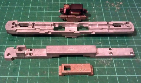
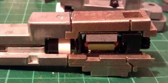
Now the top section was complete I could position and glue in the motor section.  You may have noticed I left the top and bottom sections of the chassis bolted together throughout most of this.  I did this to help ensure everything was in the correct place, particularly when it came to fitting the motor section.  As it happened I did cut the lower front chassis section a bit short and if I had glued the whole bottom section together tightly it would have been too short.  However as the chassis parts were bolted it all worked out well and below is the chassis glued together.

C-855 Chassis Build 13

Next I refitted the trucks and other internal parts ensuring there werre no metal fillings in any of the moving parts. I lubricated the motor, gears and drive shaft bearings and also put a strip of Kapton tape over the top motor brush connector.  It was ever-so-slightly touching the metal of the chassis extender and, as I proved in my prevision post, these stainless steel parts conduct electricity very well.  If this locomotive was going to be run as a DC locomotive this would be great but it will be DCC so I needed to isolate the motor.

Although the chassis extenders are great conductors the fact that I used superglue for the joints helped to form a perfect electrical barrier, so to ensure I get the benefit of all the power pickups, I bridged the chassis extenders using the original bolts, as you can see below.

C-855 Chassis Build 14

The two nearside bolts are in plastic sleeves so they don’t touch the top section of the chassis but conduct power from the bottom section.  The bottom section is connected to the right hand rail and the top is connected to the left.  To complete the test I also fitted a DCC decoder and the lighting and function wires are simply taped to the chassis for later use.

C-855 Chassis Build 15

The longer mechanism had no problem navigating some S bends and small radius turnouts on my switching layout.  I will also do a few tests on a bigger layout this week with a train in tow to see how it performs and I will share a video of that with you.

Below you can see some side by side comparisons between an original Con-Cor U50 chassis and my extended C-855 one.  The original chassis weighs 170g (5.99 ounces) and the extended one weighs 186g (6.56 ounces).  The C-855 did have 500 more horsepower than the U50 so this extra weight will help with traction.

C-855 Chassis Build 16 C-855 Chassis Build 17

I have now made some modifications to the chassis extension 3D model drawing to fix the issue I had with the first build. I will do one more test print before I make them available,, just to confirm that everything will fit together without modification.

The next step for the C-855 is to finish the 3D model for the shell and brass Additions.  Once I get them drawn up and ordered from the printer and etcher I will share them with you.

Etched Brass Name Plates

As well as all the American Railroad modeling I do I also like the British outline trains and through my local clubs and societies I get to see many from across the country.  In this post I will share with you how a British Hornby Ready-to-Run locomotive was renumbered and more importantly renamed using etched brass.

British steam locomotives, particularly the express locomotives, are usually named as well as numbered.  So are many of the smaller and industrial locomotives.  Some are considerably more famous than others around the world, such as the Flying Scotsman and Mallard, but most are simply named in groups depending on their class.  The locomotives often changed numbers when companies merged or the railways were nationalised but the names were always kept the same, giving personalities to the locomotives.

My local model railway club, the Poole & District Model Railway Society, is on the South coast of England and the primary railway here in steam days was the Southern Railway.  Naturally there are a lot of Southern Railway fans at the club and one member asked if it was possible to change the name and number on one of his SR Schools class locomotives.

The Schools class, or properly named SR V class, locomotive is a large 4-4-0 Atlantic designed by Richard Maunsell.  This class was Europe’s most powerful 4-4-0 and the last locomotive to be designed in Britain with a 4-4-0 wheel arrangement.  A total of 40 were built between 1930 and 1935 and they were all named after English public schools.  Below is a photo of ‘Cheltenham’ No. 925 restored and part of the National Railway Collection.  You can read more about it here.

SR 4-4-0 V Schools Class No 925 Cheltenham

The particular locomotive which my fellow modeller asked me to alter was a OO gauge Hornby model of ‘Shrewsbury’ No. 921. Hornby released this model under a few different names and a few other companies have made replacement name plates for some of the others but the one elusive name was ‘King’s-Wimbledon’ No. 931. And this was the name he wanted.

So to start I measured the existing locomotive name plate as you can see below to get a scale and size for the new one.

New Name Plate 1

The original name plate on the model was a flat paper with a sticky back and was easily removed.  Next I had to find an image of the original ‘King’s-Wimbledon’ name plate and luckily there were a few on the internet.  Here is a link to an image on Flicker taken by Jonathan Wilcox of the name plate hanging at Kidderminster Railway Museum.  Sadly the original ‘King’s-Wimbledon’ locomotive was scrapped; only three of the forty survived into preservation.

Knowing the required size and having information from the original I was able to layout the new name plate in CAD over the photo of the model.

Kings' Wimbledon Cad 1

Then I could create a template for the fret etch.  The original had the words ‘Schools Class’ in the small box under the main name but even in OO Gauge that would be too small so I omitted that detail.

Kings' Wimbledon Cad 2

The fret was then added to a much larger sheet with other etched parts which I needed and sent to the etcher.  Below is an image of the actual finished etch.

New Name Plate

The real name plates are brass and only the sunken parts are painted, the border and letters are clean so they can be polished.  To achieve this the whole etch is sprayed red then the top surface is lightly wiped clean leaving only the sunken areas painted.  The new name plate is then glued to the locomotive.

New Name Plate 3

The locomotive number also needed to be changed and this was done using wet slide decals.  Although only the middle number needed changing it is often easier to change all three as sometimes the font or size of the new decals can be slightly different to the model manufactures.

New Name Plate 4

I think the overall effect looks really nice and I prefer the name plate with the proper sunken areas as opposed to being just flat.  Hopefully I will be seeing ‘King’s-Wimbledon’ pulling an express train on the club layout soon.

New Name Plate 2

I have a few spare sets of the ‘King’s-Wimbledon’ name plate available should anybody want to purchase one for their OO Gauge Schools class and they can be supplied plain or painted ready to fit.  Also, if you have another name or number plate for a locomotive that you can’t find and want to get etched in any scale, please contact me for a price.

Removing Acrylic paint From 3D Printed Models

Last week I was asked by a customer if it was possible to remove or strip acrylic paint from a 3D printed model.  Knowing that some 3D printed plastics can be sensitive to chemicals this was not something that I had attempted but decided it was time I found out.  In this post I will share with you what works.

You may be wondering why you would want to strip the paint?  Well, there are several reasons but two of the most common are splattering caused by blockages in an air brush and paint being too thickly applied.  Both can ruin the finish of a model.

With injection molded parts the paint can be removed with 91% alcohol or certain paint thinners.  However even some of the stronger ones can remove detail from plastic parts.  With 3D printed parts, particularly stuff printed in Shapeways’ Frosted Detail materials, these chemicals can have a disastrous effect as they react with the material causing it to melt or break up.

After doing some research I found a product called Dettol here in the UK which can safely be used to strip acrylic paint.  Dettol, as pictured below, is a low price cleaner and disinfectant which can be watered down for cleaning tiled floors and work surfaces as well as cleaning minor cuts.

Dettol Paint Remover 7
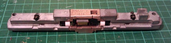
The primary chemical is chloroxylenol (C8H9ClO); the rest is pine oil, isopropanol, castor oil, soap and water.

In order to test this product I need something 3D printed which had been painted, and something that I would not be upset about if it turned in to a blob of plastic and paint.  For over a year I have had one of my Yosemite Valley Railroad Log Cars sat on the work bench in a half-painted state.  This car had been dropped and some of the detail parts had broken off so it was not high on my priority list.  As you can see below it had received a total covering of the primary paint.  The paint was an acrylic made by Revell.

Dettol Paint Remover 2

Dettol Paint Remover 1

As this is only a small model I found a small jar, filled it with Dettol and popped the car in.

Dettol Paint Remover 8

Having read all sorts of suggestions about how long to leave the model in the Dettol I decided to be on the cautious side and only left it for two hours.  I removed the car and already the paint was coming off on my fingers.  I ran the model under the tap and gently rubbed the flat areas with my fingers and they almost went back to white.

Dettol Paint Remover 11

For the underside with all the lumps and bumps I used a tooth-brush to gently scrub and this worked a treat.

Dettol Paint Remover 10

At this point I stopped. I could have removed every last bit but I was simply trying to find a method that works.  There is a drawback to doing this.  The Dettol does have a temporary effect on the 3D printed parts.  The car went very soft and pliable; it was very similar to when I heated this material with hot water to remove a bow. You can read more about that here.  This softening did not last and once the part had dried it began to stiffen again.  I don’t believe that it will remove any of the detail from the parts but if handled roughly in this pliable state the parts can easily be broken or torn if they are particularly thin.  I left the car overnight and the next day it was back to being a hard model and was ready to receive paint, although there was a smell that took me back to falling over in the playground!

So if you reach the stage with your 3D printed model that there is nothing you can do to cover a bad paint job all is not lost and you don’t have to order a new shell.  However I would still advise caution before dipping all your models in baths of Dettol; make sure you have a set down area ready for when the parts come out to reduce the risk of damage and avoid keeping the parts submerged any longer than necessary.

On another note should you wish to buy another 3D printed model, or even order your first 3D printed model, Shapeways are offering free shipping on any order untill the 12th of July 2015. Simply add your items to the cart and the free shipping discount is applied.

Adding Lights to a HO Scale Union Pacific Water Tender Part 3

In last week’s post I shared with you my work on adding working headlights to a set of my HO UP tenders; you can find the post here.  For this week’s post I will share with you how I completed the project.

Having already constructed the power pickup assemblys and installed the DCC decoders the last thing to do was to install the headlights.  For this I used headlights from a Bachmann 2-8-4 Berkshire locomotive. These, when in stock, can be obtained from Bachmann as spare parts.  They come as part of the smoke box door assembly as shown below.

HO Tender Headight 1

The headlamp is an injection molded part with a clear plastic lens that fills the headlight and runs out the back as shown below.   The lens tail has been painted black to prevent light from spilling out sideways.  With the 2-8-4 locomotive the light is inside the boiler and travels through the lens tail to the headlamp.  I intend to do the same thing.

HO Tender Headight 2

First I need to spray the plastic part with UP Harbour Mist Gray; I removed the lens to do this.HO Tender Headight 3

As I mentioned in last week’s post; I didn’t want to install the headlights untill all painting and decal work was complete.  This has now been done and the tenders are ready for their headlights.  The lamp assembly consists of the parts as shown below; the lighthouse LED with its resistor, a joiner and the headlight.  For the joiner I have used a section of plastic insulation cut from a mains electrical cable.  The inside diameter is the same as the LED and headlight lens tail so they all push fit together well.  With the parts assembled I painted the visible bits of the LED with black paint to minimise and light from inside the tender.

HO Tender Headight 4

A hole in the shell needs to be drilled just above the headlight support bracket for the lens tail to stick though; then the headlight can be glued in place.

HO Tender Headight 5 HO Tender Headight 6

Fitting the LED & joiner to the back of the lens tail inside the tender was a bit awkward to do as my hand fills the avalable space.  This also made it impossible to photograph.  However I achieved it by powering up the LED, which not only checked to make sure it was pointing straight through the joiner but also helped me see what I was doing.  Once it was aligned I pushed the joiner over the lens tail and glued the whole assembly to the roof of the tender.  Then the tenders could be fitted to the chassis and a test of the headlights could be done.

HO Tender Headight 7

Both headlights are bright but with a warm glow.  On DCC power they could be turned on and off with the F1 function.  And with a flick of the switch on the underside of the chassis they become DC powered and function like ordinary directional headlights.

The final stage was to add the rest of the details such as the roof top tool boxes and ladders.

HO Tender Headight 8

These tenders also need coupling to be completed and then they will be ready for service.

The Backmann headlights worked well but I would prefer to develop my own for use on other projects.  Having the lens carry the light from inside the tender seems to be a good idea for this so I will experiment with 3D printing the headlight and running a fiber optic cable from the back into the tender for the next set.  I will share this with you when when its done.

Adding Lights to a HO Scale Union Pacific Water Tender Part 2

Two weeks ago I shared with you the first part of this post about adding working lights to some of my HO Scale Union Pacific excursion train water tenders.  You can find the post here.  In this week’s post I will share with you the next step.

At the end of the previous post I had gotten as far as adding the power pickups to the 3D printed trucks and installing the DCC decoder as you can see in the image below.

HO UP Tender Power Pickup 17

The original idea was to simply hook the white and blue wires up to an LED which was mounted inside the tender shell.  Below you can see the chassis with the LED fitted and working.  I have also added some weight to the chassis which greatly improves the power pickup.  The weight is off-center to avoid the baffle in the center of the tender shell.

HO UP Tender Chassis Switch 7

However upon testing the system I discovered a small problem.  Because the DCC decoder I had selected is a function only decoder, that is to say it has no motor controls, it works well when run on a DCC layout but will not function properly on a DC layout.  This is because a function only decoder doesn’t recognise direction.  A regular DCC decoder will recognise forwards and backwards, switching on the relevant wires to turn on the correct lights.  A function only decoder will simply respond to function key commands.  In the case of the Digitrax TL1 that I have used; F1 will turn the white wire on and off.  When the tender is running on a DCC layout the operator can consist the tender with the locomotive, then when they push the F1 button the tender headlight will come on as required.  But under DC control the headlight will only continue to do whatever the last command was under DCC control.  For example if the light was lit when running on DCC, the light will remain lit in DC irrelevant of direction and cannot be turned off.

As these two tenders are wanted for both DC and DCC operation I will need to come up with another solution.  One option would be to replace the function only decoder with a full motor decoder.  That way it would respond to directional control in both DC and DCC but there would still be the risk of it being removed from the DCC layout with the light off, then it would not work on the DC layout.  Also full motor decoders are more expensive.  A simpler option that I have decided to use is to add a switch to the underside of the tender chassis which will allow the operator to switch the tender from DCC to DC control.  That way the function decoders that have already be purchased will not be wasted.

The type of switch required is a double pole double throw toggle switch.  Double pole means that it can switch two separate wires at the same time; in this case positive and negative.  Double throw means rather than simply on and off it switches each pole from one input to another; in this case DCC power to DC power.

As I described in part one of this post each truck picks up power from a different rail.  Irrelevant to whether it is a DCC or DC layout, one rail is treated as positive and one as negative.  At this point the two power wires need to be divided so that power goes to the DCC decoder and to one side of the switch.  The output from the DCC decoder will then go to the other side of the switch.  From the middle of the switch will come the two wires that feed the LED.  When the switch is set to the DCC side the system will operate as it did before, responding to the F1 command on a DCC system.  With the switch set to the DC side the power will bypass the DCC decoder and go directly into the LED.  Because and LED is a diode, which means power can only pass through in one direction, the light will only come on when the train is moving in the direction the light is facing.

To find the right DPDT toggle switch I had to look at the available space on the chassis.  Although there is a lot of room inside the tender itself, there is not a lot under the chassis and I did not want something huge sticking out that looked unsightly or might foul things like turnouts or crossings.  A standard DPDT toggle switche would be simply too big, as would a sub miniature one; but an ultra miniature one would work well.  Below is an ultra miniature switch next to a miniature one.

DPDT Swiches

The switch will be mounted to one side near the center of the chassis.  That way there is no chance of it interfering with the swing of the trucks.

HO UP Tender Chassis Switch 1

Although this switch is very small the lever that projects out is still too long so I cut about two-thirds of this off with a disc cutting tool and filed the edges to remove any sharp bits. It is now fairly inconspicuous under the chassis.

HO UP Tender Chassis Switch 2

A small corner of the air tank also had to be cut off to allow the toggle switch nut to be fitted but this will not be visible when the tender is on the track.  The switch will also be painted gray to match the chassis helping it blend in.

HO UP Tender Chassis Switch 8

Next the switch needs to be wired up.  The red and black wires from the trucks go to the two terminals on the far side.  The DCC decoder is then also connected to the same terminals.  This is where the power is split.  The output from the DCC decoder, the white and blue wires, are connected to the near side terminals.  With DCC decoders the blue wire is the common function wire which is positive. Therefore it needs to be connected to the switch on the same side or pole as the red wire.  If the light was powered by a regular bulb this would not make a difference but because LEDs are diodes the polarity of the wires is important.

HO UP Tender Chassis Switch 3

Next the LED wires are connected to the two center terminals as shown below.

HO UP Tender Chassis Switch 4

Often DPDT toggle switches have three positions, the middle being off.  This can be useful as it ensures there is no chance of a short as the switch is thrown. However the ultra miniature switches only have two positions but as the tender needs to be removed from the track to throw the switch this is not a problem.

The LED I am using is a 2mm lighthouse style with a warm white color.  Regular white LEDs are often too bright and give a very cold light.  I should also point out that it is necessary to use a resistor with every LED otherwise they will draw too much power and blow immediately.  Below is a comparison between an ordinary 5mm LED and the 2mm lighthouse LED.

HO UP Tender Chassis Switch LED

The light these warm white LEDs give off is perfect for recreating locomotive headlights as you can see from the images below.  For these photos the headlight has not been properly secured so it is pointing up a bit.  I need to finish the shell and add all the decals before I can fix the headlight on properly.

HO UP Tender Chassis Switch 6

Taking photographs in the dark is not the easiest thing to do but below is a shot of the tender in low light, as you can see the headlight gives a nice beam.

HO UP Tender Chassis Switch 5

In next week’s post I will share with you the final stage of fitting the LED into the shell.  I will have also finished the shells, completing the tenders.