An Alco C-855 for N Scale

In this weeks post I will share with you the first N Scale 3D printed Alco C-855 and all the accompanied parts.  If you want to read more about the history of this project click here and it will open a new page listing all my posts about it.

This model has been in the pipeline for a few years, so as you can imagine, I was very excited when last week the first test print arrived from Shapeways, and I must say I am very pleased with it.  Below you can see all the parts as Shapeways delivered them.

Alco C-855 First Print 1

At the back is the main shell; all in one piece.  The eight parts in front and to the left are the sand boxes, which fix onto the sides.  Each sand box has a locating peg which fixes into a hole on the side of the shell.  Next to the sand boxes are the crew and control consoles for the cab interior.  Below the two crew is a square plug which acts as a screw mount for holding the fuel tank on.  Next to the crew are the horns, these again have a simple peg which fixes into a hole in the shell.  The fuel tank is next to the horns and the two round parts are the drive shaft extenders.  The final two parts at the bottom are the 3D printed stainless steel chassis extenders.  The plastic parts have been printed in Shapeways’ Frosted Ultra Detail.  Although the Frosted Extreme Detail has a smaller layer thickness than FUD giving an even better finish, this was a test print and I wanted to see how it would come out before going to the best quality.  But even in FUD the details are clear and smooth and I will be very happy with this as an actual model.  Here are some close-ups of some of the detail

Alco C-855 First Print 2 Alco C-855 First Print 3

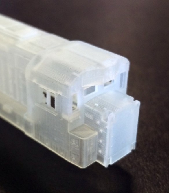
As normal with parts printed in FUD or FXD they need to be cleaned to remove the waxy residue, so after a rinse of in warm soapy water they spent 24 hours submerged in Goo Gone.

While the parts where getting cleaned I prepared another chassis.  I already had one extended chassis but as I have made some improvements to the chassis extenders I wanted to make up another.  As I have already covered this procedure in a previous post, which can be found here, I will only show the differences today.  I will be making a downloadable PDF available with full instructions soon.

As before I started with a standard Con-Cor U50/Turbine chassis.

Alco C-855 First Print 4

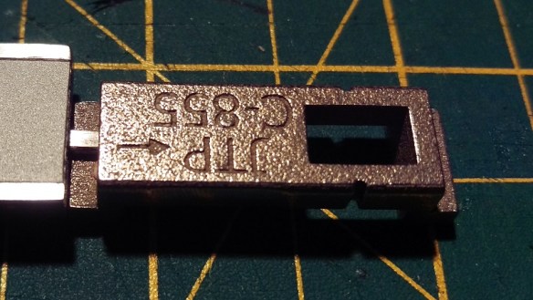
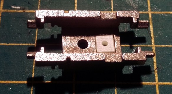
The new  chassis extenders have been tweaked in several places but the most obvious is the introduction of a forward arrow on both parts, this should help with orientation in the chassis.

Alco C-855 First Print 5 Alco C-855 First Print 6

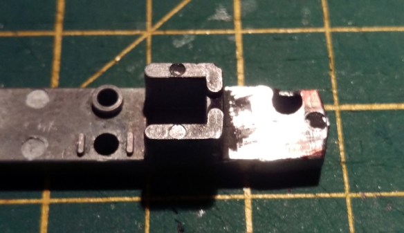
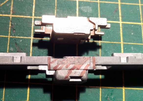
The top section should be done first.  And this simply means removed the section highlighted below.  I used a cutting disc in a Dremel type tool.

Alco C-855 First Print 7The three parts where then glued together.  The key is to make sure the dog leg part of the chassis extender is flush with the underside of the remaining parts.  There should be a small gap at the location where you made the cut.  That way the chassis will be the correct length and it will be easer to keep it square.

Alco C-855 First Print 8

Unlike last time, I also need to make some cuts at the front because the body of the locomotive is narrow below of the cab.  The two wings need to be cut off as shown below.

Alco C-855 First Print 9

Also two notches need to be made.  I will give the sizes of these in the downloadable PDF.  The top notch ended up a bit larger than I had hoped because of the screw hole.  You could simply cut it all off but I want to keep as much weight as possible.

Alco C-855 First Print 10

As I pointed out earlier there is a plastic square plug used to screw in the fuel tank.

Alco C-855 First Print 11

This simply fits into the square hole in the bottom chassis extender.

Alco C-855 First Print 12

It will be held in by the motor and when you screw on the fuel tank, using the same screw from the U50/Turbine fuel tank, it will pull tight.

Alco C-855 First Print 13

With the bottom chassis section it is important to cut it as close to the parts that hang down as possible.  Other wise you may end up with a gap in the chassis frame. Indicated below is the section to be removed.

Alco C-855 First Print 14

Once fully assembled it should look like this.

Alco C-855 First Print 15

My C-855s will be DCC so I have installed a decoder in the space at the rear of the locomotive.

Alco C-855 First Print 16

The next step was to test fit the shell.  In the photo above you can see a square hole at the front of the fuel tank.  Inside the shell is a tapered peg so as the shell slides onto the chassis the shell will spread untill the peg pops into the hole holding it tight.

Alco C-855 First Print 17

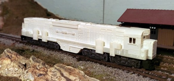
The shell is nice fit and once the pegs locate into the fuel tank you can comfortably pick it up by the shell and it wont fall apart.

One of the identifying details on the C-855 is the large sand boxes on the side and because of the locating pegs these can easily be clipped into place.  I have made them a separate part to make it easer to paint the model.  In the photo below they are not glued in place but simple press fitted.

Alco C-855 First Print 18

But as great as the loco now looks there are still lots of parts missing.  And today I took delivery of the first batch of etched brass Additions for this loco.

Alco C-855 First Print 19

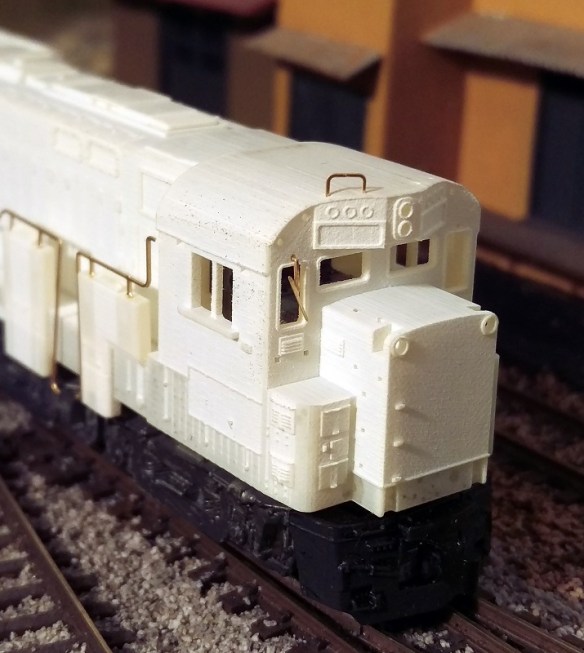
As I am going to paint the loco a lot of the parts are not ready to go on yet, plus I only got them today, but to give you and idea of what the finished loco will look like here are some picture with some of the brass Additions loosely fitted.

Alco C-855 First Print 20

Because just about all the brass Additions have mounting holes or slots they should be very easy to install.  The handrails drop into the top of the sand boxes which makes them easy to align.  There are a lot more parts to be added and some, like the ladders, can’t be shown yet as the handrails need to be fixed properly first but as you can see from the image below even the windscreen wipers have mounting holes.  It has swung to its natural hanging position but once glued in, it will line up with the left of the window frame.

Alco C-855 First Print 21

I want to do a few checks to make sure everything is where it should be for all the brass Additions and then the shell will be made available on Shapeways. I think that will happen in the next few days.  The chassis extenders are available now and can be ordered in sets of one, two or three by clicking on the links below.

Set of one C-855 chassis extenders.

Set of two C-855 chassis extenders.

Set of three C-855 chassis extenders.

There is an option to print the chassis extenders in WS&F and FUD which are both cheaper than the stainless steel but you will lose a lot of weight and please note: I have not tested them in these materials.

Although I normally post on a Monday I will do an extra post this week to let you know when the C-855 body and parts are ready as I know several of you are keen to get them.  If you order the chassis extenders now you can add the shell to your order at Shapeways without paying for shipping twice, as long as you do it in good time.  I also have brass Additions in stock, these are £6 GBP each.  Please contact me though contact page or email me if you would like to order some.

The next step, apart from painting and finishing the C-855, is to finish drawing the C-855B.  The chassis will be exactly the same so the extenders will be need for that too.  I will also be drawing a dummy chassis for both locos and will be sharing that with you soon.

Drawing an Alco C-855 for N Scale Part 5

If you have been following my blog for a while you will know that I have been working on an N Scale Alco C-855.  You can read the first part here.  In this week”s post I will share with you what I have done to finish the A unit and get it ready to order a test print.

In my last post about the C-855 I showed you the first print of the metal chassis extenders and how I fitted them into the Con-Cor Turbine/U50 chassis.

C-855 Chassis Build 15

This chassis runs well, and pulls even more than in its original counterpart; probably due to the increased weight.  However there were a few issues with the print so I have improved the 3D model to rectify them.  In the image below you can see both parts from the top and bottom.

Alco C-855 Chassis Extenders mk2 (render)

The space for the motor has been widened by a fraction as the motor was a tight fit in the first print.  The wire channel has also been increased in size so the motor wire is a better fit.  I have also made some changes to the bottom of the lower section.  The arrows point forward on both parts to help with orientation when assembling the chassis.  There is now a rectangular nub that sticks out to locate the fuel tank on the bottom of the locomotive.  Also a square hole has been added which has been designed to take a 3D printed screw fixing which is used to hold on the fuel tank.  The exploded view below shows how these fit together.

Alco C-855 Fuel Tank Fitting 1 (render)

I have designed this assembly so the original Con-Cor turbine/U50 screw can be used athough any similar size screw will work.

Alco C-855 Fuel Tank Fitting 2 (render)

This section of the fuel tank is only the bottom as the sides are part of the main body.  Looking at the image above you can see a square hole in the side of the fuel tank, this is designed to receive a nub sticking out from the shell. You can see the nub in the image below which shows half of the shell.  As the bottom of the fuel tank is fixed with the screw it becomes a solid fixing for the shell.

Alco C-855 In Side Shell (Render)

As with a lot of ready-to-run locomotives, to remove the shell it can simply be spread in the middle and lifted off.

To make painting and adding decals to this model easier the four large sand boxes on the sides have been made as separate parts.  The rear six are the same but the front pair are longer as they have to step over parts of the chassis.  The shell has slotted fixings in the side of the running board to receive the sand boxes so they can be securely fitted.  The holes on the tops are handrail fixings.

Alco C-855 Sandboxes (render)

As with my DT6-6-2000 and RT-624 locomotives my C-855 will come with crew for the cab, Bert and Ernie.  The controls on the console are very basic but this is N scale so once they are inside the cab it will be hard to see anyway.

Alco C-855 Crew (Render)

Because of the shape of the chassis, there is a large chunk of metal sticking up into the cab, the crew had to be pushed to the sides.  There are locator pockets in the shell walls to receive the crew once they have been painted.  As the C-855s ran in an A-B-A configuration you may not want crew in the rear A unit so they can simply be left out.

Below you can see the crew in their place with half the shell removed.

Alco C-855 Inside cab (Render)

This view also shows you the headlight fitting in the roof of the cab.  The shell has been shaped to receive a standard 3v 2mm LED.  A nice warm white LED can be fitted directly into the roof of the cab and a pair of headlights will shine from the front.  This area will need to be painted black on the inside to prevent the light from shining through the shell.

Even the horn is a separate 3D printed part; this is both to make it easer to paint and to protect it from being knocked off in shipping.  Below you can see all the 3D printed plastic parts for one C-855.  The large gears are the drive shaft extenders which are needed when the chassis is extended.

Alco C-855 3D printed parts (render)

In the cab you can see lots of holes; this is because all the grab irons and handrails plus many other details are brass parts that will be supplied in a brass Additions set. The set will also include some of the metal walkways, windscreen wipers, side ladders, MU hoses and sun visors for the cab.

So putting this all together, this is how the N Scale C-855 will look.  Please note the trucks under the 3D model are not yet correct.

The end will have brass grab irons up the center and walkways over the air intakes.

Alco C-855 end (render)

The cab with all of its brass parts will be well detailed

Alco C-855 666.Front (render)

Overall this monster of a locomotive has an imposing presence.

Alco C-855 (Render)

The next step is to finish the drawings for the B unit and design a dummy chassis so an A-B-A set can be made without powering all the units, if required.

The new 3D printed metal parts as well as the 3D printed plastic parts for the C-855 have new been sent for test printing so I should have the first N Scale C-855 within the next few weeks.  Once it arrives and I have cleaned up all the parts I will share some images with you.

Completing My N Scale DD35 Set

This week’s post is about completing my set of Union Pacific EMD DD35 locomotives and making one of them look like it’s about ready for the scrap man’s torch.

My N Scale DD35 kit comes with 3D printed handrails and although they are strong and fit well, they are a bit on the thick side, as you can see in the image below.  This is one of my early DD35 dummy locomotives.

UP DD35 With 3D Printed Handrails

When running a DD35 along with a Con-Cor U50, as shown in the next image, this is less of a problem as the U50 also has oversized handrails so they work well together.

DD35s and U50

To further improve the DD35 I released an Additions kit of brass handrails and as you can see below they greatly improve the locomotive.

UP DD35 With Brass Handrails

The DD35 above has been painted as if it was a new locomotive and is ideal for running with a pair of GP35s as shown in the following image.

UP DD35 with GP35s Brass Handrails

Ideally another DD35 is needed to complete the set but as you can see from the image below the 3D printed handrails tend to stand out.

UP DD35s with GP35s Plasic & Brass Handrails

Weathering a locomotive always improves the appearance, even if it’s a little soot around the exhaust stack and grills, but to really make a DD35 look like it’s had a hard life you need to go a step further.

The DD35 shell used for the locomotive below was actually a damaged shell.  It had suffered damage which had left the surface very rough and some of the detail had been obliterated.  This made the shell perfect for a heavy weather.

UP DD35 With Brass Handrails & Heavy Weather 1 UP DD35 With Brass Handrails & Heavy Weather 2

Not only has the paint been darkened and discolored but rust streaks have been added along the sides; this has been done with decals.

UP DD35 With Brass Handrails & Heavy Weather 3

Very close up you can still see the roughness of the shell but you have to look for it.  Overall the effect of all the rust and corrosion blends in with the roughness to create a great-looking loco.

UP DD35 With Brass Handrails & Heavy Weather 4

Putting all three DD35s together you can see the differences.

All UP DD35s

I am planning on running both the heavily weathered and clean DD35s together as if one has been refurbished.

UP DD35s Brass Handrails Heavy Weather & New

Although it’s difficult to see, my GP35s are not actually the same.  One is a Phase 2 and a later model so I have one new and old GP35 and one new and old DD35 to complete my set.

UP DD35s & GP35s Brass Handrails Heavy Weather & New 1

My older GP35 Phase 1, on the left, will get some heavy weathering too.  This line up would have produced 15,0000 horse power at the draw bar and even for the long trains we run on our N Scale layout, Solent Summit, that’s a lot.  So only the weathered DD35 is powered and the refurbished one is a dummy locomotive.

All the painting and weathering on these DD35 locomotives was done by Bob Norris who has also painted and decaled Southern Pacific DD35 locomotives.

SP DD35 9902 8

In fact we can offer DD35 locomotives in SP, UP & EMD Demonstrator liveries.

DD35 UP SP Demonstrator

If you wish to read more about my DD35 kit for powered and un-powered models here is a link to their page in the shop and here is a link to their gallery page.  If you are interested in getting a ready-to-run model in any livery, in new or weathered condition, please contact me though the contact page.

Making Talus and Rock Fall for Your Layout

As you may have read in my previous posts I am currently building a pair of modules to form part of the Gosport American Model Railroad Group’s N Scale Layout.  In this post I will share with you a quick and cheap method to make some talus, boulders and general rock debris.

You can buy bags of talus form companies like Woodland Scenics in a variety of sizes but sometimes having a larger variety can be useful.  If, like me, you have cast your own rocks from rock molds (you can read more about doing this here) then it’s likely you have lots of bits of plaster left over.  I tend to fill up my rubber rock molds and this causes plaster to flow over the flat rubber and mold sides.  When I break out the rocks these pieces break off and I collect them in a tray.

Depending on what you want to use your talus or rock debris for will depend on how you color them, but for me I want to simulate fallen rock into my canyon and rock that has been washed down the river in the winter floods.  From reference materiel I have noticed that there is often less difference in the color range of the talus than in the actual rock faces.  This might be because only certain parts of the rock face are crumbling due to the different rock composition so only the softer rock will be in the bottom of the canyon.   Given that my dominant rock colors in the canyon are yellow ocher and burnt umber my talus will be a blend of these two colors.  You can read about my rock painting process here.

So here is my recipe for rock soup!  I start with a tray of plaster bits and crunch them up with my hands until they are roughly the right size.  Then I pour on a bit of burnt umber that has been mixed with water at a ratio of 1 part pigment to 16 parts water.  I give the mixture a stir to move the parts around.

Making Talus 1

The pigment soaks right into the dry plaster parts as you can see in the above photo.  Because I didn’t add a lot of pigment it only soaked into certain faces in a similar way to the leopard spotting I used on my rocks.  Next I add yellow ocher mixed at the same ratio 1 part pigment to 16 parts water.  This time I added a lot more pigment so all the bits get a good soaking, hence the term ‘rock soup’.

Making Talus 2

The rocks in the tray are stirred and shaken up so all surfaces get a good coating and the mixture is left for an hour or so to ensure the rocks get thoroughly saturated.  That way if they are chipped or broken they won’t show through brilliant white.  Once I am happy with the amount of saturation I drain off any excess liquid and leave the rock parts to dry.  This may take a day or so and it is a good idea to give them a stir now and again which will bring the wetter bits to the surface helping them to dry faster.  This processes will also work on Woodland Scenics’ talus as you can see below.  The lower tray is all the plaster debris and is a lighter color because it is a more porous material than the Woodland Scenics’ talus.  However the two will mix together well.

Making Talus 3

The area I am going to be using this on is the bottom of my canyon which you can see in the pictures below.

Making Talus 5

Making Talus 4 Making Talus 6

The river bed has been painted and is ready for some debris.  I start by dropping some of the mixture down the rock faces to see where it lands, also I add clumps in areas that would have caught rocks when the water was flowing at full strength in the winter months.  All the modules on the GAMRG’s layout are set in late summer so the water level will be low.

Making Talus 7 Making Talus 8

Next I use a watered down PVA glue in a spray or mister.  Again Woodland Scenics sell the right glue for this called Scenic Cement but you can make your own.  They also sell the spray bottle but I tend to use a basic one with a removable nozzle purchased from a garden center designed for misting plants.  It is a good idea to have a bowl of water close by so you can put the nozzle in to soak between spraying as it will start to clog up.  Because the mister gently soaks the areas it doesn’t move the rocks about.  I tend to place the talus is several stages giving the area a good soaking of scenic cement between each layer.

Making Talus 9

As you can see below I do mean a good soaking.  The talus is heavier than scenic scatter material and you don’t want it coming off the layout, especially a modular one that will get bumped around between shows.

Making Talus 10

You don’t have to wait for the first layer to dry before adding the next, in fact it is best not to as the new layer will sink into the wet glue adding to the strength.

Making Talus 11

Once you are happy with the amount and overall look give the whole area another good soak with glue and leave it overnight to dry.  Don’t be tempted to touch it until it’s dry as the talus will be very easy to dislodge until the glue has totally set.

Once all the glue has dried it will become clear and leave you with a solid scene that you can add water to or simply leave as is.

Making Talus 14 Making Talus 15 Making Talus 16 Making Talus 17

Making Talus 18

I still need to add some more vegetation at the river edge and add the water itself which I will share with you in another post.

This coming weekend, the 3rd and 4 th of October 2015 I will be at the Fareham RailEX model railway show with part of the GAMRG’s N Scale layout.  The exhibition will be at the Fareham Leisure Centre, Park Ln, Fareham, Hampshire PO16 7JU, UK and you can read more about the show here.

My new modules that I am working on will not be in this show as they still need a bit of work but it would still be nice to see if you are in the area.

Quick & Easy Ways to Ballast Track

Over the years I have tried all sorts of methods to ballast track.  Some have been very time-consuming and some have just looked rubbish.  In this post I will share with you a method I have found to be fairly quick and easy and also gives good results.

Ballasting track is a key part of building a model railroad or railway.  Not only is it necessary for making the track-work look right but, just like the real thing, the ballast holds the track permanently in place.

The current layout which I’m working on is an N Scale modular layout and forms part of the Gosport American Model Railroad Groups ever-growing layout.  This particular module, New Mills,  is a small country halt next to a group set of factories.  The halt is used mostly by the factory workers and small town nearby.  Most of the trains pass without stopping so rather than platforms the tracks outside the halt have been boarded over so passengers can access to the local passenger cars via their steps.  Below is a photo of the left hand end of the module  The main line enters on the left nearest to the front.  It splits into two tracks that pass the station depot and then rejoin each other before leaving from the right hand end.  The third line with the end of a GP38 sat on it is the entrance to the factory sidings.

Balisting Track 1Before I even think about ballasting track I always do lots of running on the layout to make sure everything works okay.  The track is glued down onto a cork road bed which in turn is glued to the module top.  The cork is important for a few reasons which I will cover in a bit.  In the picture above you may have noticed that the track has been weathered.  This is not a necessity but it adds the realism I like to see; railroads are not a clean place.

I have several methods of weathering track.  First there is the spray paint method.  This can be done with an airbrush or aerosol can.  For the bulk of this module I used a grimy brown color aerosol.  Before spraying I removed everything from the module and simply sprayed along the tracks.  Then I quickly wiped the rail heads with a cloth to remove the paint.  Once the paint had dried I also ran over the rail heads with a track rubber to totally remove any paint residue.  Since doing that I have also added a few more bits of track but as I don’t want to risk spraying other stuff now fixed to the module I used a brown wash to weather the rails.

Balisting Track 2

Making a wash from paints is fairly easy but I find this the quickest.  Once the pot is shaken up the wash inside simply paints on.  I tend to roughly brush over the ties and rails then brush again with no wash on the brush.  This removes any excess wash and gives a mixed finish.  As before I wipe the rail heads over with a cloth.  Once you start to weather your track any new sections stand out as you can see in the photo below.

Balisting Track 3

Once all the track is weathered and had a chance to dry I tested it by running a few trains. Then it’s time to add some ballast.  Ballast comes in all sizes and colors.  For our group modules we stick to the same make and colour for continuity which is Woodland Scenic Fine Gray ballast.

On the real railroad the track is laid on top of a deep bed of ballast, then more is poured on top and packed or tamped down tightly around the ties.  Because the track is on a bed of ballast it is easy for the track gang to raise or lower the track to ensure smoothness as well as adding any special enhancements such as super elevations on corners.  Also this means the track is raised off the floor and the ballast acts as a natural soak away to stop water from flooding the tracks. Given most track ties were timber this was a good thing.

On the model railroad adding a bed of ballast is not very practical so we use a layer of cork.  Then when the ballast is poured on and covers the cork it will look like a nice deep bed and form the correct shoulder or slope on either side.

To start with I simply pour the ballast on in the right area trying to gauge the right amount.  Then using my finger I run it along the center of the tracks spreading the ballast evenly around.

Balisting Track 4

Then to get the right finish I use a small paint brush to carefully move the blast around.  This works for most of it but there will always be the odd bit that gets in the wrong place.

Balisting Track 5

The main area to worry about is the inside of the rail as this needs to be kept clear for the wheel flanges to run in.  I find the best tool for cleaning this is a small watchmakers screwdriver which can be run along the inside of the rails and knocks off any stray ballast.

Balisting Track 6

The area in the photo above is a little thick with ballast by intention.  Normally ballast is leveled off just below the tops of the ties and the excess is moved down the line.  However at that particular section the track is flanked at both ends by a boarded walkway and roadway so the excess ballast tends to get left there and forms a ridge down the center of the track.  On the other side of the roadway the ballast starts to get a bit thinner as the track crew have more room to spread out the ballast.

Balisting Track 7

When it comes to turnouts it’s okay to add ballasts around the rails but the gaps between the check rails and inside the frog (the V shape in the middle) must be kept clear.  Again the small screwdriver is ideal for this.  It is also important to keep the moving areas free so keep moving the turnout blades thoughout the process.

Balisting Track 8

Once the ballast is in the right place I use an old freight car with big flanges as a tester.  I run it up and down to make sure there is no ballasts where it should not be.  I also change the turnouts.  Note: if you have solenoid operated turnouts the sudden bang will dislodge the ballasts and can also bounce it into areas you don’t want it.  Although this can be useful for removing it if you have got some in the turnout blades.

Once all the turnouts can be thrown, manually, and the test car runs up and down, it’s time to stick the ballast down.  For this I’m using a product from Noch that was recommended to me.

Balisting Track 9

I have used other ballast glues and made my own in the past but this product works better than any of them.  The dispensing nozzle allows you to carefully and accurately drip or drizzle the glue where you need it and it doesn’t cause any lift in the ballast.  By ‘lift’ mean the ballast raising up onto liquid glue that has not soaked into the ballast.  It does not bubble or flow along the ballast causing washouts; it simply runs in.  In the picture below I started in the center of the track from the left, and although I was a little heavy-handed the ballast glue still soaked in anway.

Balisting Track 10

I then worked around the tracks covering all the ballast.

Balisting Track 11

Before the glue has a chance to dry I did one more test with an old freight car. This is why I use an old freight car as you get glue on the wheels. Then I left it overnight to set fully.  The next day all the ballast was dry and any surplus could be picked up with a vacuum cleaner.  Because the rail heads might have been covered in the glue I used the track rubber again to brighten them all up so I could do a proper test with a loco.

Balisting Track 12

The next step, which I still have to do, is to weather the ballast.  Out on the main line the ballast would be fairly clean but at the ends of a station area like this there would be coal, oil, grease and diesel spills where locomotives would have been stood.

BalistingTrack 13

You may also be wondering why I haven’t ballasted the track in the industrial area?  Well, this track work is under the obligation of the factory owner to maintain, not the railroad, and the ballast will be lower and dirtier, not to mention full of weeds at the ends of the tracks. To do this I need to mix up some ballast with other products and I will share that with you in a later post.

Repairing an N Scale Minitrix Steamer

The German firm Minitrix, now owned by Markin, used to produce a range of US and UK steamers as well as their native German locomotives.  Most of these early models date back to the 1970s and are still running strong.  However there are a few parts that are prone to breaking and in this post I will share with you how to repair the crank pin on a Britannia class locomotive.

Minitrix used the same chassis or a variation of the chassis on a variety of locomotives.  In the US it was the 4-6-2 K4 and 2-10-0 Decopod.  In the UK it was the 4-6-2 7P Britannia, 4-6-2 A3, 4-6-2 A4 & 2-10-0 9F class engines.  These all had metal side rods, drive rods and eccentric cranks but the eccentric pin that holds it all together is plastic.  And it’s this part that has been known to break. If you look at the model in the picture below I have circled the crank pin in red. The side rod connects all three driving wheels together and is the nearest to the wheel.  The connecting rod or main rod is fixed to the center wheel and runs into the cylinder.  The crank pin holds the connecting road and side rod to the center wheel.  The eccentric rod connects to the cranked end of the pin and drives the valve gear in the cylinder.

Minitrix Crank Pin 1

The crank pin is designed so that the side rod and connecting rod can easily rotate without binding on the pin but are also held in place. So you can see how this works I have modeled the crank pins below.  The square shaft on the end of the pin fits into the wheel.  Because it’s square this will ensure it will rotate with the wheel. The side rod and connecting rod fit over the round section and are held in place by the wheel and cranked top.  The holes in the side and connecting rods are larger than the pin to allow free moment.

N Scale Minitrix Crank pin

What normally happens is the metal rod assembly becomes jammed and the weakest point is the plastic crank pin. The pin breaks where the round section meets the square section and falls out.  The connecting rod then flails about and can become bent.  With this 4-6-2 that is exactly what has happened, although luckily the connecting rod wasn’t bent.

Minitrix Crank Pin 2

So to fix this engine the first thing needed is a new crank pin.  Spare parts for these engines ran out years ago so my next option is to 3D print one.   I printed some using the 3D model above in Shapeways Frosted Extreme Detail material.  It will also print in their Frosted Ultra Detail material.

Minitrix Crank Pin 3

Next the old square section on the crank pin needs to be removed.  For this I used a small drill in a pin vice as you can see below.  I selected a drill that was a bit smaller than the pin.  Once I had drilled through the pin the remaining materiel was so thin and weak it pulled out with a pair or tweezers.  You can see the remains of the pin under the new one.

Minitrix Crank Pin 4

In the image below you can see the old and new parts next to each other.  The old crank pin is connected to the eccentric rod by a metal pin which has a flared end and cannot easily be removed.  One option is to cut off the old plastic crank and un-flare the end of pin hoping to fit it into the new one.  However that is very hard to do.

Minitrix Crank Pin 5

To make this job easier I did cut off the old plastic crank but I did not un-flare the pin.  Instead, using a very sharp craft knife, I cut through the loop on the end of the new crank pin.  This then forms a C shape although the two ends still touch.  Carefully spreading the new C shape I was able to push it over the metal pin as you can see below.

Minitrix Crank Pin 6

The connecting road and eccentric rod were then refitted to the loco.

Minitrix Crank Pin 7

The new crank pin simply push-fits into the driving wheel, ensuring it passes through the hole in the connection and side rods.

Minitrix Crank Pin 8

It is important to make sure the crank pin is pointing in the right direction, which is towards the center of the wheel.

Minitrix Crank Pin 9 Minitrix Crank Pin 10

The next part is to test the the new assembly and what could be better than running it on a layout.  Below is short video of the engine running demonstrating that the new crank pin works perfectly.

The rocking motion is caused by the traction tires as the loco is supposed to be moving.

The last thing to do is to add some silver paint to the new crank pin to help blend it in.  It’s best to put on as little as possible as you don’t want to paint the parts together or cause a bind.

Minitrix Crank Pin 11

A pack of four replacement crank pins is available from Shapeways here.

Alternatively if you would like this repair made to your locomotive for you, you can contact me though the contact page or directly at jamestrainparts@yahoo.co.uk and we can arrange to get it done.