Replacing the Motor in A Con-Cor Turbine/U50/C-855 Chassis

The Con-Cor Turbine and U50 chassis has been around for many years and has always been a solid runner.  However, by modern standards, the motor in the chassis is rather noisy and draws a lot of current.  In this post I’ll share with you how myself and Bob Norris replaced the motor to improve these issues.

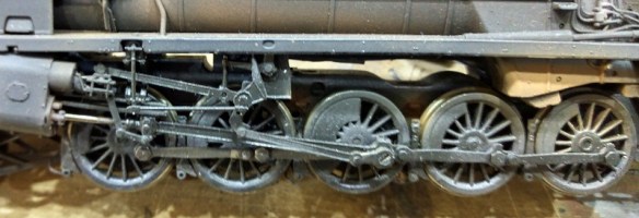
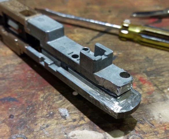
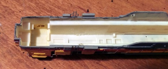
The chassis, as pictured below, has a central motor powering two drive shafts which in turn power the two outer trucks.  The inner pair is unpowered.  The design has been used for the GE U50 model since 1973, which interestingly was first made for Con-Cor by Kato.  This chassis was also used for the GE 4500 Gas Turbine model which was released in 1975.

Con-Cor GE U50-Gas Turbine Chassis

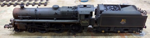
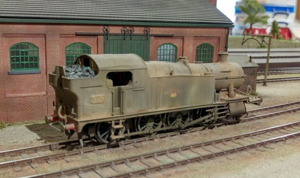
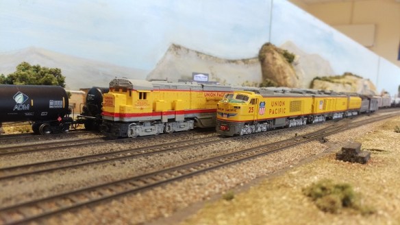
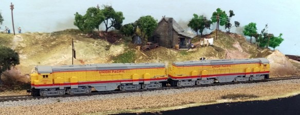
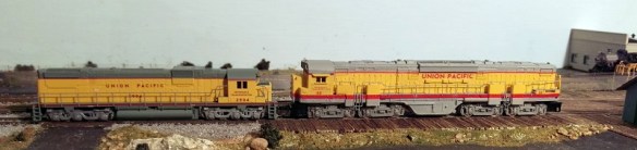
And more recently it’s been used by me for the Alco C-855 as shown below, stretched and fitted with a DCC decoder. You can read more about the stretching of the chassis here or by searching this site for C-855.

C-855 Chassis Build 15

The first three C-855s I made went to Bob Norris and the chassis have been running well but recently we have added sound decoders to them and this started giving us a few problems.  Firstly the motors are fairly noisy and secondly they draw lots of current.  When pulling a heavy train with the sound at full volume the sound decoders have been known to shut off and then start behaving erratically.  Now I know the original three ordered by Union Pacific didn’t last long as they were prone to failure but that wasn’t the aim here!

So after doing some investigating we did a stall test on one of the motors and we discovered that the peak amperage can sometimes go over the maximum for the decoder by a fair amount.  To find out what a stall test is and how to do it please see this post.

Below is a short video of a C-855, running light engine with the sound off so you can hear the motor whining.  The clicking is the Digitrax DCC controller notching up and down.

To solve the issues a new motor was found for the chassis.  Coincidently it is also made by Kato, although a much newer design. The Kato motor 420000 is advertised as a replacement motor for Atlas N Scale.  We found them on eBay though the seller Soo-Much-Stuff.

The motor comes with no gears on the drive shafts which is ideal. Below you can see the new motor on the right and the old on the left.

c-885-new-motor-1

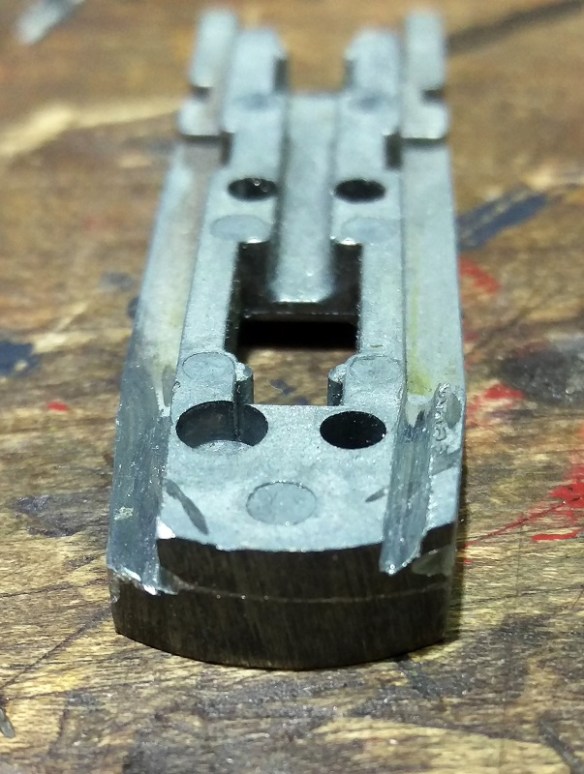
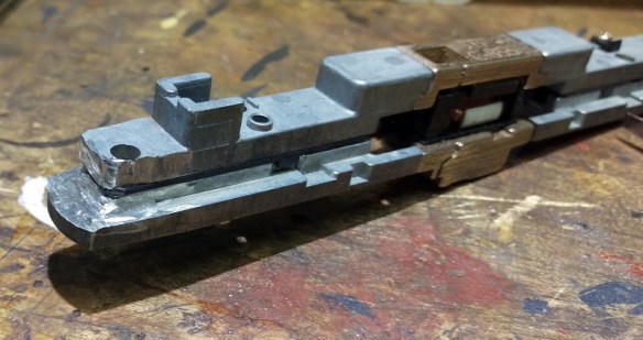
The old motor, as shown below, sat in the middle of the raised area of the chassis and the gears ran inside larger diameter cup gears.

c-885-new-motor-0

The chassis un-screws and separates easily allowing the motor, drive shaft and motor cradle to be removed.

c-885-new-motor-2

The gears on the old motor (top in the photo below) need to be removed and fitted to the new motor.  They are simply press fitted and can be removed by applying pressure behind the gear.  Not too much pressure or you will spend ages looking for the gear on the other side of the layout, don’t ask me how I know this!

c-885-new-motor-3

To fit them to the new motor the process is the same, just the other way around.

c-885-new-motor-4

The gear needs to slide on far enough so the drive shaft is almost at the other side.  Note, this was done for the C-855 extended chassis, the U50 and turbine chassis should be the same but it’s a good idea to check as you go.  If the gear slides on too far it may not make good contact with the cup gear.

c-885-new-motor-5

With the gears fitted the tabs can be bent up ready for soldering wires to.  If you are doing this for a DC locomotive the tabs will need to be in the same positions as the motor you have just taken out.

c-885-new-motor-6

The bottom tab pokes through the motor cradle.

c-885-new-motor-7

Upon test fitting we discovered the motor was sightly smaller than the original which caused it to sit a bit low. To solve this a plastic shim was made to fit in the bottom of the cradle.

c-885-new-motor-8 c-885-new-motor-9

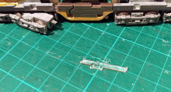
The cradle was then fitted back into the chassis ready for the motor.

c-885-new-motor-10

As you can see below the gears now fit nicely into the cup gears.  If the shim was too thick the cup gears would be lifting and this would cause noise and strain the motor.

c-885-new-motor-11

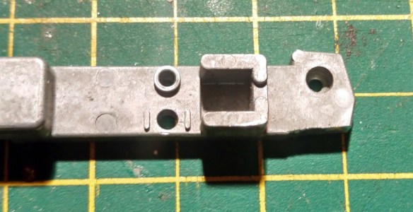
The wires can now be added to the motor.  There is a channel formed in the C-855 chassis extender on either side so you have a choice on where to run your wire.

c-885-new-motor-13

c-885-new-motor-14

The chassis is now fully reassembled and ready for testing.

c-885-new-motor-15

Below is another short video showing how quietly the new motor runs.

With all three units converted to new motors the performance should be greatly improved and hopefully I will get some video of them running soon to share with you.

Thanks go to Bob for the photos and videos of the motor swap.

The new Shapeways order has now been shipped so next week I will start showing you some of the products I’ve been sharing over the last few weeks.

The Best Way to Weather My Stock

In last weeks post I promised to share with you some of my newly-weathered stock so that is exactly what I’m going to do.

I have a range of rolling stock from different manufacturers and a lot of the freight cars,  although they are very nice, some do seem a bit brightly coloured.  To be fair a lot of them would have been this way when they rolled out of the factory for the fist time.  But after spending some time of the rails everything gets dirty,  and even rusty as they get older.

I think they should look more like this.

Weathered Stock 11

Here are some closeups shots.

Weathered Stock 6

Weathered Stock 5

The next three where identical before weathering.

Weathered Stock 4

Weathered Stock 3

Weathered Stock 1Weathered Stock 7

Weathered Stock 2 
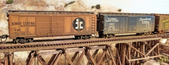
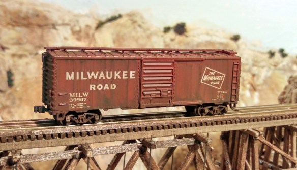
As a comparison; below is a factory weathered freight car, on the left, alongside my weathered freight cars.

Weathered Stock 8

One of the things I didn’t like about the factory weathered freight car was the trucks, they look too shiny and new compared to the rest.

Weathered Stock 9

Below is a short video showing a train passing with regular stock followed by a train with the new weathered stock.

So how did I do this?  Well given that time is precious, as those waiting for projects to be draw will appreciate, I’ve found the best solution.  Get somebody else to do it!

These were all airbrushed by Model Railway Solutions. MRS provide all sorts of modeling solutions from flat pack baseboard construction, all the way up to complete model railways built to exhibition standards.

The weathering service is very reasonable and they are happy to work with large batch projects which can reduce the shipping costs when sending models from overseas.

Here are some of the other models that were on the work bench when I collected this batch.

This is an N gauge southern region Merchant Navy class locomotive.

Weathered Stock 14 Weathered Stock 15 Weathered Stock 16

This is a OO Gauge 9F made by Hornby.

Weathered Stock 17

Although the main body is dull and dirty the running gear looks wet and oily, these photos don’t do the locomotive justice.

Weathered Stock 18

Here is a BR Standard Class 4MT made by bachmann.

Weathered Stock 19 Weathered Stock 20

I liked the rusted areas around the tender water filling area.

Weathered Stock 21

The real coal in the tender was also added by MRS.

Weathered Stock 22

Coaches also get dirty and below is a OO Gauge collett coach made by Hornby which has also had the air brush treatment.

Weathered Stock 27

And to pull a train of these coaches, what could be better than a GWR Castle class. Again this OO gauge model was made by Hornby and is now in a typical representation of what it would have looked like when these engines where nearing the end of their life. Weathered Stock 29

Of course freight engines where not looked after anywhere near as well as the passenger locos.  Below is an image of a brand new OO Gauge Hornby 2-8-0.

Hornby 2-8-0

MRS spent some time on it and now it look like this.

Weathered Stock 23 Weathered Stock 24

It still runs as smooth as silk but in this condition you can just imagine it has seen many years of use.

Weathered Stock 25

MRS are happy to be contacted by phone or email and both can be found on there website.  Alternatively you can always drop me a message through my contact page and will be happy to talk to them for you.

An Alco C-855B Chassis For N Scale

In last week’s post I said I was going to share with you the test fitting of the N Scale Alco C-855B body onto the modified chassis and that’s exactly what this week’s post will be about.

The C-855B is basically a C-855 without a cab. It’s exactly the same length and all the trucks and parts are in the same place.  However, as there is no wide cab this section at the front end of the chassis will need to be modified.

The donor chassis is from a Con-Cor U50 or Turbine and has been extended using my 3D printed stainless steel parts. You can read more about that here.

The rear of the chassis doesn’t need any modifications. The front needs to be cut to resemble the rear.

In the image below you can see the top section of the extended chassis.  I’ve also started to modify it by cutting off the front right lug which used to fit inside the cab area.

C-855B Chassis 1

In this close up you can see I’ve cut it so it tapers in very slightly from the side of the chassis.  This helps with the fit.

C-855B Chassis 2

Repeating the same cut on the left hand side will finish off the top section.  To make these cuts I simply used a cutting disc in a Dremel-style tool.

C-855B Chassis 3

The bottom section will require a bit more work.  Again you can see in the image below I’ve already done the right hand side and I am working in the left. To get the cuts in the right place I fixed the top and bottom halves of the chassis together and marked the bottom with a pencil.  The cuts should line through vertically.

C-855B Chassis 4

Using the cutting disk I cut along the top of the chassis following the same line as I did with the top section which was marked in pencil.  You only need to go down as far as the lower flat area.  Then, cutting horizontally, I came in from the side.

C-855B Chassis 5

When you are almost through it should look something like this.

C-855B Chassis 6

Once the unwanted section has been cut out the area can be cleaned with a file.

C-855B Chassis 7

The last section to remove is part of the front.   Again I marked the cut line with a pencil after fixing the two halves together and then used the cutting disk to slice in from the top.

C-855B Chassis 9

The last cut comes in horizontally to remove the unwanted section.

C-855B Chassis 10

The chassis is then assembled and is ready for a test fit.

C-855B Chassis 11

I found that my chassis was about 0.5mm too long for the shell; this might be caused by a slight shrinkage in the 3D print when it first cooled or too much glue between the chassis extenders and the original bits.  The shell should be a nice fit and shouldnt need to be forced. This was easily fixed by cutting a thin slice off the front as you can see below.

C-855B Chassis 12

The shell and fuel tank then fitted perfectly over the chassis.

C-855B Chassis 13

It’s important to make sure the chassis is fitted in the correct way round.  Both the chassis extender parts have arrows which point forwards and on the C-855B the front is the plainer of the two ends.  In the photo below this is on the left.

C-855B Chassis 14

All that is left to do now is to have it painted, fit the last bits of brass and add a DCC chip and it will be ready to join its C-855 companions to complete the trio.

C-855B Chassis 15

This has been a fun project to work on even though it has taken a long time.  I’m looking forward to seeing all three working hard uphill on the layout ‘Somewhere West’.

Adding Window Glazing and Wipers to the Alco C-855

Last week I showed you how I added lighting to my C-855s.  The final details to add to the locos are the window glazing, and to keep those clean, the windscreen wipers.  In this post I will share with you what I did.

The glazing is fairly simple.  A use clear plastic sheet which can be cut with scissors or a sharp craft knife.

C-855 Glazing 1

I designed the inside if the window areas to be flat so the plastic need only be larger than the window and glued in place. For the front four windows I use one strip of plastic measuring 18mm by 6mm.

C-855 Glazing 2

For the two side windows you will need one square piece each measuring 6mm by 6mm.

C-855 Glazing 3And don’t forget the windows in the doors, that piece needs to be 5mm by 3mm.

Before you attempt to glue anything test fit each window with a pair of tweezers to make sure it fits.  This also helps to work out the best angle to put them in at because it’s a bit tight on maneuvering room.

I like to use Gel Control superglue made by Loctite.  Not only does this superglue give you about 12-15 seconds before it sets it also doesn’t run allowing you to get it where you need it.  However if you simply try to put it around the window frame or on the actual plastic with the nozzle it wont go well.  You will get two much and in the wrong place.  It’s best to put a drop into a bit of scrap paper, then use a toothpick to put an even smaller drop on the window frame.  You don’t need much as it will spread out under the plastic.  Also you don’t need to go all the way around, two or three places will be fine.  The more glue you put on the higher the risk of it spreading out or smearing over the part you want to be the window and that doesn’t look so good.

Once all the windows are in place, and stuck, its time to add the windscreen wipers.  I sprayed the brass parts before removing any from the fret, it’s much easier that way.  The wipers are in pairs and handed.  Looking from the front of the fret, the wipers below are for the right hand side, the longer one is for the outer window.

C-855 Wipers 1

Once the wiper is removed you will notice a small half etch on the back of the arm.

C-855 Wipers 3

This is where you bend the arm to fit it into the hole in the shell above the window.

C-855 Wipers 6

Then it’s simply a matter of adding some glue to the arm and pushing it into the hole.  As the glue sets you have a few seconds to rotate the arm, the normal resting place is on the out side of each window.

C-855 Wipers 7

The last thing I wanted to share with you is a little fix to solve a problem that has been annoying me.  Because the fuel tank on the C-855 is sloped on the under side, not square like the Turbine or U50, the peg on the back of the trucks has to be cut off.  When the loco is on the tracks this causes no problem at all but if you pick up the loco the trucks swing out and hit the ladders.  It also makes it a pain to put back onto the track.

To solve this I have used a piece of plastic sprew from an old kit.  Any thing of a similar size will do.  In the shot below you can see the lug protruding out of the back of the truck with out its peg.

C-855 Truck Swing 1

I simply glued a short section of the plastic onto the top of the lug.  This will still allow the trucks to move freely but wont allow it to swivel out.

C-855 Truck Swing 3

In order to get the truck in without unscrewing the chassis you can simply unscrew the truck and separate it from the geared section.

C-855 Truck Swing 2

Once everything is reassembled the loco is ready for service.

Finished Alco C-855

And just as the C-855 cab units were completed the postman delivered the next bit.  Here is the 3D printed C-855B kit in its raw state. The plastic parts will shortly be going into their cleaning bath and later this week will be off to the painters.

C-855B Kit - Raw

The C-855B brass Additions have been ordered and will also be arriving this week so hopefully I will be able to show a bit more in next weeks post.

Adding Lights to an Alco C-855 in N Scale

This week I have moved my C-855 project on a little bit further by adding lights to the locos so in this week’s post I will show you how I did it.

As with any modeling project there are several ways to do the same thing but this method works for me.  The C-855 has a pair of headlights centered above the cab windows, one above the other.

C-855 WIP 6

There is also a rear facing light, offset on the right hand side, but I have chosen not to illuminate this because these C-855s will always be running together so the rear lights would never come on.

When I made the 3D model I allowed room in the cab roof for an LED; I even recessed the roof to accept a 2mm LED directly into the back of the light as you can see in the section image below.

Alco C-855 Inside cab (Render)

However, for this particular loco I used an LED from a DC lighting board.  Having used lots of Atlas C-628 & C-630 chassis for my DT6-6-2000 & RT-624 projects I have several of these boards knocking about.

C-855 Lighting 1

There are a few reasons for using these. The LED is the right color, there is a resistor already attached and the LED is shrouded by a rubber sleeve.  This LED is a 3mm so it won’t fit into the hole I designed in the roof but I’ll deal with that later.

The only parts of the lighting board I really need are the LED and resistor; and only one end has these close together.  Using a pair of side snips I cut off that end just behind the yellow capacitor.

C-855 Lighting 2

Then I cut the resistor leg furthest from the LED and rotate the resister by 90 degrees.

C-855 Lighting 3

Then, to make access a bit easier, I remove the capacitor and diode from the circuit board.

C-855 Lighting 4

Lastly I cut the unnecessary part of the circuit board away, leaving me with just the parts I need.

C-855 Lighting 5

The inside of the shell is still white as only the outside was painted.  This can cause a small problem as the material is fairly light porous so any internal light will show through or cause the shell to glow.

C-855 Lighting 6

To prevent this I painted the inside of the cab roof black with a basic matte black paint.  Only the roof and area around the hole for the light to shine through needs to be painted.

C-855 Lighting 7 C-855 Lighting 8

With the shell prepared the next step is to connect the wires.  The blue wire from any DCC decoder is the positive and for this configuration it’s connected to the LED.  The negative white wire, front light, is connected to the resistor.  It’s worth checking at this stage that the LED works.  Don’t forget that an LED is still a diode and if the wires are round the wrong way it simply won’t work.  Once you are happy that the LED works I would recommend putting a strip of Kapton Tape between the wires.  If they touch you will damage your DCC decoder.  A better option is to cover both the white wire and resister connection with heat shrink but you need to remember to put the heat shrink over the wire first.

C-855 Lighting 9

The light assembly is then glued into the roof of the cab.  I used superglue for this as it’s fast and I know it has no adverse effects on the shell material.  The LED wants to be right up tight to the hole in the front of the cab to reduce the amount of light that spills out into the cab.

C-855 Lighting 10

This is another good time to check that everything is working correctly.  As you can see the headlights are fine but there’s a lot of light in the cab.  This is coming from the area where the sleeve over the LED does not go all the way to the end.  It’s also reflecting around the rest of the white cab walls.

C-855 Lighting 12

So to solve this I then paint over the LED assembly with the same matte black paint.  This particular paint is a fairly old pot and has started to thicken up, which is perfect.  I’ve applied a thick coat and used the paint to seal the gap between the LED and the cab front.

C-855 Lighting 11

Once the paint had dried the body shell is refitted to the chassis, checking that the two wires don’t get trapped between the sides, and the loco lights are re-tested.

As you can see there’s still a bit of light showing through on one side of the cab but the headlights are working well.

C-855 Lighting 13

To fix the light coming into the cab I removed the shell and gave the LED assembly another liberal coat of matte black paint which did the trick

C-855 Lighting 14

The head light is now complete, but there are some more details to apply to totally finish off the loco and I will cover those next week.

N Scale Alco C-855’s Out On The Mainline

Last weekend I was at the Fordingbridge Model Railway Exhibition with our club layout, ‘Solent Summit’.  I’d planned on giving a full review of this very busy exhibition in this week’s post but, as we had a fairly large layout to assemble and run this year, I didn’t have time to have a good look around or take photos of the other layouts.  However I did manage to capture some shots of a pair of freshly painted locos out on their first trial run.

C-855 WIP 1

Locos 60 and 61 are still at the ‘work-in-progress’ stage.  The main painting and lining has been done by our friends at Model Railway Solutions but they still need their handrails adding, trucks painting and to be weathered up.  As you can see below even though the shells have been printed in Shapeways FUD material, which isn’t as sharp as the FXD, the detail has come out very well.  The lone handrail was simply positioned as a test fit.  Because the handrails fit into holes in the top of the sandboxes they’re self-supporting which makes them much easer to install than on my previous locomotive kits.

C-855 WIP 2

Both locomotives are powered and fitted with sound decoders; there’s a useful amount of space between the top of the chassis and the shell top so a sugar cube speaker could easily be added.  So once the main exhibition started to wind down the C-855s took to the rails to see what they could do.  This little trestle might be familiar to regular readers.

C-855 WIP 3

Arriving in ‘Solent Summit’ station the big Alcos pulled up next to the very locomotive they were built to replace, the General Electric 8500 Gas Turbine.

C-855 WIP 5 C-855 WIP 6

Even though I’ve become very familiar with the dimensions of the C-855, having drawn it from head to toe, I’m still amazed at the size of them.  The two C-855s dwarf the turbine.

C-855 WIP 7

Though the Alcos are using reconditioned trucks from the earlier 4500 Turbines, the chassis is totally new, pushing the trucks further apart and adding to the length.

C-855 WIP 8

As the Alcos rumble off the turbine takes the siding awaiting its place in history.

C-855 WIP 4

I captured the Alco’s on video running light loco across’ Hell’s Glen’ trestle on their way to collect their train and again pulling away from ‘Solent Summit’ and you can see it by clicking on the link below.

UP Alco C-855 with Freight Through Solent Summit (Fordingbridge Exibition 2016)

Although the Con-Cor chassis the C-855s are using is only powered on two of the four trucks they are very heavy, especially with the added weight of the 3D printed stainless steel chassis extenders.  They pulled the train as if it wasn’t there.  Once the C-855B is finished these three will be unstoppable!

General Electric also produced a similar locomotive for the Union Pacific, and later the Southern Pacific, in the U50.  Again this locomotive used reconditioned 4500 Turbine trucks and was of a similar size as you can see below. Note: Santa Fe never had any U50s, this locomotive is the donor chassis for my C-855B.

C-855 WIP 9
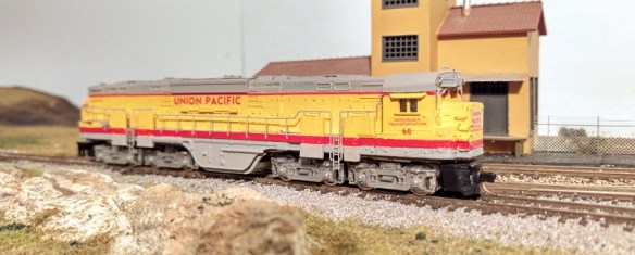
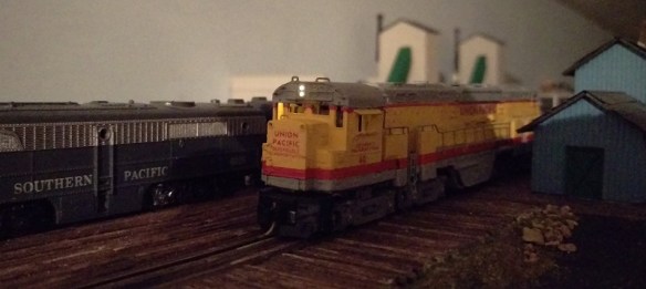
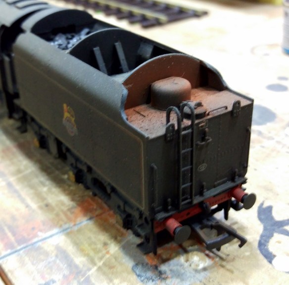
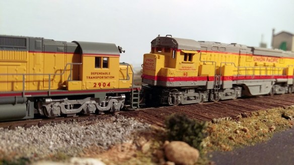
Later that evening C-855 no 60 received its handrails and ladders which made a dramatic change to the appearance of the loco.  All that’s left now is to finish painting the trucks and pilots and weather her up.
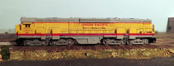
C-855 WIP 10

The C-855 is part of Alco’s ‘Century’ series of locomotives.  The C-855 is by far the largest and the only twin-engine locomotive. Two locomotives down the list is the C-630 and, as you can see, there’s a considerable difference.

C-855 WIP 11

Because the trucks are grouped in pairs linked by span bolsters they push the locomotive up, giving it towering dimensions compared to most other conventional two and three axle locomotives.

C-855 WIP 12

Once the C-855B unit arrives, which is due next week, it too will be painted by MRS and then all three will be weathered and ready for service.  These three are destined for a place in the UP engine sheds on the ‘Somewhere West‘ which you can find in the Layout Gallery or by clicking on the link.  I expect we’ll be getting lots of photos and videos of them in service and I also expect them to last a lot longer than the originals.