Drawing an Alco C-855 for N Scale Part 5

If you have been following my blog for a while you will know that I have been working on an N Scale Alco C-855.  You can read the first part here.  In this week”s post I will share with you what I have done to finish the A unit and get it ready to order a test print.

In my last post about the C-855 I showed you the first print of the metal chassis extenders and how I fitted them into the Con-Cor Turbine/U50 chassis.

C-855 Chassis Build 15

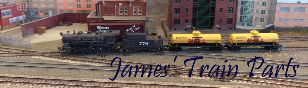
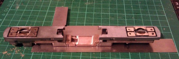
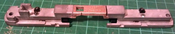
This chassis runs well, and pulls even more than in its original counterpart; probably due to the increased weight.  However there were a few issues with the print so I have improved the 3D model to rectify them.  In the image below you can see both parts from the top and bottom.

Alco C-855 Chassis Extenders mk2 (render)

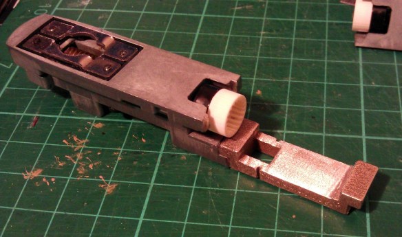
The space for the motor has been widened by a fraction as the motor was a tight fit in the first print.  The wire channel has also been increased in size so the motor wire is a better fit.  I have also made some changes to the bottom of the lower section.  The arrows point forward on both parts to help with orientation when assembling the chassis.  There is now a rectangular nub that sticks out to locate the fuel tank on the bottom of the locomotive.  Also a square hole has been added which has been designed to take a 3D printed screw fixing which is used to hold on the fuel tank.  The exploded view below shows how these fit together.

Alco C-855 Fuel Tank Fitting 1 (render)

I have designed this assembly so the original Con-Cor turbine/U50 screw can be used athough any similar size screw will work.

Alco C-855 Fuel Tank Fitting 2 (render)

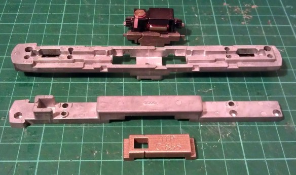
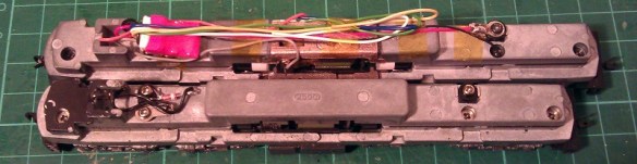
This section of the fuel tank is only the bottom as the sides are part of the main body.  Looking at the image above you can see a square hole in the side of the fuel tank, this is designed to receive a nub sticking out from the shell. You can see the nub in the image below which shows half of the shell.  As the bottom of the fuel tank is fixed with the screw it becomes a solid fixing for the shell.

Alco C-855 In Side Shell (Render)

As with a lot of ready-to-run locomotives, to remove the shell it can simply be spread in the middle and lifted off.

To make painting and adding decals to this model easier the four large sand boxes on the sides have been made as separate parts.  The rear six are the same but the front pair are longer as they have to step over parts of the chassis.  The shell has slotted fixings in the side of the running board to receive the sand boxes so they can be securely fitted.  The holes on the tops are handrail fixings.

Alco C-855 Sandboxes (render)

As with my DT6-6-2000 and RT-624 locomotives my C-855 will come with crew for the cab, Bert and Ernie.  The controls on the console are very basic but this is N scale so once they are inside the cab it will be hard to see anyway.

Alco C-855 Crew (Render)

Because of the shape of the chassis, there is a large chunk of metal sticking up into the cab, the crew had to be pushed to the sides.  There are locator pockets in the shell walls to receive the crew once they have been painted.  As the C-855s ran in an A-B-A configuration you may not want crew in the rear A unit so they can simply be left out.

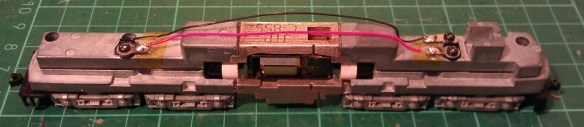
Below you can see the crew in their place with half the shell removed.

Alco C-855 Inside cab (Render)

This view also shows you the headlight fitting in the roof of the cab.  The shell has been shaped to receive a standard 3v 2mm LED.  A nice warm white LED can be fitted directly into the roof of the cab and a pair of headlights will shine from the front.  This area will need to be painted black on the inside to prevent the light from shining through the shell.

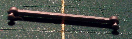
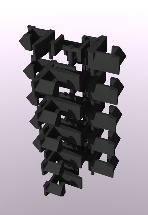
Even the horn is a separate 3D printed part; this is both to make it easer to paint and to protect it from being knocked off in shipping.  Below you can see all the 3D printed plastic parts for one C-855.  The large gears are the drive shaft extenders which are needed when the chassis is extended.

Alco C-855 3D printed parts (render)

In the cab you can see lots of holes; this is because all the grab irons and handrails plus many other details are brass parts that will be supplied in a brass Additions set. The set will also include some of the metal walkways, windscreen wipers, side ladders, MU hoses and sun visors for the cab.

So putting this all together, this is how the N Scale C-855 will look.  Please note the trucks under the 3D model are not yet correct.

The end will have brass grab irons up the center and walkways over the air intakes.

Alco C-855 end (render)

The cab with all of its brass parts will be well detailed

Alco C-855 666.Front (render)

Overall this monster of a locomotive has an imposing presence.

Alco C-855 (Render)

The next step is to finish the drawings for the B unit and design a dummy chassis so an A-B-A set can be made without powering all the units, if required.

The new 3D printed metal parts as well as the 3D printed plastic parts for the C-855 have new been sent for test printing so I should have the first N Scale C-855 within the next few weeks.  Once it arrives and I have cleaned up all the parts I will share some images with you.

Drawing an Alco C-855 for N Scale Part 4

This week I’ve been working on the Alco C-855 project and I’ve assembled the chassis using the 3D printed metal chassis extenders.  In this post I will share with you how I did it.

You can read about the design for the metal and plastic parts for the extenders in my earlier post which you can find here.  The metal chassis extenders are required because the donor chassis, taken from a Con-Cor model of a GE U50, is not long enough for the huge Alco C-855.  The chassis extenders, pictured below, have been 3D printed in stainless steel.

C-855 Chassis Extenders 1

To start with the donor chassis is stripped down so only the two main metal parts are left.  It is best to remove any moving parts when cutting the chassis as metal filings can get into the gears and bearings causing damage at a later date.

C-855 Chassis Build 1

The two parts pictured above, along with the new sections, are ready to be marked for cutting.  I like to use a permanent marker to shade in the areas that need to be cut, as you can see below.

C-855 Chassis Build 2

Once I was happy with the marked areas I used a hack saw to cut the unwanted chassis sections out.  I will be providing instructions when these parts are released for sale with dimensions for where to cut.  Once removed the chassis sections looked like this.

C-855 Chassis Build 3

To fit the parts together I used a superglue but an epoxy will work just as well.  Because the parts are designed to fit together along a step it is fairly easy to get them in the right place. However it is still possible to fit them together at a slight angle so I recommend using straight edges as guides.  I used the back of a metal ruler for a base plate and my metal square as a side.

C-855 Chassis Build 9

I started with the top section and, as this is a test piece, I only glued one side first.  In the photo below you can clearly see the difference in size between the new section and the part that was cut out.

C-855 Chassis Build 7

Before I glued the other side of the top section together I wanted to check things were going right so I test fitted in the lower section of the chassis with the motor. As you can see from the photo below there was a slight problem.

C-855 Chassis Build 5

The motor appeared to be sitting too high in the lower part which looked to be preventing the top section from coming down squarely.  However after further inspection the motor was found to be in the correct place but the top section was a bit too thick.  This was caused partly by the rough surface on the unpolished stainless steel, and also because the superglue added a layer of thickness between the parts.  This was easily resolved by grinding down the underside of the chassis extender.  I used a sanding stone in a Dremel-style tool and removed some of the thickness as you can see below.  Interestingly the stainless steel is much harder than the metal used for the original chassis and it took a bit if working The metal got incredibly hot but the superglue joint held up with no problems.

C-855 Chassis Build 8

With the extension part modified the motor section now fitted properly, so I glued the other end on using the same metal square and ruler.

C-855 Chassis Build 10

The gap you can see in the picture below at the top of the right hand joint is because I slightly over-cut the chassis. However that is not problem as the step below is the part which correctly positions the extension.  I later filled this gap with more superglue.  I used the Gel Control Superglue made by Loctite which is perfect for jobs like this as you get a bit of working time before it dries and, being a gel, it will not run.

C-855 Chassis Build 11

Before moving on I also did some squareness checks as you can see below..

C-855 Chassis Build 12
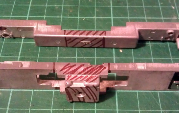
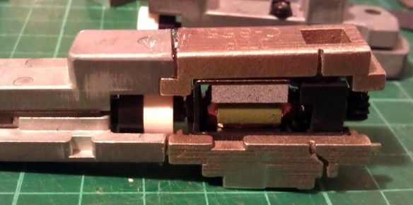
Now the top section was complete I could position and glue in the motor section.  You may have noticed I left the top and bottom sections of the chassis bolted together throughout most of this.  I did this to help ensure everything was in the correct place, particularly when it came to fitting the motor section.  As it happened I did cut the lower front chassis section a bit short and if I had glued the whole bottom section together tightly it would have been too short.  However as the chassis parts were bolted it all worked out well and below is the chassis glued together.

C-855 Chassis Build 13

Next I refitted the trucks and other internal parts ensuring there werre no metal fillings in any of the moving parts. I lubricated the motor, gears and drive shaft bearings and also put a strip of Kapton tape over the top motor brush connector.  It was ever-so-slightly touching the metal of the chassis extender and, as I proved in my prevision post, these stainless steel parts conduct electricity very well.  If this locomotive was going to be run as a DC locomotive this would be great but it will be DCC so I needed to isolate the motor.

Although the chassis extenders are great conductors the fact that I used superglue for the joints helped to form a perfect electrical barrier, so to ensure I get the benefit of all the power pickups, I bridged the chassis extenders using the original bolts, as you can see below.

C-855 Chassis Build 14

The two nearside bolts are in plastic sleeves so they don’t touch the top section of the chassis but conduct power from the bottom section.  The bottom section is connected to the right hand rail and the top is connected to the left.  To complete the test I also fitted a DCC decoder and the lighting and function wires are simply taped to the chassis for later use.

C-855 Chassis Build 15

The longer mechanism had no problem navigating some S bends and small radius turnouts on my switching layout.  I will also do a few tests on a bigger layout this week with a train in tow to see how it performs and I will share a video of that with you.

Below you can see some side by side comparisons between an original Con-Cor U50 chassis and my extended C-855 one.  The original chassis weighs 170g (5.99 ounces) and the extended one weighs 186g (6.56 ounces).  The C-855 did have 500 more horsepower than the U50 so this extra weight will help with traction.

C-855 Chassis Build 16 C-855 Chassis Build 17

I have now made some modifications to the chassis extension 3D model drawing to fix the issue I had with the first build. I will do one more test print before I make them available,, just to confirm that everything will fit together without modification.

The next step for the C-855 is to finish the 3D model for the shell and brass Additions.  Once I get them drawn up and ordered from the printer and etcher I will share them with you.

Replacement Eccentric Rods for a MRC/Rowa N Scale 2-8-4 Part 2

A few months ago I produced a 3D model for some replacement eccentric rods for a MRC/Rowa 2-8-4 Berkshire steam locomotive.  My Berkshire was missing one and although it ran well without it I wanted it to look right.  You can read the post here.  I have now had some of the eccentric rods printed and in this post I will share with you how they came out.

I printed the new eccentric rods in Shapeways’ Frosted Ultra Detail material; I did this just before they announced their new Frosted Extreme Detail material.  The new FXD would be ideal for these parts.  Anyway they arrived and once cleaned up looked very good as you can see in the image below.  The bottom one is an original from the other side.

Berkshire Eccentric Rod Repair 1

In the image below you can see the two C shaped fixings which the eccentric rod clips into.  One is on the 3rd driving wheel and the other is under the bell crank.

Rowa 2-8-4 Berk Acc Rod 2

The new rod clipped into the fixings fairly easily.  I found it worked best if you fit to the bell crank end first, then the 3rd driver.  As the pin on the 3D printed rod is very small there is the risk of breaking it off so I will be supplying them in a pack of four just in case.

Berkshire Eccentric Rod Repair 2

The new rods moved freely and showed no signs of binding.

Berkshire Eccentric Rod Repair 3

Next came a running test and the loco ran as good as ever but there was one tiny issue.  And when I say tiny I mean 0.34mm.  If you have a closer look at an original eccentric rod in the image below you can see the tiny pegs that clip into the C fixings.  They both appear to eccentric to the center of each end but in fact the left hand end is closer to the center, 0.34mm closer.

Berkshire Eccentric Rod Repair 4

Now for such a small dimension you wouldn’t think it would make such a big difference.  Have a look at the video below that shows the locomotive running with the original eccentric rod fitted and see how much the bell crank rocks back and forth, or gives the impression that’s what it’s doing.

Then look at this video showing the locomotive with the 3D printed rod fitted.

Although the rod runs well the slight extra length corrects the offset the eccentric rod is designed to make and the bell crank is hardly moving.  Also it creates the visual effect that the end of the eccentric rod is closer to the center of the 3rd wheel, which would cancel out the movement.  Although this is only a cosmetic problem I would like to get it right and, happily’ this is an easy thing to fix.  I’ve moved the peg into the correct place in the 3D model and when I get a reprint done it will hopefully be all sorted.  I think for the next set I’ll try these in the new FXD as well.  So for now the Berkshire is back on the shelf.

For next week’s post I have something a bit different to share with you; on the weekend I was invited to a running session at the McKinley Railway here in the UK which I greatly enjoyed as it is more than just a model railway.  Next week I will explain what it’s all about and share some photos and videos with you.

Short Replacment Rapido Couplers in the New BS&F

In last week’s post I released my designs for short replacement Rapido couplings to reduce the distance between coaches on N Gauge rolling stock.  You can find the post here.  Since my post Shapeways have announced their new pricing structure which will be rolled out on the 7th of October.  For the most part the changes are an improvement because several materials will be come cheaper to print in. However, due to a complication with the Short Rapido Couplings model, it will become impractical to print the model as it is.  In this post I will share with you what changes I am making to continue to supply these couplings.

The default material for these parts is Shapeways Black Strong & Flexible.  It is one if the cheaper materials, ideal for parts like this which have a lower level of detail but which still need to be functional.  The new pricing structure for BS&F will now charge a fee for each part in the model, consequently with a pack of 20 couplings this makes the model impractical.

To solve this I have added all the parts onto a sprue, as shown below in the rendering.  The sprue has been drawn to the minimum requirements so as not to waste material or increase cost, and to make it easier to remove the couplings from the sprue.

Short Rapido Replacments Tree Black

The couplings are also available in the Frosted Detail material which is not affected by the new pricing structure.  However, as the model needs to be updated to incorporate the sprue this means the FD price will also be slightly affected. Both kits for 20 and 40 couplings have now been updated ready for the change on the 7th and are still available on the Shapeways site.

My original intention for the couplings was to have a 3D printed product which was delivered ready to use.  And I can still offer that service by order these couplings in bulk myself and offering them for sale from this blog/website.

I can do this by ordering several hundred couplings at once; then it becomes practical to draw things in a different way as Shapeways software is very clever in how it calculates volumes and printability of models.  For example, if I draw two rings, as shown below, interlinked so they cannot be separated, just like a chain, the software will recognize that this is actually one part even though the rings do not touch each other.

3D Rings

By using this advantage I have drawn a cylinder full of holes.  Each hole is not quite large enough for one of my couplings to fall through so once the model is filled with couplings the Shapeways software will only charge for one part.

Rapido Replacments Cylinder

If you would like a pack of 20 or 40, or any other number, of Short Replacement Couplings that are ready to use on delivery I can supply then, please use the contact page or send me an email at Jamestrainparts@yahoo.co.uk.

So you can choose either to order the couplings attached to the sprue direct from Shapeways with their delivery schedule, or you can purchase direct from me which may have a slightly longer delivery time, unless I have that number in stock.

This change in Shapeways pricing policy also affects a few other models of mine but nothing that requires a change like this.

Next week I really do plan on getting back to the HO Scale Union Pacific water tender project and I hope to be able to share with you some photos of the painted car.

Drawing a HO Scale Union Pacific Water Tender Part 2

In my last post I shared with you the designs for my HO Scale Union Pacific auxiliary excursion train water tenders; you can find that post here.  Since then the test print has arrived and in this post I’ll show how it came out and the few improvements I have made.

As shown below the kits arrived from Shapeways with the Frosted Detail parts in a transparent form covered in the waxy residue left over from the print process.

HO Tender Kit Raw

I cleaned the parts using Goo Gone to break down the wax, however with this kit being HO it is considerably larger than my normal N Scale parts so a bigger container was needed.  An ice cream tub works very well for this as the lid can be sealed; the Goo Gone will evaporate if it is in an open container.  And I can strongly recommend honey flavour!

Goo Gone Ice Cream Tub

Only the parts printed in FD needed to put in the Goo Gone, the White Strong & Flexible material does not print in the same way and has no waxy residue.

After the cleaning process the FD parts turned opaque and the detail could now be seen as shown below.

HO Tender Kit

This is my first print in the FD material and it came out a little bit coarser than the Frosted Ultra Detail.  This particular model also had a lot more wax build up than I am used to which left a lot of powder on the model from the wax residue, and this needed scrubbing off with a toothbrush.  In the photos below you can still see a lot of the powder around the detail.

HO Tender Detail 1 HO Tender Detail 2 HO Tender Detail 3 HO Tender Detail 4 HO Tender Detail 5

Below you can see the trucks have powder in the holes, clogging the detail.

HO Tender Truck Detail 1

Most of it was easily removed using a toothpick and a toothbrush but there is still more to remove.HO Tender Truck Detail 2

The trucks have been designed to be used with Proto 2000 Wheels as shown below but the distance between the truck side frames is a little too tight so for the test print I have had to use plastic wheel sets from some old box cars.  This has now been corrected in the 3D model as well as the gap you can see between the air cylinder and the pipe.  I have ordered a test print of the new trucks for this model to check the Proto 2000 Wheels work.

HO Tender Wheelsets

As with the N Scale kit the ladders are tied together on a ring which also has the head lamps attached to it, as shown below.

HO Tender Ladder Detail 1 HO Tender Ladder Detail 2

The chassis, tool boxes, flag plates and truck bolsters were all printed in WS&F and all came out well.  The bolster pins are fixed together to help reduce the number of small parts and can easily be cut apart.  HO Tender WS&F Parts

The holes in the chassis for the pins needed to be very slightly drilled out to allow the pins to be a good fit.

HO Tender Chassis  Trucks
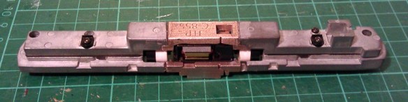
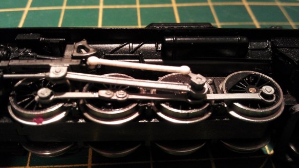
The detail on the tool boxes came out very well in the WS&F, it had the level of detail necessary for this part.
HO Tender WS&F Tool Boxes

The chassis fitted into the shell a little too tightly so I have also altered the shell in the 3D model at one end to make for a better fit.

HO Tender Under Side 1

The chassis only fits in one way as each end has a different shape which fits around the coupling connection mounts.

HO Tender Under Side 2 HO Tender Under Side 3
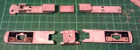
Each end of the shell has two pegs to mount a Kadee coupler; I have used No.5 couplers.

HO Tender Coupling 1 HO Tender Coupling 2

The tender still needs some more checking over before I am happy to release it and I also want to check that the new trucks work with the Proto 2000 wheel sets but I think it is just about there.

HO Tender Test Print 1 HO Tender Test Print 2

As I have already said in the previous post the cost of printing in the FUD material led me to test print in the FD material to make the model more wallet-friendly. Having assessed the overall finish of the FD test print the finish is a bit rougher than the FUD so when I do release the tenders for sale I will make them available in both materials to give you the choice.

In a later post I will show you what the FD HO tender looks like painted in the UP colors.

Discovering the Possibilities of Etched Brass

With two locomotive shells already available to buy and several more in the pipeline I have started to look at what can be done to develop them further.  The most frequent request I have had from customers has been for brass handrails so in this post I want to share with you how I’m working on that.

3D printing offers many advantages over other forms of modeling; one of them is the level of detail which can be achieved.  My current locomotive shells and parts have been designed to be printed with a detail level of 0.1mm which for parts such as small vents and door handles is perfect.  But when it comes to self-supporting items, such as handrails, they need to be thicker in order to survive the print and handling process.  Typically a wire part such as a handrail has to be at least 0.8mm in diameter.  Now I know that doesn’t sound a lot but in N scale at 1:160 that is equivalent to 128mm which is very big, and although it is passable, compared to injection molded or wire handrails on a lot of the new ready to run models, it is huge.

The 3D printed handrails on the EMD DD35 pictured below are clearly much larger than the injection molded ones on the Atlas C-628 model pictured underneath.

Locomotive Shells

Atlas C-628 1

The answer lies in brass etching.  Referred to as acid-etching, resist-etching and photo-etching, it’s a process of removing metal in varying layers around a design, leaving behind the composite parts of the model. The main advantage to this is we are dealing with metal which allows it to be incredibly thin and detailed.  The brass metal sheet which I will be working with is only 0.2mm thick and I can etch out parts that are only 0.24mm wide.  This is ideal because I can model handrails at actual scale size.  Although the parts are etched from a flat sheet, once the handrails are painted their ‘squareness’ will be smoothed out.  They can be also designed to be bent in the correct places to achieve the shapes we need.

To begin with I looked at the handrails for the Baldwin DT6-6-2000. There are four side rails and two end rails on this locomotive and I needed to find an efficient and cost-effective way to lay them out so they didn’t take up too much room on the sheet but still had enough metal around them for support.  At this point I realised there would be some spare space on each handrail set so I looked again at the DT6-6-2000 to see what else I could add.  Looking at the photos of the original locomotives working up and down the country I noticed a lot of them had sun shades over the cab windows.  So I have included a set of sun shades with each set of handrails.  Below is the rendered image.

Baldwin DT6-6-2000 Additions Render

I’ve also designed a set of handrails for my EMD DD35 model as pictured below and will be making this set available soon.  The set includes the two main side rails and the four corner rails, there are no sun shades with this locomotive as it has no cab!

EMD DD35 Additions Render

The corner rails also shown below will be etched flat and once removed from the sheet can be bent to form the correct shape.

DD35 Handrails Additions Close Up Render

As you can see from the images above the brass etched parts will form part of my new ‘Additions’ series, which will be available alongside my established range of Shapeways products soon. You’ll have the choice to buy the complete locomotive kit from Shapeways and then if you choose you can add further detail by using the Additions products which will be available direct from this site. I’m striving to make both options as affordable as possible, and at the same time giving you a working, detailed locomotive model to suit your budget and modeling choice.

If you’re interested in being the first to try these brass etched details drop me a message through the Contacts page, I look forward to seeing these in action!