Earlier this week I had a nice message, via email, asking if I’d received a question sent through my contact page, and sadly I hadn’t. After doing some testing it turned out that for some reason my contact page was no longer sending me messages.
This has now been fixed and messages are coming through but I don’t think it’s been working for a few months, so my apologies to anybody who has sent me a message and I didn’t respond. I think the problem started around June last year, again my apologies that I have only just realized and have missed your messages.
But as I say it’s now been fixed and you can send me messages again through the contact page. Alternatively, you can email me at jamestrainparts@yahoo.co.uk.
Again my apologies for any messages that have been missed.
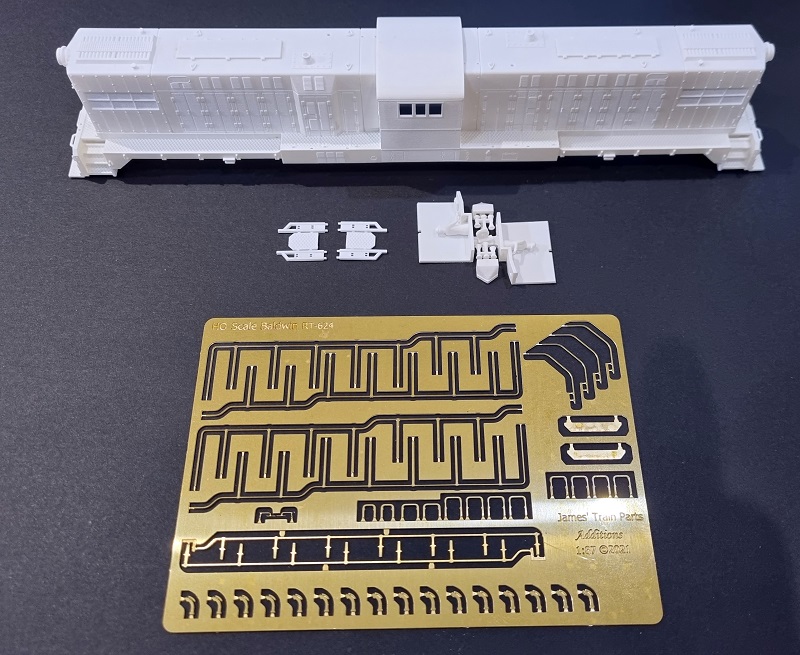
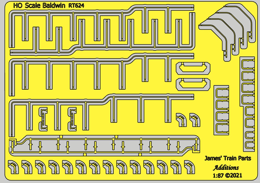
My 3D printed kit for a HO Baldwin RT-624 was released in August last year. The kit included the main body shell, 3D printed crew, and details, and also available was an etched brass fret with handrails, grab irons, and details to finish the shell.
The kit was designed to fit onto a Bower HO C-628 or C630 chassis, as shown below, and a 3D printed kit to rotate the trucks was also made available.
The basis for both of the kits was my previous release of my HO Baldwin DT6-6-2000 which, just like the prototype, was the RT-624’s predecessor. The chassis modification kit for both locomotives is the same, but the body kits are quite different once you start looking at the details.
When creating the 3D model for the RT-624, I used my model of the DT6-6-2000 as a starting point and modified it as required. But as is often the case with obscure locomotives which are no longer in existence, finding exact information can be tricky and some of it had to be assumed from photos and film.
However one of my fellow modelers, Gus Foster, has kindly been helping me to fine-tune the model and update some of the finer details for the PPR RT-624 models.
The first and possibly biggest update I’ve made is the difference between the DT6-6-2000 and RT-624 cab windows. The DT6-6-2000 has three window panes and they’re high up on the locomotive, as you can see below. (A Baldwin Locomotive Works builder’s photo https://www.american-rails.com/20001.html)
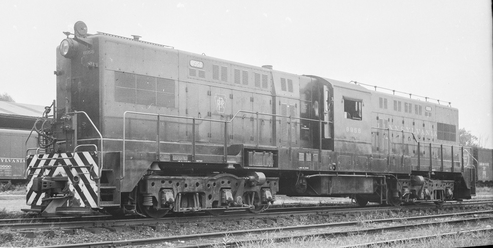
Whereas the PPR RT-624’s window is lower, narrower, and consists of a pair of panes. You can see this below with PPR 8956 at Zanesville, Ohio, July 23, 1954. (Photographer Paul B. Dunn).
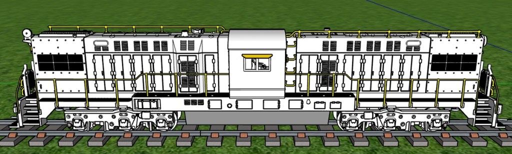
Why I hadn’t noticed that the window was lower was because that would make it very close to the cab floor, but as Gus pointed out, the floor on the RT-624 was lower. There’s a seam you can see running horizontally under the window; this is where the cab floor is fitted in. So in my 3D model, I’ve corrected the windows and lowered the seam marking the cab floor.
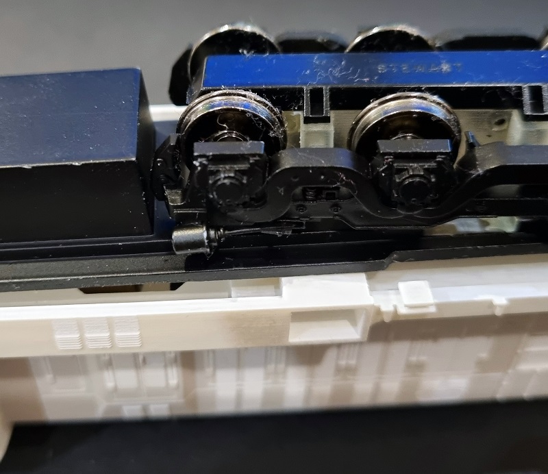
Also in the view above, I made several small changes. At the left of the image in the walkway, just before the step, is the cab signal box opening. For my original 3D model I’d scaled this from a photograph, but I’d made it a bit short. Gus was able to give me some more accurate dimensions. But, as you may have read in a previous post (A Baldwin RT-624 in HO – Part 5) the depth of the cab signal box opening had to be reduced to fit the chassis, you can see the first test print not fitting below.
With the cab signal box opening now increased but made shallower it didn’t look right. My solution was to fill the opening in just the same way as the original. Going back to the 3D model below you can see the opening is filled, just like the opening in the photo of PPR 8956 at Zanesville.
Gus also pointed out the fuel fill, which is the circular detail under the bottom left of the cab, which was originally too far to the left, the access hatches under the cab were a little too large and there should have been two more. As you can see above, these have also been updated. The last thing Gus helped point out was the tiny angles on the underside of the plate where it meets the walkway. In the image below this is just to the left and below the brass handrail stanchion. On the original model, this was horizontal.
However, when adding this little detail I spotted something else. A big difference between the DT6-6-2000 and the RT-624 is the walkway with the cab signal box opening, because it’s longer, creating one odd handrail and three which are the same. This I had already modeled. But what I’d assumed was that the handrail on this odd side would be the same just with the crank further along. But that’s not the case. The three regular handrails, just as the four on the DT6-6-2000, have eight stanchions. This is shown on the right in my 3D model below. But the odd one, on the left, above the cab signal box opening, only has seven and they are spaced out further.
Looking back at the photo of PPR 8956 you can see this.
Having changed that in the 3D model it gave me a dilemma because it changed the etched brass details. Not only will it require a new etched brass detail but the layout would no longer work, the previous layout relied on the handrails fitting together to save space, but with one set having an odd number of stanchions at different spaces that couldn’t happen. But after a few attempts at moving everything about I managed to make it work like this.
I also took the opportunity to slightly increase the thickness of the windscreen wipers and add a second pair as the original set was very delicate and prone to bending before they reached the model.
Thanks to Gus, the updated HO Baldwin RT-624s are now available to order. All the parts are available from the links below;
The next version of this locomotive will be the single Minneapolis Northfield & Southern locomotive numbered Twenty-Five which I’ll soon have finished.
For the first post of the New Year, I thought I’d start by releasing a new product that would also finish a project started last year.
The second generation of the Bachmann HO 4-8-4 locomotives, just like the first generation, has an issue with splitting axles so I’ve designed a set of 3D printed replacements. You can read the first post about this here and the second here.
The second generation 4-8-4 chassis is an improvement on the first and has a much thicker drive gear, which in turn means it has stronger teeth. This means the 3D printed gear axle can be a direct copy of the original, although I’ve made some very minor changes to the overall design.
The replacement axle set will contain three axles and one gear. As you can see below the axles all have square holes which makes quartering (setting up the valve gear and side rods) much easier, because each wheel can only fit at 90° rotations. One thing that’s important is to clean out this square hole as it will almost certainly have some 3D print residue inside. Although this is a waxy substance it still has a thickness and if the wheel is inserted before removing this, the fit will be too tight and the replacement axle may crack. I use a very small flat blade screwdriver, or needle file with a square point to run along the square hole corner and scrape out the residue.
If the original gears have split and no attempt has been made to fix this then the old parts can simply be pulled out, they may even fall out, and the new parts can be put in. But if an attempt to repair the original axles with glue has been made then this will need to be cleaned up. On the model below the rear two axles came right out but the front two have been glued. Using a pair of side cutters I cut or rather cracked the axle in half.
Some parts then fell away but some remained stuck, so I used some pliers to pull them out. When doing this be mindful of what you’re holding onto and how the force of pulling is restrained, as you don’t want to bend and mangle the side rods and valve gear.
With all the plastic removed the void in the wheel will probably still have glue in it as you can see below. This will also have to be removed. How you do this will depend on the type of glue used, but the wheel is made from metal with a hard plated surface so normally it can be scraped off. I tend to use a mixture of a small flat screwdriver, craft knife and tweezers. I tend not to use files or anything abrasive that can damage the wheel.
To see if all the glue has been removed one trick I discovered is to use one of the old axles, if you still have one intact that is, to test and see if it fits. It doesn’t matter if the old axle is cracking, as long as you can fit it into the wheel. Below you can see the axle fitted onto a wheel that wasn’t glued. There’s a small gap between the wheel and the step on the axle which is correct.
Fitting the old cracked axle into the wheel with the glue, you can see it won’t go in as far, because there’s still some glue in the base of the wheel void. So this’ll need to be removed.
Once all the glue is removed the wheel void should look something like this. All the metal surfaces I scraped with the tools are now shiny, any glue even if transparent would show up as a dull area.
With all the wheel voids cleaned up and a test fit done with an old axle, the new axles and gear can be fitted.
With the wheels pushed all the way in, this should leave that small gap between the wheel and step on the axle; the wheels should be at the right spacing. But it’s always a good idea to check this with a wheel gauge. For HO and OO gauges 14.4mm (0.5669″) is the correct spacing from the back of each wheel, commonly known as the ‘back-to-back’. If the gauge is too tight a wheel can be pulled out ever-so-slightly. Be careful not to twist the wheel when doing this as you can crack the axle. If the gauge is loose then one of the wheels need to be pushed in further.
And that’s it, the base plate can be refitted and the locomotive is ready to go.
My replacement axle and gear kit for the Bachmann HO 4-8-4 Second Generation is available here.
Next week I intend to share an update for the HO Baldwin RT-624 project with you.
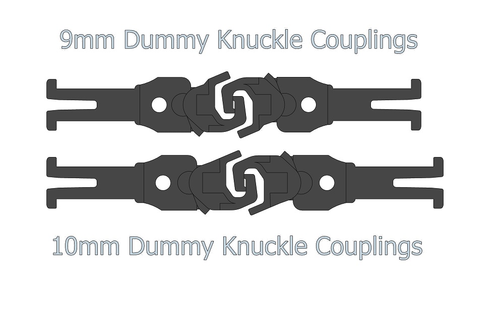
Back in September of 2019 I released my OO gauge dummy knuckle couplings which are designed to fit into NEM pockets on locomotives and wagons; you can read the post here.
These have the advantage of connecting directly to Kadee couplings without the risk of disconnecting. They are also 2mm taller than the normal Kadee couplings to allow for the different manufactures’ NEM pocket heights.
However, the need for a slightly shorter version has been highlighted so I’ve now made that available too.
Using two of my original couplings, the distance between the face of the NEM pockets is 20mm. The shorter version gives 18mm. The two millimeters doesn’t sound a lot, but in a rake of wagons it can make a big difference.
I have renamed the original releases slightly to differentiate them from the new ones. The ‘large’ refers to the knuckle height, not the length.
With the holiday season well underway Shapeways have announced their Cyber Monday sale. They’re offering 10% off everything from 12:01am EST all day on November 29th, 2021 through to December 1st, 2021 at 3:00am EST.
To enjoy the savings all you need to do is enter the code CYBER2021 at the checkout.
All of my 3D printed models, including the new HO RT624, are in the sale and can be found either by using the dropdown Shop menu above or going direct to my Shapeways site using the link below.
As promised in my last post I’ve now received the first test print for my new 3D printed axles for this locomotive, and in this post I’ll share with you how well they worked out.
This was the first test print for this design and although the design has been well thought out there’s always a chance that something’s not right, so I printed three sets.
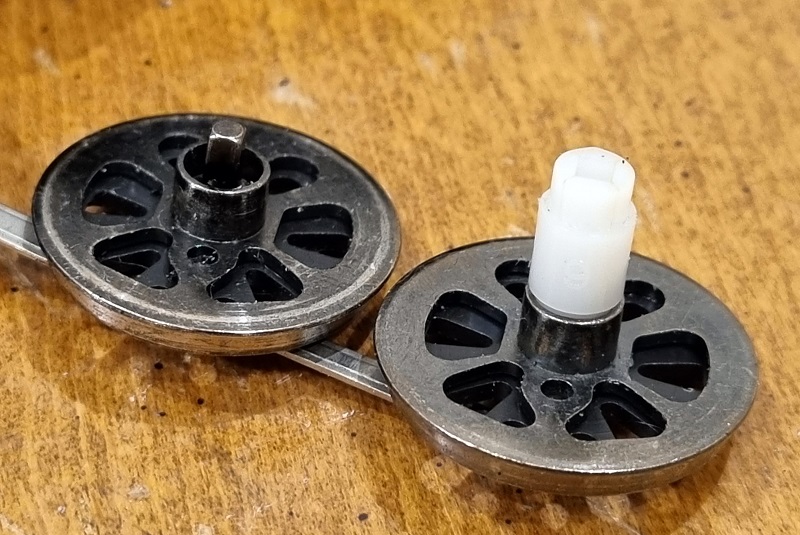
Each set contains one drive gear and three axles; below you can see an original axle and gear for comparison.
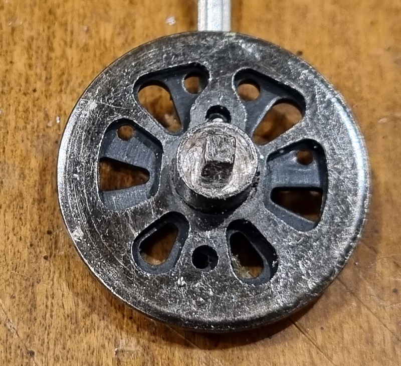
With the new parts removed from the sprue, a closer comparison can be made. And for me, the first thing that stands out is the size of the square hole. It appears much smaller on the new part than the original, which in fact it is, but by design.
The reason for the smaller size is based on the actual axle size on the wheels. I need the replacement parts to be a tight fit but not so tight that the new parts split. Sadly they do. The reason for this is due to variances in the wheel axles. The wheels are not machined, they are cast. Then they’re plated which gives them their shiny finish and conductive coating. However, this leads to a large variance in the thickness of the axles. It’s not enough to be really visible, but it’s enough to make a difference in splitting an axle or not. So I’ill need to adjust my 3D model to allow for this.
In order to complete this test, I still wanted to see if all the other aspects of the gear and axles worked, so I filed the square hole with a square needle file to enlarge them slightly.
Now the main drive gear is fitted. Quartering the wheels, or making sure the wheels are at 90° to each other, was very easy with the square holes, and the two wheels pushed into the axle without splitting it. Although the axles have been designed to correctly space the wheels it’s good to check the distance between the back of the wheels, which should be 14.4mm for HO. I use a laser-cut ‘back-to-back’ checker as you can see below. This should be a snug fit between the wheels.
All the axles have now been fitted and spaced. At this point, I check to make sure all the wheel assemblies can move freely and none of the valve gear is misaligned.
The last part is refitting the base plate to hold everything in. For this locomotive, the base plate also holds the pilot and trailing truck and clips onto the chassis. There are two screws in the base to hold it on.
And then comes the test, does it work under power? At this stage, I’m looking for three things; does it run freely, does it run at slow speeds without binding, and most importantly, how does it perform under load? If you followed my previous design post about the first generation of this locomotive, the original gear was very thin and the first design for the replacement gear cracked or stripped its teeth under load. Luckily the second generation already has a much thicker gear. In the short video below you can see I tested all of these.
And I’m pleased to say it passed all three tests. Given that I had to enlarge the square hole in all the parts I’ve now updated my 3D model to reflect this and I’ve ordered a second test print. I also made a slight change to the angle of the teeth on the main gear. I don’t see a problem but it brings the angle more in line with the teeth on the contacting gear.
Hopefully, the new test sets will be here soon and I’ll replace the gears in this chassis to see how well they fit. If everything is okay, with no splitting, I’ll release the Bachmann HO 4-8-4 Gen 2 replacement axles and gears for sale.


You must be logged in to post a comment.